EP0201980B1 - Appareil à enlever la viande des os, tels que des cuisses de volailles - Google Patents
Appareil à enlever la viande des os, tels que des cuisses de volailles Download PDFInfo
- Publication number
- EP0201980B1 EP0201980B1 EP86200823A EP86200823A EP0201980B1 EP 0201980 B1 EP0201980 B1 EP 0201980B1 EP 86200823 A EP86200823 A EP 86200823A EP 86200823 A EP86200823 A EP 86200823A EP 0201980 B1 EP0201980 B1 EP 0201980B1
- Authority
- EP
- European Patent Office
- Prior art keywords
- blades
- clamps
- curve
- disk
- bone
- Prior art date
- Legal status (The legal status is an assumption and is not a legal conclusion. Google has not performed a legal analysis and makes no representation as to the accuracy of the status listed.)
- Expired
Links
- 210000000988 bone and bone Anatomy 0.000 title claims abstract description 36
- 210000000689 upper leg Anatomy 0.000 title claims abstract description 10
- 241000287828 Gallus gallus Species 0.000 title claims abstract description 4
- 241001465754 Metazoa Species 0.000 title claims abstract description 4
- 235000013330 chicken meat Nutrition 0.000 title abstract 2
- 235000013372 meat Nutrition 0.000 claims description 15
- 210000003205 muscle Anatomy 0.000 claims description 15
- 230000008878 coupling Effects 0.000 claims description 14
- 238000010168 coupling process Methods 0.000 claims description 14
- 238000005859 coupling reaction Methods 0.000 claims description 14
- 230000005540 biological transmission Effects 0.000 claims description 8
- 230000009977 dual effect Effects 0.000 claims description 7
- 230000033001 locomotion Effects 0.000 claims description 7
- 239000000969 carrier Substances 0.000 description 8
- 210000003414 extremity Anatomy 0.000 description 3
- 210000002414 leg Anatomy 0.000 description 3
- 238000010586 diagram Methods 0.000 description 2
- 230000000694 effects Effects 0.000 description 2
- 230000007246 mechanism Effects 0.000 description 2
- 210000004417 patella Anatomy 0.000 description 2
- 230000001681 protective effect Effects 0.000 description 2
- 230000007480 spreading Effects 0.000 description 2
- 230000008901 benefit Effects 0.000 description 1
- 238000010276 construction Methods 0.000 description 1
- 238000007599 discharging Methods 0.000 description 1
- 239000012528 membrane Substances 0.000 description 1
- 238000000034 method Methods 0.000 description 1
- 229920000136 polysorbate Polymers 0.000 description 1
- 244000144977 poultry Species 0.000 description 1
- 230000000284 resting effect Effects 0.000 description 1
- 239000000725 suspension Substances 0.000 description 1
- 230000008719 thickening Effects 0.000 description 1
Images


Classifications
-
- A—HUMAN NECESSITIES
- A22—BUTCHERING; MEAT TREATMENT; PROCESSING POULTRY OR FISH
- A22C—PROCESSING MEAT, POULTRY, OR FISH
- A22C21/00—Processing poultry
- A22C21/0069—Deboning poultry or parts of poultry
- A22C21/0076—Deboning poultry legs and drumsticks
-
- A—HUMAN NECESSITIES
- A22—BUTCHERING; MEAT TREATMENT; PROCESSING POULTRY OR FISH
- A22C—PROCESSING MEAT, POULTRY, OR FISH
- A22C17/00—Other devices for processing meat or bones
- A22C17/04—Bone cleaning devices
Definitions
- THE INVENTION RELATES TO AN APPARATUS FOR BONING ANIMAL BONES HAVING A JOINT AT LEAST AT ONE END, SUCH AS THIGHS OF SLAUGHTERED CHICKENS, SUBSTANTIALLY COMPRISING TWO BLADES RECTILINEARLY MOVABLE TOWARDS AND AWAY FROM EACH OTHER WHICH CAN ENCIRCLE THE BONE AND A JOINT IN ORDER TO INCISE THE MEAT, TWO CLAMPS MOVABLE TOWARDS AND AWAY FROM EACH OTHER WHICH MOREOVER ARE MUTUALLY RECTILINEARLY MOVABLE TO AND FRO IN A PLANE PERPENDICULAR TO THE BLADES IN ORDER TO CLAMP A BONE END AND PULL IT THROUGH THE BLADES, AND DRIVING MEANS FOR THE BLADES AND CLAMPS.
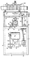
- THE APPARATUS SHOWN IN FIGURES 1 AND 2 COMPRISES A BOX 3 OF LONGITUDINAL BEAMS 4, 5 AND TRANSVERSE BEAMS 6-8 BEING SUPPORTED BY LEGS 1 AND STRUTS 2.
- THE BOX HOUSES A CURVE DISK 9 FOR RECIPROCATING A CARRYING BAR 10 OF THE CLAMPS 11 AND 12.
- THESE HAVE BEEN INDICATED BY DRAWN LINES IN THEIR MOST WITHDRAWN POSITION AND BY DOTTED LINES IN THEIR POSITION CLOSEST BEHIND THE BLADES 19 AND 20 (FIG. 6-8) WHICH HAVE BEEN MOUNTED ON A FRONT PLATE 13 OF THE APPARATUS.
- a PUSHER 26 IS MOUNTED WHICH CAN PUSH A BONE FROM A PAN 23 BROUGHT INTO CORRECT POSITION BY THE PAN CONVEYOR INTO THE OPENED CLAMPS 11 AND 12.
- THE CURVE GROOVE 27 COOPERATES WITH A CURVE ROLL 30 (FIG. 1) PROTRUDING UPWARDS FROM THE CARRYING BAR 10 RECIPROCATABLE IN THE BOX 3 THROUGH PAIRS OF ROLLS 31. AT THE FREE END OF THE CARRYING BAR 10 A CLAMP MEANS 32 IS MOUNTED, AND THUS THE CURVE DISK 9 SERVES TO RECIPROCATE THE CLAMPS 11 AND 12.
- THE OUTGOING SHAFT 55 (FIG. 2) OF THE MOTOR 15 BEARS A SMALL PULLEY 56. THE SHAFT 29 BEARING AT ITS BOTTOM END CURVE DISK 9,. IS PART OF A WORM WHEEL BOX 57 WITH AN INGOING SHAFT 58 BEARING A LARGER PULLEY 59. A STRING 60 IS PLACED ABOUT THE PULLEYS 56 AND 59.
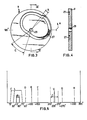
- THE BLADES 19 AND 20 HAVE FACING CUTTING EDGES WITH AN APPEARANCE BEING ADJUSTED IN THE USUAL MANNER TO THAT OF THE BONES TO BE PROCESSED, AND THEY ARE RELEASABLY CONNECTED TO BLADE CARRIERS 66, 67 BEING ABLE TO MOVE RECTILINEARLY TOWARDS AND AWAY FROM EACH OTHER BETWEEN PAIRS OF UPPER AND LOWER GUIDING ROLLS 68 PROTRUDING FROM THE FRONT PLATE 13.
- THE BLADE CARRIERS 66, 67 ARE LOADED TOWARDS EACH OTHER BY A TENSION SPRING (NOT SHOWN).
- CATCHING ROLLS 69 PROTRUDE FROM THE BLADE CARRIERS 66, 67, SAID ROLLS BEING ABLE TO COOPERATE WITH SPREAD ARMS 70, 71.
- THE LONGER SPREAD ARM 70 BEARS AT ITS TOP END A SPREADING ROLL 72 THAT CAN COOPERATE WITH THE CURVE DISK 18, (FIG. 2) AND IS ABOUT MIDLENGTH ROTATABLY SUPPORTED IN A BEARING 73 MOUNTED TO THE FRONT PLATE 13.
- BOTH SPREAD ARMS 70 AND 71 ARE CONNECTED TO A COUPLE BAR 75 IN SUCH A WAY THAT IF THE SECTOR DISK 18 TOUCHES UPON THE ROLL 72, BOTH BLADES 19 AND 20 SUBSTANTIALLY COVER THE SAME TRACK IN THE DIRECTION OF OPENING.
- a CAM 76 (FIG. 6) IS ALSO MOUNTED WHICH SLIGHTLY OPENS TO LET THROUGH THE REAR JOINT OF THE BONE (SECTION E OF FIG 5).
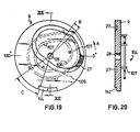
- FIG. 12 SHOWS THE PRINCIPLE OF COUPLING 16.
- ON THE CONTINUOUSLY ROTATING SHAFT 17 FOR DRIVING THE SECTOR DISK 18 IS A CURVE WHEEL 79 ON THE INTERMITTINGLY ROTATING SHAFT 80 CONNECTED THROUGH A CHAIN TRANSMISSION 81 (FIG. 1) TO THE DIFFERENTIAL TRANSMISSION 21 FOR DRIVING THE PAN CONVEYOR 22, IS A WHEEL DISK 82.
- FIG. 16 SHOWS AN APPARATUS IN OPERATION. I.E. THAT ALMOLST ALL THE MOVING PARTS WITH THE EXCEPTION OF THE LOADING PLACE OF THE PAN CONVEYOR 22 ARE OBSCURED FROM OBSERVATION BY LIDS AND COVERS. THE CURVE OF THE PAN CONVEYOR IS SCREENED OFF BY A CURVE SCREEN 101 FOR SECURITY S SAKE.
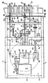
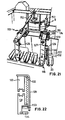
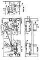
- THE APPARATUS SHOWN IN FIGS 17 AND 18 COMPRISES A BOX 3 OF LONGITUDINAL BEAMS 4, 5 AND TRANSVERSE BEAMS 6-8, BEING SUPPORTED BY LEGS 1 AND STRUTS 2 IN WHICH THE TRANSVERSE BEAM CONTRARY TO FIG. 2 IS INTERRUPTED FOR LETTING A BAR STRUCTURE STILL TO BE DISCUSSED, PASS.
- THE BOX HOUSES A CURVE DISK 9 FOR RECIPROCATING A CARRYING BAR 10 OF THE CLAMPS 11 AND 12.
- THESE HAVE BEEN INDICATED BY DRAWN LINES IN THEIR MOST WITHDRAWN POSITION AND BY DOTTED LINES IN THEIR POSITION CLOSEST BEHING THE BLADES 19 AND 20 (FIG. 24 AND 25) WHICH HAVE BEEN MOUNTED ON A FRONT PLATE 13 OF THE APPARATUS.
- HAS PANS 23 HAVING THROUGH-SHAPED CROSS-SECTIONS, THE DIMENSIONS OF WHICH ARE ADJUSTED TO THE BONES TO BE PROCESSED.
- THE CURVE GROOVE 27 COOPERATES WITH A CURVE ROLL 30 (FIG. 17) PROTRUDING UPWARDS FROM THE CARRYING BAR 10 RECIPROCATABLE IN THE BOX 3 THROUGH PAIRS OF ROLLS 31.
- a CLAMP MEANS 32 IS MOUNTED, AND THUS THE CURVE DISK 9 SERVES TO RECIPROCATE THE CLAMPS 11 AND 12.
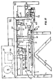
- THE BAR 110 CARRYING THE CURVE ROLL 108 IS CONNECTED TO THE BOX 3 VIA A RACKETT 111 AND THE HORIZONTAL BAR 112 RECIPROCATES THE LOADING ARM 26 WHICH IS SUPPORTED IN A GUIDE 113 (FIG.18) ON THE FRONT PLATE 13. ON THE BASIS OF FIG. 21, THE LOADING ARM SUSPENSION WILL BE EXPLAINED IN MORE DETAIL.
- THE OUTGOING SHAFT 55 (FIG. 18) OF THE MOTOR 15 BEARS A SMALL PULLEY 56.
- a STRING 60 IS PLACED ABOUT THE PULLEYS 56 AND 59.
- THE LONGER SPREAD ARM 70 BEARS AT ITS TOP END A SPREADING ROLL 72 THAT CAN COOPERATE WITH THE CURVE DISK 18, (FIG. 18) AND IS ABOUT MIDLENGHT ROTATABLY SUPPORTED IN A BEARING 73 MOUNTED TO THE FRONT PLATE 13.
- BOTH SPREAD ARMS 70 AND 71 ARE CONNECTED TO A COUPLE BAR 75 IN SUCH A WAY THAT IF THE SECTOR DISK 18 TOUCHES UPON THE ROLL 72, BOTH BLADES 19 AND 20 SUBSTANTIALLY COVER THE SAME DISTANCE IN THE DIRECTION OF OPENING. IF THE SECTOR DISK 18 IS DISENGAGED FROM THE SPREAD ROLL 72, THE TENSION SPRING 115 CAUSES THE BLADES TO CLOSE AGAIN. SUCH A MECHANISM CAN BE CALLED A PANTOGRAPHMECHANISM.
- a CAM 76 (FIG.24) IS ALSO MOUNTED WHICH SLIGHTLY OPENS THE BLADES TO LET THROUGH THE REAR JOINT OF THE BONE (SEE SECTION E OF FIG. 5).
- AN IMPORTANT DIFFERENCE BETWEEN THE TWO DESCRIBED EMBODIMENTS IS FOUND IN ADDING A SO-CALLED MUSCLE STRIPPER 116 AND THIS WILL BE ELUCIDATED ON THE BASIS OF FIGS 18 AND 21-23.
- THE FUNCTION OF THE MUSCLE STRIPPER IS TO PREVENT THE BLADES 19, 20 FROM CUTTING INTO THE MEAT, WHICH WOULD DECREASE THE EFFICIENCY OF THE APPARATUS WITH RESPECT TO THE QUOTIENT OF THE WEIGHTS OF THE REMOVED TO REMOVABLE MEAT.
- THE MUSCLE STRIPPER 116 COMPRISES IN FIG. 18 A STRIPPING ARM 117 HAVING SIMILARITIES WITH THE LOADING ARM 26 AND WHICH THROUGH A BAR STRUCTURE 118 IS DRIVEN BY A CRANK 120 ITSELF BEING MADE TO ROTATE BY A CHAIN 121 WHICH IS DRIVEN BY A CHAIN WHEEL BEING PLACED ON THE CENTRAL SHAFT 29.
- FIG. 21 SHOWS ALSO THAT THE ARMS 26 AND 117 EACH HAVE A PLATE 127 ROTATABLE ABOUT A HORIZONTAL SHAFT 126.
- THE CORRECT POSITION OF THE PLATES 127 IS ADJUSTABLE BY AN ADJUSTABLE STOP 128 BEING CONNECTED TO THE SLIDE, AND THE PLATES ARE LOADED BY SPRINGS (NOT VISIBLE) ACCORDING TO THE ADJUSTED POSITON.
- THE UPPER BLADE 122 WHICH IS HARD TO SEE IN FIG. 21 IS CONNECTED TO A BOW 129 BETTER VISIBLE THERE.
- THE UPPER BLADE 122 IS GUIDED ON THE FRONT PLATE 13 BETWEEN TWO WELDED-ON ANGULAR STRIPS 130 (ONLY ONE OF WHICH IS VISIBLE IN FIG. 21) AND THIS ALSO HOLDS GOOD FOR A VERTICAL LOWER BLADE 131.
- BOTH VERTICAL BLADES 122 AND 131 ARE PULLED TOGETHER BY A SPRING 132 SO AS TO DETERMINE THE CLOSED POSITION OF THE BLADES.
- a HORIZONTAL SUPPORT PLATE 138 (FIG. 18) IS MOUNTED IN THAT SECTION. FOR THE HORIZONTAL BLADES 19, 20 THEMSELVES THE DISTANCE BETWEEN THE PANS 23 AND THE BLADES 19, 20 IS COVERED BY A FOLDABLE SUPPORT PLATE 139 (FIG. 17)WHICH THROUGH A BAR STRUCTURE 140 IS DRIVEN BY A STOP 141 ON THE GUIDE PLATE 44 (FIG. 18). THE FOLDABLE SUPPORT PLATE 139 RETURNS TO ITS SUSPENDED POSITION UNDER THE INFLUENCE OF A SPRING 142 (FIG. 17).
- THE BLADE CARRIERS 66, 67 ARE PROVIDED WITH SUPPORTS 143 (FIG. 25) ON WHICH ADJUSTABLE STOPS 144 ARE MOUNTED. WHEN CLOSING THE BLADES 19 AND 20 THE STOPS ENGAGE DAMPERS 145 WHICH ARE MOUNTED ON THE LEVERS 146 (FIG. 26) WHICH CAN ROTATE ABOUT A SHAFT 147 CONNECTED TO THE BOX 3. ONE OF THE LEVERS 146 IS FIXEDLY CONNECTED TO A ROLL 148 RUNNING IN A CURVE WHEEL 149 BEING MOUNTED ON THE SHAFT 17 ON WHICH THE SECTOR DISK 18 IS ALSO MOUNTED.
- THUS AN ENTIRELY MECHANICALLY OPERATING APPARATUS IS OBTAINED, WHICH, IF DESIGNED FOR BONING THIGHS OF POULTRY, CAN HAVE A CAPACITY OF ABOUT 1250 BONES PER HOUR. REMOVING THE THIGHS CAN TAKE PLACE ON A CONVEYOR BELT (NOT SHOWN).
Landscapes
- Life Sciences & Earth Sciences (AREA)
- Engineering & Computer Science (AREA)
- Wood Science & Technology (AREA)
- Zoology (AREA)
- Food Science & Technology (AREA)
- Processing Of Meat And Fish (AREA)
- Meat, Egg Or Seafood Products (AREA)
Claims (18)
Priority Applications (1)
| Application Number | Priority Date | Filing Date | Title |
|---|---|---|---|
| AT86200823T ATE47282T1 (de) | 1985-05-13 | 1986-05-13 | Vorrichtung zum entfernen von fleisch von knochen, wie gefluegelschenkeln. |
Applications Claiming Priority (2)
| Application Number | Priority Date | Filing Date | Title |
|---|---|---|---|
| NL8501363A NL8501363A (nl) | 1985-05-13 | 1985-05-13 | Inrichting voor het ontbenen van dierbotten, zoals dijen van geslachte kippen. |
| NL8501363 | 1985-05-13 |
Publications (2)
| Publication Number | Publication Date |
|---|---|
| EP0201980A1 EP0201980A1 (fr) | 1986-11-20 |
| EP0201980B1 true EP0201980B1 (fr) | 1989-10-18 |
Family
ID=19845977
Family Applications (1)
| Application Number | Title | Priority Date | Filing Date |
|---|---|---|---|
| EP86200823A Expired EP0201980B1 (fr) | 1985-05-13 | 1986-05-13 | Appareil à enlever la viande des os, tels que des cuisses de volailles |
Country Status (5)
| Country | Link |
|---|---|
| US (1) | US4736492A (fr) |
| EP (1) | EP0201980B1 (fr) |
| AT (1) | ATE47282T1 (fr) |
| DE (1) | DE3666327D1 (fr) |
| NL (1) | NL8501363A (fr) |
Families Citing this family (38)
| Publication number | Priority date | Publication date | Assignee | Title |
|---|---|---|---|---|
| NO870070L (no) * | 1987-01-07 | 1988-07-08 | Norsk Naeringsmiddelforskning | Fremgangsmaate og anordning for filetering av kjoett. |
| AU592686B2 (en) * | 1986-12-05 | 1990-01-18 | David Geoffrey Bowen | Poultry deboner |
| CA1289310C (fr) * | 1986-12-05 | 1991-09-24 | David G. Bowen | Desosseuse de volailles |
| NL8700213A (nl) * | 1987-01-28 | 1988-08-16 | Meyn Maschf | Inrichting voor het scheiden van het bot en het vlees van de poten van gevogelte of een gedeelte daarvan. |
| DE3703836C2 (de) * | 1987-02-07 | 1995-12-21 | Heinrich Lindert | Bearbeitungsanlage für Geflügelfleisch |
| US4893378A (en) * | 1988-10-31 | 1990-01-16 | Systemate Holland B.V. | Revoving poultry thigh deboner |
| US5064403A (en) * | 1990-07-05 | 1991-11-12 | Sterling Manufacturing Company, Inc. | Apparatus for separating meat from poultry bones |
| US5176562A (en) * | 1991-04-26 | 1993-01-05 | Foodcraft Holdings, Inc. | Dark meat deboner with leg scraper |
| US5102369A (en) * | 1991-04-26 | 1992-04-07 | Foodcraft Holdings, Inc. | Dark meat deboner |
| US5173076A (en) * | 1992-01-22 | 1992-12-22 | Hazenbroek Jacobus E | Thigh deboner with tray conveyor |
| DE69708940T2 (de) * | 1996-01-23 | 2002-07-18 | Systemate Holland B.V., Numansdorp | Vorrichtung zum Entfernen von Fleisch von Geflügelschenkeln |
| US5976004A (en) * | 1996-01-23 | 1999-11-02 | Systemate Holland, B.V. | Partially deboned poultry product and process |
| US6007417A (en) * | 1996-01-23 | 1999-12-28 | Dapec, Inc. | Expandable poultry deboner with improved stripper disk |
| US6024636A (en) * | 1996-01-23 | 2000-02-15 | Systemate Holland B.V. | Expandable poultry deboner having a pre-cut installation |
| NL1005032C2 (nl) * | 1997-01-17 | 1998-08-03 | Systemate Bv | Voorsnijder voor het fileren van poot- of vleugeldelen van gevogelte. |
| US5865672A (en) * | 1998-01-15 | 1999-02-02 | Systemate Holland, B.V. | Deboning device and deboning apparatus for partially deboning meat |
| US7261629B2 (en) * | 2004-01-28 | 2007-08-28 | Systemate Group, B.V. | Poultry wing separator and partial deboner |
| US7464700B2 (en) * | 2006-03-03 | 2008-12-16 | Proliance International Inc. | Method for cooling an internal combustion engine having exhaust gas recirculation and charge air cooling |
| US8632380B2 (en) * | 2010-01-26 | 2014-01-21 | Foodmate B.V. | Method and apparatus for removing a sleeve of meat from an animal part having bone with knuckles on each of its opposite ends |
| US8157625B2 (en) * | 2010-01-26 | 2012-04-17 | Foodmate Bv | Method and apparatus for collecting meat from an animal part |
| US8789684B2 (en) | 2010-04-19 | 2014-07-29 | Foodmate Bv | Rotatable article support for a conveyor |
| NL2004573C2 (en) | 2010-04-19 | 2011-10-20 | Foodmate B V | Turning block alignment. |
| US8757354B2 (en) | 2010-04-19 | 2014-06-24 | Foodmate Bv | Turning block alignment |
| NL2006075C2 (en) | 2011-01-26 | 2012-07-30 | Foodmate B V | Rotationally indexed article support for a conveyor system having an alignment station. |
| NL2004574C2 (en) | 2010-04-19 | 2011-10-20 | Foodmate B V | Rotatable article support for a conveyor. |
| US8727839B2 (en) | 2011-01-21 | 2014-05-20 | Foodmate Bv | Poultry wing cutter for narrow pitch poultry lines |
| EP2667728B1 (fr) | 2011-01-26 | 2015-07-29 | Foodmate B.V. | Procédé de désossage de cuisses d'animaux pour en séparer et en recueillir la viande et appareil pour mettre en oeuvre le procédé |
| US8267241B2 (en) | 2011-01-26 | 2012-09-18 | Foodmate Bv | Rotationally indexed article support for a conveyor system having an alignment station |
| US8882571B2 (en) | 2011-01-26 | 2014-11-11 | Foodmate Bv | Method of deboning animal thighs for separating and collecting meat therefrom and apparatus for performing the method |
| US8430728B2 (en) | 2011-02-14 | 2013-04-30 | Foodmate Bv | Special cut poultry wing cutter |
| NL2009033C2 (en) | 2012-06-19 | 2013-12-23 | Foodmate B V | Weighing method and apparatus. |
| US8808068B2 (en) | 2012-10-29 | 2014-08-19 | Foodmate Bv | Method of and system for automatically removing meat from an animal extremity |
| NL2009718C2 (en) | 2012-10-29 | 2014-05-01 | Foodmate B V | Method of mechanically removing skin from animal parts. |
| US9078453B2 (en) | 2013-11-01 | 2015-07-14 | Foodmate B.V. | Method and system for automatically deboning poultry breast caps containing meat and a skeletal structure to obtain breast fillets therefrom |
| US8961274B1 (en) | 2013-12-18 | 2015-02-24 | Foodmate Bv | Selective tendon cutter and method |
| CN113412924A (zh) * | 2021-06-09 | 2021-09-21 | 湖南国湘食品有限公司 | 一种复合调味粉的生产设备及其制备方法 |
| NL2029457B1 (en) | 2021-10-18 | 2023-05-16 | Meyn Food Processing Tech Bv | Mounting frame for a dismountable poultry processing knife, and such a dismountable poultry processing knife |
| KR102755868B1 (ko) * | 2024-03-19 | 2025-01-21 | 최재환 | 계육 절단기 |
Family Cites Families (19)
| Publication number | Priority date | Publication date | Assignee | Title |
|---|---|---|---|---|
| US2897536A (en) * | 1958-04-04 | 1959-08-04 | Campbell Soup Co | Poultry boning machine |
| US3296653A (en) * | 1963-09-03 | 1967-01-10 | Asa B Segur | Apparatus for use in removing meat from poultry wings |
| US3348261A (en) * | 1963-11-20 | 1967-10-24 | Asa B Segur | Method for removing meat from poultry legs |
| US3261054A (en) * | 1964-03-19 | 1966-07-19 | Campbell Soup Co | Automatic leg boning machine and system |
| US3456284A (en) * | 1966-10-10 | 1969-07-22 | Werner Machinery Co | Meat deboner machine |
| US3402423A (en) * | 1967-08-14 | 1968-09-24 | Hormel & Co Geo A | Apparatus for deboning meat |
| US3533128A (en) * | 1968-01-22 | 1970-10-13 | Hormel & Co Geo A | Apparatus for deboning meat |
| US3672000A (en) * | 1970-08-31 | 1972-06-27 | Victor F Weaver Inc | Machine to de-bone chicken thighs |
| US3866271A (en) * | 1971-10-26 | 1975-02-18 | Prince Corp | Bone holding mechanism |
| US3965535A (en) * | 1974-10-17 | 1976-06-29 | Jo-Bi Farms, Inc. | Poultry leg boning machine |
| US4068350A (en) * | 1975-06-30 | 1978-01-17 | Prince Corporation | Article contour follower mechanism |
| US4213229A (en) * | 1978-05-25 | 1980-07-22 | Campbell Soup Company | Mechanical deboning of poultry |
| US4216565A (en) * | 1979-02-26 | 1980-08-12 | Anthony J. Volk | Meat stripping machine for fowl |
| US4327463A (en) * | 1980-10-10 | 1982-05-04 | Victor F. Weaver, Inc. | Single station anatomical section de-boning machine |
| US4380849A (en) * | 1981-03-17 | 1983-04-26 | Oscar Mayer Foods Corporation | Apparatus for removing meat from poultry drumsticks |
| US4402112A (en) * | 1981-04-02 | 1983-09-06 | Gasbarro Geno N | Automatic poultry deboning apparatus |
| US4377884A (en) * | 1981-07-29 | 1983-03-29 | Viscolosi Louis A | Apparatus for deboning poultry legs |
| US4495675A (en) * | 1982-04-12 | 1985-01-29 | Hill Carl J | Method and apparatus for removing meat from the knuckled end of a bone |
| US4446600A (en) * | 1982-05-17 | 1984-05-08 | Hooley Eldon R | Machine for stripping meat from fowl leg and thigh bones |
-
1985
- 1985-05-13 NL NL8501363A patent/NL8501363A/nl not_active Application Discontinuation
-
1986
- 1986-05-13 AT AT86200823T patent/ATE47282T1/de not_active IP Right Cessation
- 1986-05-13 EP EP86200823A patent/EP0201980B1/fr not_active Expired
- 1986-05-13 US US06/862,684 patent/US4736492A/en not_active Expired - Lifetime
- 1986-05-13 DE DE8686200823T patent/DE3666327D1/de not_active Expired
Also Published As
| Publication number | Publication date |
|---|---|
| ATE47282T1 (de) | 1989-11-15 |
| US4736492A (en) | 1988-04-12 |
| DE3666327D1 (en) | 1989-11-23 |
| EP0201980A1 (fr) | 1986-11-20 |
| NL8501363A (nl) | 1986-12-01 |
Similar Documents
| Publication | Publication Date | Title |
|---|---|---|
| EP0201980B1 (fr) | Appareil à enlever la viande des os, tels que des cuisses de volailles | |
| AU2011233543B2 (en) | Method and device for deboning bone-in leg | |
| EP0756826B1 (fr) | Procédé et dispositif pour le traitement de volailles abattues | |
| US5462477A (en) | Method and device for deboning leg pieces of slaughtered animals | |
| US5123872A (en) | Poultry processing apparatus and method | |
| US5173077A (en) | Method and device for performing an accurate cutting operation near the knee joint of a leg of a slaughtered animal | |
| DK2506719T3 (en) | Apparatus and method for processing a carcass portion of a slaughtered poultry | |
| EP0440032B1 (fr) | Système réglable de filetage de poitrine de volailles | |
| EP1125505A3 (fr) | Eviscérateur | |
| EP0512636A1 (fr) | Procédé et dispositif pour l'éviscération mécanique de volailles abattues | |
| NL9200111A (nl) | Werkwijze en inrichting voor het uitbenen van middels van slachtdieren. | |
| JPH0156734B2 (fr) | ||
| US5176562A (en) | Dark meat deboner with leg scraper | |
| GB2175191A (en) | A poultry transfer apparatus | |
| US20010014580A1 (en) | Method and device for processing poultry | |
| AU602166B2 (en) | Carcass gripper | |
| WO2002043499A2 (fr) | Appareils et procedes d'elimination des excrements de volaille | |
| US3483590A (en) | Skinning machine | |
| CN111528261A (zh) | 一种猪肘子剔骨机 | |
| SU1380699A1 (ru) | Устройство дл фиксации птицы | |
| CN118435986B (zh) | 一种肉鸡加工用内脏切割装置 | |
| RU2052933C1 (ru) | Устройство для снятия шкур с туш убойных животных | |
| EP0125255A1 (fr) | Procede et appareil pour couper des poulets en morceaux | |
| JPH11127769A (ja) | 食鳥腿肉のサイ腱カット装置 | |
| JPH11127770A (ja) | 食鳥腿肉のサイボーン切込み装置 |
Legal Events
| Date | Code | Title | Description |
|---|---|---|---|
| PUAI | Public reference made under article 153(3) epc to a published international application that has entered the european phase |
Free format text: ORIGINAL CODE: 0009012 |
|
| AK | Designated contracting states |
Kind code of ref document: A1 Designated state(s): AT BE CH DE FR GB IT LI LU NL SE |
|
| 17P | Request for examination filed |
Effective date: 19870429 |
|
| 17Q | First examination report despatched |
Effective date: 19881205 |
|
| GRAA | (expected) grant |
Free format text: ORIGINAL CODE: 0009210 |
|
| AK | Designated contracting states |
Kind code of ref document: B1 Designated state(s): AT BE CH DE FR GB IT LI LU NL SE |
|
| PG25 | Lapsed in a contracting state [announced via postgrant information from national office to epo] |
Ref country code: SE Effective date: 19891018 |
|
| REF | Corresponds to: |
Ref document number: 47282 Country of ref document: AT Date of ref document: 19891115 Kind code of ref document: T |
|
| ITF | It: translation for a ep patent filed | ||
| REF | Corresponds to: |
Ref document number: 3666327 Country of ref document: DE Date of ref document: 19891123 |
|
| ET | Fr: translation filed | ||
| PLBE | No opposition filed within time limit |
Free format text: ORIGINAL CODE: 0009261 |
|
| STAA | Information on the status of an ep patent application or granted ep patent |
Free format text: STATUS: NO OPPOSITION FILED WITHIN TIME LIMIT |
|
| 26N | No opposition filed | ||
| ITTA | It: last paid annual fee | ||
| EPTA | Lu: last paid annual fee | ||
| PGFP | Annual fee paid to national office [announced via postgrant information from national office to epo] |
Ref country code: LU Payment date: 19950501 Year of fee payment: 10 |
|
| PGFP | Annual fee paid to national office [announced via postgrant information from national office to epo] |
Ref country code: GB Payment date: 19960507 Year of fee payment: 11 |
|
| PGFP | Annual fee paid to national office [announced via postgrant information from national office to epo] |
Ref country code: FR Payment date: 19960509 Year of fee payment: 11 |
|
| PG25 | Lapsed in a contracting state [announced via postgrant information from national office to epo] |
Ref country code: LU Free format text: LAPSE BECAUSE OF NON-PAYMENT OF DUE FEES Effective date: 19960513 |
|
| PGFP | Annual fee paid to national office [announced via postgrant information from national office to epo] |
Ref country code: CH Payment date: 19960521 Year of fee payment: 11 |
|
| PGFP | Annual fee paid to national office [announced via postgrant information from national office to epo] |
Ref country code: AT Payment date: 19960530 Year of fee payment: 11 |
|
| PGFP | Annual fee paid to national office [announced via postgrant information from national office to epo] |
Ref country code: NL Payment date: 19960531 Year of fee payment: 11 |
|
| PGFP | Annual fee paid to national office [announced via postgrant information from national office to epo] |
Ref country code: DE Payment date: 19960607 Year of fee payment: 11 Ref country code: BE Payment date: 19960607 Year of fee payment: 11 |
|
| PG25 | Lapsed in a contracting state [announced via postgrant information from national office to epo] |
Ref country code: GB Effective date: 19970513 Ref country code: AT Effective date: 19970513 |
|
| PG25 | Lapsed in a contracting state [announced via postgrant information from national office to epo] |
Ref country code: LI Free format text: LAPSE BECAUSE OF NON-PAYMENT OF DUE FEES Effective date: 19970531 Ref country code: CH Free format text: LAPSE BECAUSE OF NON-PAYMENT OF DUE FEES Effective date: 19970531 Ref country code: BE Effective date: 19970531 |
|
| BERE | Be: lapsed |
Owner name: SYSTEMATE HOLLAND B.V. Effective date: 19970531 |
|
| PG25 | Lapsed in a contracting state [announced via postgrant information from national office to epo] |
Ref country code: NL Effective date: 19971201 |
|
| GBPC | Gb: european patent ceased through non-payment of renewal fee |
Effective date: 19970513 |
|
| REG | Reference to a national code |
Ref country code: CH Ref legal event code: PL |
|
| PG25 | Lapsed in a contracting state [announced via postgrant information from national office to epo] |
Ref country code: FR Free format text: LAPSE BECAUSE OF NON-PAYMENT OF DUE FEES Effective date: 19980130 |
|
| NLV4 | Nl: lapsed or anulled due to non-payment of the annual fee |
Effective date: 19971201 |
|
| PG25 | Lapsed in a contracting state [announced via postgrant information from national office to epo] |
Ref country code: DE Free format text: LAPSE BECAUSE OF NON-PAYMENT OF DUE FEES Effective date: 19980203 |
|
| REG | Reference to a national code |
Ref country code: FR Ref legal event code: ST |
|
| PG25 | Lapsed in a contracting state [announced via postgrant information from national office to epo] |
Ref country code: IT Free format text: LAPSE BECAUSE OF NON-PAYMENT OF DUE FEES Effective date: 20050513 |