EP0202030A2 - Mécanisme d'embrayage électromagnétique - Google Patents
Mécanisme d'embrayage électromagnétique Download PDFInfo
- Publication number
- EP0202030A2 EP0202030A2 EP86302782A EP86302782A EP0202030A2 EP 0202030 A2 EP0202030 A2 EP 0202030A2 EP 86302782 A EP86302782 A EP 86302782A EP 86302782 A EP86302782 A EP 86302782A EP 0202030 A2 EP0202030 A2 EP 0202030A2
- Authority
- EP
- European Patent Office
- Prior art keywords
- rotor
- clutch mechanism
- armature
- boss
- biasing spring
- Prior art date
- Legal status (The legal status is an assumption and is not a legal conclusion. Google has not performed a legal analysis and makes no representation as to the accuracy of the status listed.)
- Granted
Links
- 230000007246 mechanism Effects 0.000 title claims abstract description 78
- 230000009471 action Effects 0.000 claims abstract description 15
- 238000013459 approach Methods 0.000 claims abstract description 8
- 230000008602 contraction Effects 0.000 claims abstract description 8
- 230000001681 protective effect Effects 0.000 claims description 26
- 230000002093 peripheral effect Effects 0.000 claims description 7
- 230000005540 biological transmission Effects 0.000 claims description 3
- 238000003780 insertion Methods 0.000 claims 5
- 230000037431 insertion Effects 0.000 claims 5
- 239000000470 constituent Substances 0.000 abstract 1
- 230000004044 response Effects 0.000 description 8
- 238000000429 assembly Methods 0.000 description 6
- 238000000034 method Methods 0.000 description 3
- 238000005452 bending Methods 0.000 description 2
- 239000000919 ceramic Substances 0.000 description 2
- 230000003247 decreasing effect Effects 0.000 description 2
- 238000004519 manufacturing process Methods 0.000 description 2
- 238000005245 sintering Methods 0.000 description 2
- 229920003002 synthetic resin Polymers 0.000 description 2
- 239000000057 synthetic resin Substances 0.000 description 2
- 239000000853 adhesive Substances 0.000 description 1
- 230000001070 adhesive effect Effects 0.000 description 1
- 238000010276 construction Methods 0.000 description 1
- 230000006866 deterioration Effects 0.000 description 1
- 230000000694 effects Effects 0.000 description 1
- 239000000463 material Substances 0.000 description 1
- 238000012986 modification Methods 0.000 description 1
- 230000004048 modification Effects 0.000 description 1
- 229920003023 plastic Polymers 0.000 description 1
- 239000004033 plastic Substances 0.000 description 1
- 230000009467 reduction Effects 0.000 description 1
- 125000000391 vinyl group Chemical group [H]C([*])=C([H])[H] 0.000 description 1
- 229920002554 vinyl polymer Polymers 0.000 description 1
Images




Classifications
-
- F—MECHANICAL ENGINEERING; LIGHTING; HEATING; WEAPONS; BLASTING
- F16—ENGINEERING ELEMENTS AND UNITS; GENERAL MEASURES FOR PRODUCING AND MAINTAINING EFFECTIVE FUNCTIONING OF MACHINES OR INSTALLATIONS; THERMAL INSULATION IN GENERAL
- F16D—COUPLINGS FOR TRANSMITTING ROTATION; CLUTCHES; BRAKES
- F16D27/00—Magnetically- or electrically- actuated clutches; Control or electric circuits therefor
- F16D27/14—Details
-
- F—MECHANICAL ENGINEERING; LIGHTING; HEATING; WEAPONS; BLASTING
- F16—ENGINEERING ELEMENTS AND UNITS; GENERAL MEASURES FOR PRODUCING AND MAINTAINING EFFECTIVE FUNCTIONING OF MACHINES OR INSTALLATIONS; THERMAL INSULATION IN GENERAL
- F16D—COUPLINGS FOR TRANSMITTING ROTATION; CLUTCHES; BRAKES
- F16D27/00—Magnetically- or electrically- actuated clutches; Control or electric circuits therefor
- F16D27/10—Magnetically- or electrically- actuated clutches; Control or electric circuits therefor with an electromagnet not rotating with a clutching member, i.e. without collecting rings
- F16D27/105—Magnetically- or electrically- actuated clutches; Control or electric circuits therefor with an electromagnet not rotating with a clutching member, i.e. without collecting rings with a helical band or equivalent member co-operating with a cylindrical coupling surface
-
- F—MECHANICAL ENGINEERING; LIGHTING; HEATING; WEAPONS; BLASTING
- F16—ENGINEERING ELEMENTS AND UNITS; GENERAL MEASURES FOR PRODUCING AND MAINTAINING EFFECTIVE FUNCTIONING OF MACHINES OR INSTALLATIONS; THERMAL INSULATION IN GENERAL
- F16D—COUPLINGS FOR TRANSMITTING ROTATION; CLUTCHES; BRAKES
- F16D27/00—Magnetically- or electrically- actuated clutches; Control or electric circuits therefor
- F16D27/10—Magnetically- or electrically- actuated clutches; Control or electric circuits therefor with an electromagnet not rotating with a clutching member, i.e. without collecting rings
-
- H—ELECTRICITY
- H01—ELECTRIC ELEMENTS
- H01F—MAGNETS; INDUCTANCES; TRANSFORMERS; SELECTION OF MATERIALS FOR THEIR MAGNETIC PROPERTIES
- H01F7/00—Magnets
- H01F7/06—Electromagnets; Actuators including electromagnets
-
- H—ELECTRICITY
- H01—ELECTRIC ELEMENTS
- H01F—MAGNETS; INDUCTANCES; TRANSFORMERS; SELECTION OF MATERIALS FOR THEIR MAGNETIC PROPERTIES
- H01F7/00—Magnets
- H01F7/06—Electromagnets; Actuators including electromagnets
- H01F7/08—Electromagnets; Actuators including electromagnets with armatures
-
- F—MECHANICAL ENGINEERING; LIGHTING; HEATING; WEAPONS; BLASTING
- F16—ENGINEERING ELEMENTS AND UNITS; GENERAL MEASURES FOR PRODUCING AND MAINTAINING EFFECTIVE FUNCTIONING OF MACHINES OR INSTALLATIONS; THERMAL INSULATION IN GENERAL
- F16D—COUPLINGS FOR TRANSMITTING ROTATION; CLUTCHES; BRAKES
- F16D27/00—Magnetically- or electrically- actuated clutches; Control or electric circuits therefor
- F16D2027/001—Means for electric connection of the coils of the electromagnetic clutches
-
- F—MECHANICAL ENGINEERING; LIGHTING; HEATING; WEAPONS; BLASTING
- F16—ENGINEERING ELEMENTS AND UNITS; GENERAL MEASURES FOR PRODUCING AND MAINTAINING EFFECTIVE FUNCTIONING OF MACHINES OR INSTALLATIONS; THERMAL INSULATION IN GENERAL
- F16D—COUPLINGS FOR TRANSMITTING ROTATION; CLUTCHES; BRAKES
- F16D27/00—Magnetically- or electrically- actuated clutches; Control or electric circuits therefor
- F16D2027/007—Bias of an armature of an electromagnetic clutch by flexing of substantially flat springs, e.g. leaf springs
-
- F—MECHANICAL ENGINEERING; LIGHTING; HEATING; WEAPONS; BLASTING
- F16—ENGINEERING ELEMENTS AND UNITS; GENERAL MEASURES FOR PRODUCING AND MAINTAINING EFFECTIVE FUNCTIONING OF MACHINES OR INSTALLATIONS; THERMAL INSULATION IN GENERAL
- F16D—COUPLINGS FOR TRANSMITTING ROTATION; CLUTCHES; BRAKES
- F16D27/00—Magnetically- or electrically- actuated clutches; Control or electric circuits therefor
- F16D2027/008—Details relating to the magnetic circuit, or to the shape of the clutch parts to achieve a certain magnetic path
Definitions
- This invention relates to electromagnetic clutch mechanisms.
- An electromagnetic clutch mechanism has widely been utilized to transmit selectively the driving force of an input rotating element in operation.
- One type of the electromagnetic clutch mechanism is an electromagnetically controlled spring clutch mechanism adapted to transmit the driving force by utilizing the contraction of a coil spring, which is disclosed, for example, in the specification of Japanese Laid-Open Patent Publication No. 175633/1984.
- the known electromagnetically controlled spring clutch mechanism comprises a shaft member having an input rotary element fixed thereto, a rotor adapted to rotate as a unit with the shaft member, an armature disposed on one side of the rotor, a supporting member rotatably mounted on the shaft member, a biasing spring member disposed between the armature and a supporting member, an electromagnetic means for magnetically attracting the armature to one surface of the rotor on said one side, and a coil spring means having one end connected to the supporting member and adapted to transmit the driving force of the input rotary element by the contraction of the coil spring means.
- the known electromagnetically controlled spring mechanism however, has one or more problems to be sloved.
- the biasing spring member is fixed to the supporting member by a plurality of fixing screws, it is difficult to fix the annular central portion of the biasing spring member substantially uniformly to the end surface of the supporting member. This results in degraded response char--acteristics Moreover, the presence of the head portions of the fixing screws makes it difficult to reduce the size of the clutch mechanism.
- the number of production steps is large owing to the structure of the electromagnetic means in the clutch mechanism. Furthermore, it is relatively difficult to automate the assembly line for such an electromagnetically controlled spring clutch mechanism, and the cost of production becomes high.
- An object of this invention is to provide an electromagnetically controlled spring clutch mechanism in which the biasing spring member can be fixed substantially uniformly to the supporting member, and which can be reduced in size.
- Another object of this invention is to provide an electromagnetically controlled spring clutch mechanism which can be very easily assembled, and can be used in either of two arrangements by changing the sequence of assembling.
- a further object of this invention is to provide an electromagnetically controlled spring clutch mechanism having excellent response characteristics.
- Another object of this invention is to provide an electromagnetically controlled spring clutch mechanism which can be built easily and permits automation of assembling.
- an electromagnetically controlled spring clutch mechanism comprising a rotatably mounted shaft member, an input rotary element mounted on the shaft member, a rotor adapted to rotate as a unit with the shaft member, an armature located opposite to one surface of the rotor, a supporting member rotatably mounted on the shaft member, a biasing spring member disposed between the supporting member and the armature for resiliently biasing the armature away from said one surface of the rotor, an electromagnetic means adapted when energised to attract the armature magnetically to said one surface of the rotor against the resilient biasing action of the biasing spring member, and a coil spring means having one end connected to the supporting member, said clutch mechanism being adapted to transmit the driving force of the input rotary element by the contraction of the coil spring means; wherein at least said biasing spring member and said supporting member constitute a sub-assembly, which also includes a plate-like spring fixing member, the biasing spring member being secured between the spring fixing
- an electromagnetically controlled spring clutch mechanism comprises a rotatably mounted shaft member; an input rotary element mounted rotatably on the shaft member; a first boss member adapted to rotate as a unit with the input rotary element; a sub-assembly mounted on the shaft member and including a second boss member disposed adjacent to the first boss member and adapted to rotate as a unit with the shaft member via a pin member, a rotor fixed to one end portion of the second boss member, an armature located opposite to one surface of the rotor, a supporting member mounted rotatably on the second boss member, and a biasing spring member disposed between the supporting member and the armature for resiliently biasing the armature away from said one surface of the rotor; an electromagnetic means mounted on the shaft member so as to face the other surface of the rotor in the sub-assembly and adapted when energised to attract the armature magnetically to said one surface of the rotor against the resilient biasing
- an electromagnetically controlled clutch mechanism comprises a rotatably mounted shaft member, an input rotary element mounted on the shaft member, a rotor adapted to rotate as a unit with the shaft member, an armature located opposite to one surface of the rotor, a supporting member rotatably mounted on the shaft member, a biasing spring member disposed between the supporting member and the armature for resiliently biasing the armature away from said one surface of the rotor, an electromagnetic means disposed on the other side of the rotor and adapted when energised to attract the armature magnetically to said one surface of the rotor against the resiliently biasing action of the biasing spring member, and a coil spring member having one end connected to the supporting member, said clutch mechanism being adapted to transmit the driving force of the input rotary element by the contraction of the coil spring member; wherein a plurality of spaced-apart projections are provided on that end surface of the supporting member which faces the biasing spring member, and the tips of the projections
- an electromagnetic clutch mechanism comprises an armature and an electromagnetic means for magnetically attracting the armature against the resilient biasing action of a biasing spring member, said electromagnetic means including a cylindrical core having one open end- surface, a coil assembly fitted in the cylindrical core and having a bobbin and a coil member wound on the bobbin, and a protective member mounted on a connecting wire portion of the coil member, the outside wall of the core having a securing opening formed on said one surface, and the protective member being fitted in the securing opening through the opening end surface of said core.
- the invention is described with reference to an electromagnetically controlled spring clutch mechanism applied to a timing roller of the electrostatic copying apparatus. But the invention is not limited to this application and can be applied to the control of the rotation of other various elements.
- a vertical front frame plate 2 and a vertical rear frame plate 4 are disposed in spaced-apart relationship in the front-back direction (the left-right direction in Fig.1) in the housing of the electrostatic copying apparatus.
- a supporting shaft 10 (constituting a shaft member) is rotatably mounted transversely between the vertical front frame plate 2 and the vertical rear frame plate 4 via bearing members 6 and 8, and a timing roller 12 is mounted on an intermediate portion of the supporting shaft 10.
- One end of the supporting shaft 10 projects slightly forwardly (to the left in Fig.1) through and beyond the vertical front plate 2, and a retaining member 14 is mounted on this forwardly projecting portion.
- the other end portion of the supporting shaft 10 extends through the vertical rear plate 4 and projects rearwardly (to the right in Fig.1), and a retaining member 16 is mounted on that side of the rearwardly projecting portion which is outboard of the bearing member 8.
- the electromagnetically controlled spring clutch mechanism 18 in accordance with a preferred embodiment of this invention is attached to the rearwardly projecting portion of the supporting shaft 10.
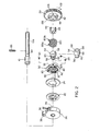
- the illustrated electromagnetically controlled spring clutch mechanism 18 includes an input rotary element 20, a unit sub-assembly 26 including a rotor 22 and an armature 24, and an electromagnetic means 28.
- the electromagnetically controlled spring clutch mechanism 18 can be used in either of two arrangements by changing the sequence of mounting the input rotary element, the sub-assembly 26 and the electromagnetic means 28, namely in a first arrangement (shown in Figs.
- the electromagnetic means 28 disposed on one end portion of the small-diameter portion 10a of the supporting shaft 10 has a core 30 and a coil assembly 32 received in the core 30, and the core 30 is rotatably mounted on the small-diameter portion 10a (see Fig.1).
- An engaging portion 36 is provided on the peripheral surface of the core 30, and a notch 38 is formed in the engaging portion 36.
- An engaging projection 40 is provided in the vertical rear plate 4 by bending part of it rearwardly, and held in engagement with the notch 38 of the engaging portion 36 (see Fig.1). Hence, the electromagnetic means 28 is not turned by the rotation of the supporting shaft 10.
- the details of the electromagnetic means 28 will be described hereinbelow.
- An input rotary element which is disposed on the other end portion of the small-diameter portion 10a and can be constructed as, for example, a gear 20, is rotatably mounted on the small-diameter portion 10a.
- An annular hub portion 42 is formed on one surface (the left surface in Figs. 1 and 2) of the gear 20 as a unit, and a first cylindrical boss member 44 is received within the hub portion 42.
- the first boss member 44 is adapted to rotate as a unit with the gear 20 by inserting the projection 48 formed on the end surface of the first boss member 44 into a through-hole 46 formed in the side surface of the gear 20.
- the first boss member 44 extends forwardly in the front-back direction towards a second boss member 54 to be described.
- the first boss member 44 may be formed integrally with the gear 20.
- the gear 20 is drivingly connected to a driving source, such as an electric motor, via a suitable gear mechanism, also not shown, and is rotated in a predetermined direction by the driving source.
- a retaining member 49 for preventing disengagement of the gear 20, etc. is mounted on that side of the small-diameter portion 10a of the supporting shaft 10 which is outwardly of the side of mounting the gear 20 (which is on the right in Fig.1).
- the sub-assembly 26 disposed on an intermediate portion of the small-diameter portion 10a, namely between the electromagnetic means 28 and the gear 20, comprises the rotor 22, the armature 24, a biasing spring member 50, a supporting member 52 and the second boss member 54, which constitute one sub-assembly unit.
- the second boss member 54 has a small-diameter portion 56 formed at its one end portion (the left end portion in Figs. 1 to 3), a large-diameter portion 58 formed at its other end portion (the right end portion of Figs. 1 to 3), and a medium-diameter portion 60 provided in its intermediate portion.
- a pair of notches 62 defining a pin receiving portion is formed in the small-diameter portion 56 of the second boss member 54.
- the second boss member 54 is adapted to rotate as a unit with the small-diameter portion 10a by bringing both end portions of a pin member 66 received in a pin. hole 64 (Fig2) extending through the small-diameter portion 10a of the supporting shaft 10 into engagement with the notches 62 (Figs.1 and 4).
- a pair of notches 68 defining a pin receiving portion are formed on the other end portion of the second boss member 54 - (Fig.2).
- the pair of notches 68 is utilized when the illustrated electromagnetically controlled spring clutch mechanism 18 is used according to the second arrangement shown in Fig.9.
- both end portions of the pin member 66 received in the pin hole 64 are brought into engagement with the pair of notches 68. Accordingly, when the clutch mechanism 18 is used only according to the first arrangement (Figs. 1 to 4), the notches 68 may be omitted.
- the notches 62 may be omitted.
- the rotor 22 comprises an annular plate having an annular hub portion 70, an annular rim portion 72 located outwardly of the annular hub portion 70, and a connecting portion 74 interconnecting the annular hub portion 70 and the annular rim portion 72.
- the rotor 22 is fixed to one end of the second boss member 54 by forcing the annular hub portion 70 onto the small-diameter portion 56 of the second boss member, so that it rotates as a unit with the second boss member 54 and therefore with the supporting shaft 10.
- a pair of notches 76 is formed in the inner circumferential edge of the annular hub portion 70 of the rotor 22 in relation to the fixing of the rotor 22 to the small-diameter portion 56 of the second boss member 54.
- the notches 76 formed in the rotor 22 define a pin receiving portion in co-operation with the notches 62 formed in the second boss member 54, and as shown in Fig.
- the two opposite end portions of the pin member 64 mounted on the small-c g ameter portion 10a are received in the notches 62 and the notches 76 (therefore, when the rotor 22 is to be fixed to the small-diameter portion 56 of the second boss member 54, the notches 76 of the rotor 22 are kept in alignment with the notches 62 of the small-diameter portion 56, and the two are forced into engagement).
- the supporting member 52 of annular configuration is rotatably mounted on the medium-diam eter portion 60 of the second boss member 54.
- An annular flange 77 is formed on the inner circumferential edge of one end surface (the left surface in Figs. 1 to 3) of the supporting member 52
- the supporting member 52 is formed of a light-weight plastics material.
- the armature 24 located opposite to one surface (the right surface in Figs. 1 to 3) of the rotor 22 is an annular plate having substantially the same outside diameter as the diameter of the annular portion 72 of the rotor 22, and is mounted on the supporting member 52 via the biasing spring member 50.
- the biasing spring member 50 is mounted on the annular flange 77 of the supporting member 52, and its annular central portion 78 is fixed to one end surface of the supporting member 52 in a manner to be described.
- the illustrated biasing spring member 50 has a plurality of (three in the illustrated embodiment) legs 80 extending in a sickle shape outwardly from the annular central portion 78, and the free end portions of the projecting legs 80 are fixed individually to one surface of the armature 24 (that surface which is opposite to the surface facing the rotor 22) by fastener members 84, such as rivets.
- the biasing spring member 50 serves to bias the armature resiliently away from one surface of the rotor 22.
- the biasing spring member 50 is fixed to the supporting member 52 as follows:
- the illustrated unit assembly 18 further includes a plate-like spring-fixing member.
- the illustrated spring-fixing member is an annular plate member 86 whose shape corresponds nearly to the shape of the annular central portion 78 of the biasing spring member 50.
- On the peripheral edge portion of the plate mamber 86 several (three in the illustrated embodiment) circumferentially spaced engaging tabs 88 are provided by partly bending it.
- several (three in the illustrated embodiment) reception holes 90 are formed in the annular central portion 78 of the biasing spring member 50 and correspond respectively to the engaging tabs 88, and through-holes 92 are formed in the supporting member 52 correspondingly to the reception holes 90.
- the engaging tabs 88 of the plate member 86 project to the other side of the supporting member 52 through the corresponding reception holes 90 of the biasing spring member 50 and the corresponding through-holes 92 of the supporting member 52 (as shown by solid lines in Fig.5).
- the annular central portion 78 of the biasing spring member 50 is fixed between the plate member 86 and the supporting member 52.
- the engaging tabs 88 are brought into engagement with the supporting member 52 in the manner shown on an enlarged scale in Fig.5. Specifically, it is preferred to enlarge the right end portion (the right end portion in Figs. 1 to 3 and 5) of each of the through-holes 92 and to accommodate the deformed portion of each engaging tab 88 in the enlarged portion 92a of the through-hole 92. By so doing, an assembled unit composed of the supporting member 52, the biasing spring member 50 and the plate member 86 can be reduced in size.
- the enlarged portion 92a is provided in the through-hole 92
- a press tool such as a punch
- the engaging tabs 88 concave so that its end surface 100 defines an arcuate surface.
- the projecting parts of the engaging tabs 88 which project as indicated by solid lines in Fig.5 can be deformed by the action of the press tool 108 to the state shown by one-dot chain lines in Fig.5, and the deformed portions can be accurately engaged with the enlarged portions 92a of the through-holes 92.
- circumferentially spaced projections 94 are further provided on one end surface of the supporting member 52, and circumferentially spaced openings 96 defining projection-receiving portions are provided in the annular central portion 78 of the biasing spring member 50 to correspond to the projections 94.
- the tip portion of each of the projections 94 extends through the respective opening 96 of the biasing spring member 50, further extends out towards one surface of the rotor 22 beyond the plate member 86 and the armature 24, and contacts or approaches one surface of the rotor 22 (see Fig.4).
- arcuate notches 98 corresponding to the openings 96, are formed on the peripheral edge portion of the plate member 86 in relation to the extending of the projections 94 as stated above. Accordingly, the projections 94 are respectively received in the openings 96 and the notches 98 and act to transmit the driving force between the supporting member 52 and the biasing spring member 50 (in other words, they act to receive a circumferential load, i.e. a load in the rotating direction, generated between the supporting member 52 and the biasing spring member 50), and increases the response characteristics of the clutch mechanism 18 as will be described hereinafter.
- the end portion of the annular flange 77 of the supporting member 52 also to project beyond the biasing spring member 50 and the plate member 86 and-for its end to contact or approach one surface of the rotor 22.
- the end -surfaces of the projections 94 and the end surface of the annular flange 77 define substantially the same plane substantially parallel to one surface of the rotor 22 (see Fig.4).
- a coil spring means 100 is received over the first boss member 44 fitted in the gear 20 and over the other end portion, i.e. the large-diameter portion 58, of the second boss member 54 of the sub-assembly 26.
- the large-diameter portion 58 of the second boss member 54 extends towards the first boss member 44, and the end surfaces of the two boss members 44 and 54 contact or approach each other.
- the outside diameter of the large-diameter portion 58 is substantially equal to the outside diameter of the first boss member 44, and the coil spring means 100 straddles across the large-diameter portion 58 and the first boss member 44.
- the coil spring means 100 is wound in the right-hand direction as viewed from the left side of Figs. 1 and 2 (therefore, in such a direction that it contracts when, during rotation of the gear 20 in the direction of an arrow 102, a force acts on the supporting member 52 so as to tend to withhold its rotation, and the supporting member is rotated relative to the gear 20).
- One end 100a of the coil spring means 100 is linked to the supporting member 52 by being inserted into a notch 104 formed in the other end portion of the supporting member 52 (i.e., one of a plurality of circumferentially spaced notches 104 in the illustrated embodiment).
- Its other end 100b is linked to the gear 20 by being inserted into a notch 106 (one of four circumferentially spaced notches 106 in the illustrated embodiment) formed in the annular hub portion 42 of the gear 20.
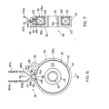
- the illustrated electromagnetic means 28 includes the cylindrical field core 30, the coil assembly 32 and a protective member 112.
- the core 30 has a nearly circular end wall 113 with a circular opening formed centrally thereof.
- Cylindrical outside and inside walls 114 and 115 each extending towards one side (to the right in Fig.7) are provided in the outer circumferential portion and inner circumferential portion respectively of the end wall 113, and one end surface of the field core 30 is opened.
- a securing opening 116 opened to the aforesaid one end surface of the core 30 is formed in the outside wall 114.
- the securing opening 116 is substantially rectangular and extends from one open end surface of the core 30 towards its other end and terminates at the inner surface of the end wall 113 (Figs. 7 and 8).
- a shoulder portion 118 is provided at two opposite sides defining the side surfaces of the securing opening 116 of the outside wall 114 (Figs. 6 and 8). The shoulder portion 118 extends from one end to the other end of the core 30 in the mounting direction of the protective member 112 to be described.
- a fixing projection 120 slightly projecting radially outwardly is provided in the outer surface of the inside wall 115 of the core 30 (that surface which faces the inner surface of the outside wall 114).
- three projections are provided at circumferentially spaced intervals on the inner wall 115.
- the projections 120 are preferably of such a shape that the amount of their radially outward projection increases progressively towards the mounting direction of the coil assembly 32 to be described.
- a bush-like bearing member 122 is fixed to the inner surface of the inside wall 115 of the core 30, and the engaging portion 36 having the notch 38 is provided on the outside surface of the outside wall 114.
- the core 30 having the aforesaid structure can be easily formed as a one-piece unit by sintering. By forcing the bearing member 122 into the inside wall of the core 30 moulded by sintering, the core 30 is built in the form shown in Fig.8.
- the coil assembly 32 includes a bobbin 130, and a coil member 132 wound on the bobbin 130.
- the bobbin 130 has a hollow sleeve portion 134 and annular flange portions 136a and 136b provided in opposite ends of the sleeve portion 134, and is formed as a one-piece unit from a synthetic resin or ceramics.
- the coil member 132 as shown in Fig.7, is wound on the peripheral surface of the sleeve portion 134 of the bobbin 130 and located between the flange portions 136a and 136b. As shown in Rg.8, the coif member 132 wound on the bobbin 130 is covered with a tape-like seal member 138, and only its two end portions are exposed.
- Lead wires 140a and 140b constituting connecting wire portions are connected to both end portions of the coil member 132, and by connecting the lead wires 140a and 140b, the coil assembly 32 is built in the form shown in Rg.8.
- a locating projection 142 projecting radially outwardly is provided in the peripheral edge of at least one of the flange portions 136a and 136b.
- the locating projection 142 is provided in the flange portion 136a as shown in the illustrated embodiment.
- the protective member 112 has a main body portion 144.
- the main body portion 144 has a rectangular cross-sectional surface and includes a radially extending through-hole 146 formed centrally thereof and outwardly extending engaging projections 148 provided respectively on two opposite surfaces of one end portion of the main body.
- the protective member 112 of such a structure can be formed, for example, as a one-piece unit from a synthetic resin or ceramics.
- the electromagnetic means 28 (Fig.2) is built in the form shown in Ftgs. 6 and 7 by assembling the core 30, the coil assembly 32 and the protective member 112 by the following procedure.
- a vinyl resin-sheathed electric wire is cut to a given length, and a pair of lead wires 140a and 140b is formed.
- connecting terminals 150a and 150b are press- bonded to end portions of the lead wcres140a and 140b respectively. Since each of the lead wires 140a and 140b has nothing attached to its ends, the press bonding of the connecting terminals 150a and 150b can be carried out easily and simply. Hence, the press-bonding step can be easily automated.
- the coil assembly 106 is built in the form shown in Fig.8.
- the lead wires 140a and 140b (constituting the connecting portion of the coil member 132) connected to the coil member 132 are inserted into the through-hole 146 of the protective member 112 to position the protective member 112 at the other end portions of the lead wires 140a and 140b. Then, the protective member 112 is fitted in the securing opening 116 formed in the core 30, and the coil assembly 32 is mounted in position within the core 30.
- the main body portion 144 of the protective member 112 is brought into alignment with the securing opening 116 at the aforesaid one end surface of the core 30 and the engaging projection 148 of the protective member 112 is also brought into alignment with the shoulder portions 118 provided at the sides defining the securing opening 116 of the core 30.
- the bobbin 130 is positioned between the inside wall 115 and the outside wall 114 of the core 30 at the aforesaid one end surface side of the core 30, and the locating projection 142 of the bobbin 130 is brought into alignment with the shoulder portions 118 provided in the core 30.
- the protective member 112 is inserted into the securing opening 116 in its mounting direction, namely to the left in Fig.
- the bobbin 130 is forced into the core 30 through the aforesaid open end surface in its mounting direction, namely to the left in Fig.7.
- the electromagnetic means is built as shown in Figs. 6 and 7.
- the main body portion 144 of the protective member 112 is thus situated in the securing opening 116 and projects outwardly of the outside wall 114 of the core 30, whereby the lead wires 140a and 140b are securely prevented from making direct contact with that edge portion of the core which defines the securing opening 116.
- the engaging projection 148 of the protective member 112 abuts against the shoulder portions 118 to prevent the protective member 112 from slipping off from the opening 116.
- the fixing projections 120 provided in the inside wall 115 of the core 30 act on the inner surface of the sleeve portion 134 of the bobbbin 130 to prevent the bobbin 130, and therefore the coil assembly 32, from slipping off.
- the coil assembly is fixed by caulking part of the inside wall of the core, and therefore, a special tool for this is required. In the specific embodiment of the present invention, however, no such special tool for exclusive use is required since the coil assembly 32 is force-fitted into the core 30. The assembling of the core 30 is therefore easier and simpler.
- the fixing projections 120 may be provided on the inner circumferential surface of the sleeve portion 134 of the bobbin 130 instead of providing them in the inside wall 114 of the core 30. To fix the coil assembly 32 more firmly, it is possible to fix the bobbin 130 together with the fixing projections 120 by means of an adhesive. When the coil assembly 32 has been fitted, the locating projection 142 provided in the flange portion 136a of the bobbin 130 is positioned at the shoulder portions 118 at one end portion of the core 30. Hence, the protective member 112 can be accuratley prevented from slipping off from the securing opening 116, and is fitted exactly in the securing opening 116 in the state shown in Figs 6 and 7. As can be easily understood from Figs.
- the protective member 112 can be fitted in position into the core 30 through the securing opening 116 formed in the core 30 while the protective member 112 is being attached to the lead wires 140a and 140b of the coil member 132. Accordingly, the mounting procedure in accordance with this invention can obviate the step of leading out a connecting wire portion in the prior art (in the prior art, a hole is formed in the outside wall of the core and the connecting wire portions are led out through the hole), and the step of forcing the protective member in the prior art (in the prior art, the protective member attached to the connecting wire portion is forced into the hole formed in the outside wall of the core). Consequently, the assembling of the electromagnetic means 28 is easy and simple, and can conveniently be automated.
- electromagnetic means 28 described above can be used for the electromagnetically controlled spring clutch mechanism 18, and can also be applied to other various electromagnetic clutch mechanisms.
- the clutch mechanism 18 is comprised of substantially four component sub-assemblies or elements, i.e. the electromagnetic means 28, the sub-assembly 26, the coil spring means 100 and the gear 20, as can be understood easily from the foregoing description.
- the clutch mechanism can be used in the first arrangement.
- the electromagnetic means 28 is first mounted, and then the pin member 66 is fitted in the pin hole 64 of the small-diameter portion 10a (the pin member 66 has a length slightly larger than the diameter of the small-diameter portion 10a, and therefore, when fitted in position, its two ends project from the small-diameter portion 10a as indicated in Fig.4).
- the sub-assembly 26 is next mounted, and the two end portions of the pin member 66 are positioned in the pin-receiving portion defined by the notches 62 of the second boss member 54 and the notches 76 of the rotor 22.
- One end portion of the coil spring means 100 is then placed over the large- " diameter portion 58 of the second boss member 54, and its one end 100a is inserted into the notch 104 of the supporting member 52.
- the gear 20 is then mounted so that the first boss member 44 which is attached to the gear 20, is positioned in the other end portion of the coil spring means 100.
- Its other end 100b is inserted into the notch 106 formed in the annular hub portion 42 of the gear 20, and thereafter, the retaining member 49 is fixed in engagement with the other end (the right end in Fig.1) of the small-diameter portion 10a.
- these sub-assemblies and elements are mounted in position on the small-diameter portion 10a of the supporting shaft 10. Since the number of sub-assemblies and mounting elements is small, the number of assembling steps is decreased, and the assembly can be effected easily and rapidly.
- the coil assembly 32 of the electromagnetic means 28 is disposed on the outboard side of the rotor 22, and the electromagnetic means 28 is prevented from rotation by the engaging projection 40.
- the second boss member 54 and the rotor 22 rotate as a unit with the supporting shaft 10 via the pin member 66, and the supporting member 52 and the armature 24, the biasing spring member 50 and the plate member 86 mounted on it are rotatable with respect to the second boss member 54, and therefore, to the supporting shaft 10.
- the gear 20 and the first boss member 44 attached to it are rotatable with respect to the supporting shaft 10.
- the electromagnetic means 28 When an electric current is supplied to the coil assembly 32 in the first arrangement, the electromagnetic means 28 is energized. As a result. by the magnetic attracting force of the electromagnetic means 28, the armature 24 moves to the left in Fig.1 against the resilient biasing action of the biasing spring member 50, and is magnetically attracted to one surface of the rotor 22, whereby the armature 24 and the rotor 22 are kept in connection.
- the gear 20 is rotated in the direction of the arrow 102 (Fig.2), and the supporting member 52 is also rotated in the same direction via the coil spring means 100 (the biasing spring member 50 and the armature 24 are also rotated as a unit with the supporting member 52).
- the rotating force of the gear 20 is transmitted to the supporting shaft 10 to rotate the supporting shaft 10, and therefore, the timing roller 12 mounted on it, in the direction of arrow 102 (Fig.2) incident to the rotation of the gear 20, whereby a copy paper sheet is conveyed in a required manner.
- the electromagnetic means 28 When the supply of current to the coil assembly 32 is stopped, the electromagnetic means 28 is de-energized. As a result, the armature 24 moves to the right in Fig.1 away from one surface of the rotor 22 by the resilient biasing action of the biasing spring member 50, and the aforesaid connection between the armature 24 and the rotor 22 is cancelled (in other words, the armature 24 returns to the position shown in Fig.1 by the action of the biasing spring member 50). At the instant of returning the armature 24, the armature is moved away from the one surface of the rotor 22 by the resilient biasing action of the biasing spring member 50 interposed between the supporting member 52 and the armature 24.
- the projections 94 provided on one end surface of the supporting member 52 are in contact with, or in proximity to, one surface of the rotor 22, it will be easily understood from Fig.4 that when the armature 24 is slightly tilted, the forward end surface of one projection 94 makes contact with one surface of the rotor 22, and therefore, a reduction in response characteristics due to the contacting of the armature 24 with one surface of the rotor 22 can be effectively prevented. Furthermore, since in the illustrated embodiment, the end of the annular flange 77 of the supporting member 52 is also kept in contact with, or in proximity to, one surface of the rotor 22, the play of the supporting member 52 can be reduced and the deterioration of response characteristics can further be prevented.
- the supporting member 52 When the connection between the armature 24 and the rotor 22 is cancelled, the supporting member 52 is further turned a little in the direction of arrow 102 by the resilient force of the coil spring means 100 which has been accumulated during the aforesaid transmission of the driving force, and the coil. spring means 100 is expanded. At the time of expanding the coil spring means 100, the supporting member 52 is rotatably mounted on the second boss member 54. Since only the biasing spring member 50, the armature 24 and the plate member 86 are mounted on the supporting member 52, the supporting member 52 is rotated easily and rapidly by the resilient force of the coil spring means 100 without undergoing high resistance.
- the number of mounting elements can be greatly decreased as compared with the prior art, and the distance between the rotor 22 and the armature 24, which is of particular importance, can be maintained constant.
- the plate member 86 acts substantially uniformly on almost all the area of the annular central portion 78 of the armature 24, whereby the annular central portion 78 can be fixed accurately across the plate member 86 and the supporting member 52, and the assembled unit composed of the biasing spring member 50, the supporting member 52, and the plate member 86 can be reduced in size. Furthermore, as a result of the fixation of the armature 24 to one end surface of the supporting member 52 through the biasing spring member 50 as mentioned above, the deformation of the armature 24 resulting from its fixation to the supporting member 52 in the prior art can be prevented, and consequently, the response characteristics are also improved.
- the electromagnetically controlled spring clutch mechanism 18 can be used in the second arrangement shown in Fig.9 by mounting the electromagnetic means 28, the sub-assembly 26, the coil spring means 100 and the gear 20 in the following manner.
- the gear 20 is first mounted in such a manner that the first boss member 44 on which it is mounted extends to the right in Fig.9.
- the pin-member 66 is fitted in the pin hole 64 of the small-diameter portion 10a.
- the other end portion of the coil spring means 100 is then placed over the first boss member 44 attached to the gear 20, and its other end 100b is inserted into the notch 106 formed in the annular boss portion 42 of the gear 20.
- the sub-assembly 26 is mounted such that the second boss member 54 faces the first boss member 44.
- the large-diameter portion 58 of the second boss member 54 of the sub-assembly 26 is positioned within one end portion of the coil spring means 100, and both end portions of the pin member 66 are kept in engagement with the pin-receiving portion defined by the notches 68 of the second boss member 54.
- the one end 100a of the coil spring means 100 is inserted into the notch 104 formed in the supporting member 52 of the sub-assembly 26.
- the electromagnetic means 28 is mounted in position (in the electromagnetic means 28, the engaging projection 40 provided in the vertical rear base plate 4 is received in the notch 38 of the engaging portion 36 provided in the core 30 as in the first arrangement), and the engaging member 49 is brought into engagement with the other end of the small-diameter portion 10a.
- the aforesaid sub-assemblies and elements are mounted in position on the small-diameter portion 10a of the supporting shaft 10 as shown in Fig.9.
- the coil assembly 32 of the electromagnetic means 28 is disposed on the other side of the rotor 22, and the rotation of the electromagnetic means 28 is prevented by the engaging projection 40 of the electromagnetic means 28, as in the first arrangement.
- the second boss member 54 and the rotor 22 rotate as a unit with the supporting shaft 10 via the pin member 66, and the supporting member 52 and the armature 24, biasing spring member 50 and plate member 86 mounted on it are rotatable with respect to the second boss member 54 and therefore the supporting shaft 10.
- the gear 20 and the first boss member 44 mounted on it are rotatable with respect to the supporting shaft 10.
- the electromagnetically controlled spring clutch mechanism 18 in the illustrated embodiment can be used in two arrangements by changing the sequence of mounting the sub-assemblies and elements, and can be used in a wide range of applications without changing the design.
Landscapes
- Engineering & Computer Science (AREA)
- Physics & Mathematics (AREA)
- Electromagnetism (AREA)
- General Engineering & Computer Science (AREA)
- Mechanical Engineering (AREA)
- Power Engineering (AREA)
- Braking Arrangements (AREA)
- Mechanical Operated Clutches (AREA)
Applications Claiming Priority (4)
| Application Number | Priority Date | Filing Date | Title |
|---|---|---|---|
| JP60078439A JP2686927B2 (ja) | 1985-04-15 | 1985-04-15 | 電磁制御ばねクラツチ機構 |
| JP78439/85 | 1985-04-15 | ||
| JP30129/86 | 1986-03-04 | ||
| JP1986030129U JPH0619865Y2 (ja) | 1986-03-04 | 1986-03-04 | 電磁クラッチ |
Publications (3)
| Publication Number | Publication Date |
|---|---|
| EP0202030A2 true EP0202030A2 (fr) | 1986-11-20 |
| EP0202030A3 EP0202030A3 (en) | 1987-01-28 |
| EP0202030B1 EP0202030B1 (fr) | 1990-07-18 |
Family
ID=26368414
Family Applications (1)
| Application Number | Title | Priority Date | Filing Date |
|---|---|---|---|
| EP86302782A Expired - Lifetime EP0202030B1 (fr) | 1985-04-15 | 1986-04-15 | Mécanisme d'embrayage électromagnétique |
Country Status (5)
| Country | Link |
|---|---|
| US (1) | US4704554A (fr) |
| EP (1) | EP0202030B1 (fr) |
| KR (1) | KR920010896B1 (fr) |
| CA (1) | CA1292196C (fr) |
| DE (1) | DE3672684D1 (fr) |
Cited By (4)
| Publication number | Priority date | Publication date | Assignee | Title |
|---|---|---|---|---|
| EP0242982A1 (fr) * | 1986-03-31 | 1987-10-28 | Mita Industrial Co. Ltd. | Mécanisme d'embrayage à ressort à commande électromagnétique |
| EP0285244A1 (fr) * | 1987-03-30 | 1988-10-05 | Mita Industrial Co. Ltd. | Mécanisme d'embrayage à ressort à commande électromagnétique |
| EP0422908A1 (fr) * | 1989-10-13 | 1991-04-17 | Mita Industrial Co., Ltd. | Mécanisme d'embrayage à ressort à commande électromagnétique |
| US5031745A (en) * | 1989-10-11 | 1991-07-16 | Mita Industrial Co., Ltd. | Electromagnetically controlled spring clutch mechanism |
Families Citing this family (6)
| Publication number | Priority date | Publication date | Assignee | Title |
|---|---|---|---|---|
| JP3330283B2 (ja) * | 1996-06-24 | 2002-09-30 | 京セラミタ株式会社 | 電磁クラッチ |
| KR101657726B1 (ko) * | 2008-11-17 | 2016-09-19 | 리텐스 오토모티브 파트너쉽 | 클러치 표면과 나선형 코일 클러치의 접속을 달성하기 위해 액추에이터를 포함하는 나선형 코일 클러치 조립체 |
| US8485331B2 (en) * | 2008-11-17 | 2013-07-16 | Litens Automotive Partnership | Driven accessory with low-power clutch for activating or de-activating same |
| US9097229B2 (en) * | 2010-06-14 | 2015-08-04 | Litens Automotive Partnership | Engine starter having clutch assembly for selective transmission of rotary power between a plate structure and a drive hub |
| CN103154546B (zh) | 2010-08-24 | 2015-06-24 | 利滕斯汽车合伙公司 | 离合从动装置和相关的离合机构 |
| EP3141772B1 (fr) * | 2015-09-09 | 2018-05-02 | Ogura Clutch Co., Ltd. | Embrayage électromagnétique |
Family Cites Families (8)
| Publication number | Priority date | Publication date | Assignee | Title |
|---|---|---|---|---|
| GB883608A (en) * | 1960-03-03 | 1961-12-06 | Normalair Ltd | Improvements relating to clutches |
| US3530416A (en) * | 1968-12-13 | 1970-09-22 | Warner Electric Brake & Clutch | Magnetic element for stationary field clutches |
| US4126215A (en) * | 1976-12-20 | 1978-11-21 | Facet Enterprises, Inc. | Sealed electromagnetic torque translating device |
| US4227600A (en) * | 1977-10-18 | 1980-10-14 | Sankyo Electric Company Limited | Electromagnetic clutches |
| US4296851A (en) * | 1979-06-01 | 1981-10-27 | Pitts Industries, Inc. | Drive hub with curved springs and drive keys for electro-magnetic clutch |
| US4321992A (en) * | 1980-07-07 | 1982-03-30 | Warner Electric Brake & Clutch Company | Wrap spring coupling with improved spring |
| US4386288A (en) * | 1981-05-26 | 1983-05-31 | The Superior Electric Company | Stepping motors having detented winding and winding method |
| JPH0751973B2 (ja) * | 1983-03-23 | 1995-06-05 | 三田工業株式会社 | 電磁制御ばねクラッチ機構 |
-
1986
- 1986-04-01 US US06/847,079 patent/US4704554A/en not_active Expired - Lifetime
- 1986-04-04 CA CA000505851A patent/CA1292196C/fr not_active Expired - Fee Related
- 1986-04-14 KR KR1019860002825A patent/KR920010896B1/ko not_active Expired
- 1986-04-15 DE DE8686302782T patent/DE3672684D1/de not_active Expired - Lifetime
- 1986-04-15 EP EP86302782A patent/EP0202030B1/fr not_active Expired - Lifetime
Cited By (5)
| Publication number | Priority date | Publication date | Assignee | Title |
|---|---|---|---|---|
| EP0242982A1 (fr) * | 1986-03-31 | 1987-10-28 | Mita Industrial Co. Ltd. | Mécanisme d'embrayage à ressort à commande électromagnétique |
| EP0285244A1 (fr) * | 1987-03-30 | 1988-10-05 | Mita Industrial Co. Ltd. | Mécanisme d'embrayage à ressort à commande électromagnétique |
| US5031745A (en) * | 1989-10-11 | 1991-07-16 | Mita Industrial Co., Ltd. | Electromagnetically controlled spring clutch mechanism |
| EP0422908A1 (fr) * | 1989-10-13 | 1991-04-17 | Mita Industrial Co., Ltd. | Mécanisme d'embrayage à ressort à commande électromagnétique |
| US5031744A (en) * | 1989-10-13 | 1991-07-16 | Mita Industrial Co., Ltd. | Electromagnetically controlled spring clutch mechanism |
Also Published As
| Publication number | Publication date |
|---|---|
| KR920010896B1 (ko) | 1992-12-21 |
| EP0202030B1 (fr) | 1990-07-18 |
| DE3672684D1 (de) | 1990-08-23 |
| US4704554A (en) | 1987-11-03 |
| CA1292196C (fr) | 1991-11-19 |
| KR860008384A (ko) | 1986-11-15 |
| EP0202030A3 (en) | 1987-01-28 |
Similar Documents
| Publication | Publication Date | Title |
|---|---|---|
| US4825988A (en) | Electromagnetically controlled spring clutch mechanism | |
| US4570768A (en) | Electromagnetically controlled spring clutch mechanism | |
| EP0202030B1 (fr) | Mécanisme d'embrayage électromagnétique | |
| EP0571050B1 (fr) | Mécanisme d'embrayage à ressort à commande électromagnétique | |
| US4793453A (en) | Electromagnetically controlled spring clutch mechanism | |
| US8418827B2 (en) | Driving device | |
| EP0370624B1 (fr) | Embrayage électromagnétique | |
| JPS61236930A (ja) | 電磁制御ばねクラツチ機構 | |
| EP0285244B1 (fr) | Mécanisme d'embrayage à ressort à commande électromagnétique | |
| US5038905A (en) | Electromagnetic clutch | |
| JP2832211B2 (ja) | 電磁制御ばねクラッチ機構 | |
| KR100370793B1 (ko) | 사무기기의 용지 픽업용 스프링 클러치 | |
| JP2832210B2 (ja) | 電磁制御ばねクラッチ機構 | |
| JP3592225B2 (ja) | コイル組立体及び電磁クラッチ | |
| JPS62224732A (ja) | 電磁制御ばねクラツチ機構 | |
| JP3365751B2 (ja) | 電磁クラッチ | |
| JP4524765B2 (ja) | 電磁クラッチ | |
| EP0249490A2 (fr) | Mécanisme de fixation d'une culasse pour embrayages électromagnétiques | |
| EP0416178B1 (fr) | Embrayage électromagnétique | |
| JPH0236979Y2 (fr) | ||
| KR200229789Y1 (ko) | 사무기기의 용지 픽업용 스프링 클러치 | |
| JP2000120727A (ja) | 電磁クラッチ | |
| JP2002031160A (ja) | 電磁クラッチ | |
| JP2001003959A (ja) | 電磁クラッチ | |
| JPH1182554A (ja) | 電磁クラッチ |
Legal Events
| Date | Code | Title | Description |
|---|---|---|---|
| PUAI | Public reference made under article 153(3) epc to a published international application that has entered the european phase |
Free format text: ORIGINAL CODE: 0009012 |
|
| AK | Designated contracting states |
Kind code of ref document: A2 Designated state(s): DE FR GB NL |
|
| PUAL | Search report despatched |
Free format text: ORIGINAL CODE: 0009013 |
|
| AK | Designated contracting states |
Kind code of ref document: A3 Designated state(s): DE FR GB NL |
|
| 17P | Request for examination filed |
Effective date: 19870307 |
|
| 17Q | First examination report despatched |
Effective date: 19880823 |
|
| GRAA | (expected) grant |
Free format text: ORIGINAL CODE: 0009210 |
|
| AK | Designated contracting states |
Kind code of ref document: B1 Designated state(s): DE FR GB NL |
|
| ET | Fr: translation filed | ||
| REF | Corresponds to: |
Ref document number: 3672684 Country of ref document: DE Date of ref document: 19900823 |
|
| PLBE | No opposition filed within time limit |
Free format text: ORIGINAL CODE: 0009261 |
|
| STAA | Information on the status of an ep patent application or granted ep patent |
Free format text: STATUS: NO OPPOSITION FILED WITHIN TIME LIMIT |
|
| 26N | No opposition filed | ||
| PGFP | Annual fee paid to national office [announced via postgrant information from national office to epo] |
Ref country code: FR Payment date: 19980409 Year of fee payment: 13 |
|
| PGFP | Annual fee paid to national office [announced via postgrant information from national office to epo] |
Ref country code: NL Payment date: 19980428 Year of fee payment: 13 |
|
| PG25 | Lapsed in a contracting state [announced via postgrant information from national office to epo] |
Ref country code: NL Free format text: LAPSE BECAUSE OF NON-PAYMENT OF DUE FEES Effective date: 19991101 |
|
| PG25 | Lapsed in a contracting state [announced via postgrant information from national office to epo] |
Ref country code: FR Free format text: LAPSE BECAUSE OF NON-PAYMENT OF DUE FEES Effective date: 19991231 |
|
| NLV4 | Nl: lapsed or anulled due to non-payment of the annual fee |
Effective date: 19991101 |
|
| REG | Reference to a national code |
Ref country code: FR Ref legal event code: ST |
|
| PGFP | Annual fee paid to national office [announced via postgrant information from national office to epo] |
Ref country code: DE Payment date: 20010409 Year of fee payment: 16 |
|
| PGFP | Annual fee paid to national office [announced via postgrant information from national office to epo] |
Ref country code: GB Payment date: 20010411 Year of fee payment: 16 |
|
| REG | Reference to a national code |
Ref country code: GB Ref legal event code: IF02 |
|
| PG25 | Lapsed in a contracting state [announced via postgrant information from national office to epo] |
Ref country code: GB Free format text: LAPSE BECAUSE OF NON-PAYMENT OF DUE FEES Effective date: 20020415 |
|
| PG25 | Lapsed in a contracting state [announced via postgrant information from national office to epo] |
Ref country code: DE Free format text: LAPSE BECAUSE OF NON-PAYMENT OF DUE FEES Effective date: 20021101 |
|
| GBPC | Gb: european patent ceased through non-payment of renewal fee |
Effective date: 20020415 |