EP0202117B1 - Doppeltfokussierende Massenspektrometer - Google Patents
Doppeltfokussierende Massenspektrometer Download PDFInfo
- Publication number
- EP0202117B1 EP0202117B1 EP86303667A EP86303667A EP0202117B1 EP 0202117 B1 EP0202117 B1 EP 0202117B1 EP 86303667 A EP86303667 A EP 86303667A EP 86303667 A EP86303667 A EP 86303667A EP 0202117 B1 EP0202117 B1 EP 0202117B1
- Authority
- EP
- European Patent Office
- Prior art keywords
- sector
- magnetic
- electrostatic
- sectors
- boundary
- Prior art date
- Legal status (The legal status is an assumption and is not a legal conclusion. Google has not performed a legal analysis and makes no representation as to the accuracy of the status listed.)
- Expired - Lifetime
Links
- 230000005291 magnetic effect Effects 0.000 claims description 114
- 150000002500 ions Chemical class 0.000 claims description 79
- 239000003302 ferromagnetic material Substances 0.000 claims description 2
- 238000000034 method Methods 0.000 description 20
- 238000010884 ion-beam technique Methods 0.000 description 19
- 238000013461 design Methods 0.000 description 16
- 230000004075 alteration Effects 0.000 description 12
- 238000004458 analytical method Methods 0.000 description 7
- 238000004519 manufacturing process Methods 0.000 description 7
- 230000003287 optical effect Effects 0.000 description 7
- 239000000126 substance Substances 0.000 description 6
- 238000004885 tandem mass spectrometry Methods 0.000 description 6
- 238000010276 construction Methods 0.000 description 5
- 238000001228 spectrum Methods 0.000 description 5
- 238000012546 transfer Methods 0.000 description 5
- XEEYBQQBJWHFJM-UHFFFAOYSA-N Iron Chemical compound [Fe] XEEYBQQBJWHFJM-UHFFFAOYSA-N 0.000 description 4
- 230000008901 benefit Effects 0.000 description 4
- 238000010586 diagram Methods 0.000 description 4
- 238000002474 experimental method Methods 0.000 description 4
- 230000005294 ferromagnetic effect Effects 0.000 description 4
- 238000001914 filtration Methods 0.000 description 4
- 230000009471 action Effects 0.000 description 3
- 239000012634 fragment Substances 0.000 description 3
- 238000013467 fragmentation Methods 0.000 description 3
- 238000006062 fragmentation reaction Methods 0.000 description 3
- 239000007789 gas Substances 0.000 description 3
- 238000004949 mass spectrometry Methods 0.000 description 3
- 239000011159 matrix material Substances 0.000 description 3
- 230000035945 sensitivity Effects 0.000 description 3
- RYGMFSIKBFXOCR-UHFFFAOYSA-N Copper Chemical compound [Cu] RYGMFSIKBFXOCR-UHFFFAOYSA-N 0.000 description 2
- 230000015572 biosynthetic process Effects 0.000 description 2
- 239000000919 ceramic Substances 0.000 description 2
- 229910052802 copper Inorganic materials 0.000 description 2
- 239000010949 copper Substances 0.000 description 2
- 238000012937 correction Methods 0.000 description 2
- 230000007547 defect Effects 0.000 description 2
- 230000000694 effects Effects 0.000 description 2
- 230000006872 improvement Effects 0.000 description 2
- 229910052742 iron Inorganic materials 0.000 description 2
- 239000000203 mixture Substances 0.000 description 2
- 230000009467 reduction Effects 0.000 description 2
- XLYOFNOQVPJJNP-UHFFFAOYSA-N water Substances O XLYOFNOQVPJJNP-UHFFFAOYSA-N 0.000 description 2
- 230000001133 acceleration Effects 0.000 description 1
- 238000007630 basic procedure Methods 0.000 description 1
- 230000005540 biological transmission Effects 0.000 description 1
- 238000000451 chemical ionisation Methods 0.000 description 1
- 150000001875 compounds Chemical class 0.000 description 1
- 238000011109 contamination Methods 0.000 description 1
- 238000001816 cooling Methods 0.000 description 1
- 230000001419 dependent effect Effects 0.000 description 1
- 238000009795 derivation Methods 0.000 description 1
- 239000006185 dispersion Substances 0.000 description 1
- 230000005686 electrostatic field Effects 0.000 description 1
- 238000010265 fast atom bombardment Methods 0.000 description 1
- 239000011261 inert gas Substances 0.000 description 1
- 239000012212 insulator Substances 0.000 description 1
- 238000011835 investigation Methods 0.000 description 1
- 230000008569 process Effects 0.000 description 1
- 238000005086 pumping Methods 0.000 description 1
- 238000012552 review Methods 0.000 description 1
- 238000007493 shaping process Methods 0.000 description 1
- 238000004904 shortening Methods 0.000 description 1
- 230000003595 spectral effect Effects 0.000 description 1
Images



Classifications
-
- H—ELECTRICITY
- H01—ELECTRIC ELEMENTS
- H01J—ELECTRIC DISCHARGE TUBES OR DISCHARGE LAMPS
- H01J49/00—Particle spectrometers or separator tubes
- H01J49/26—Mass spectrometers or separator tubes
- H01J49/28—Static spectrometers
- H01J49/32—Static spectrometers using double focusing
Definitions
- This invention relates to mass spectrometers, and in particular to mass spectrometers which incorporate a magnetic sector analyser.
- a beam of ions is deflected by a magnetic field by an amount dependent on the mass to charge ratio (m/z) of the ions.
- ions from a source are first accelerated through an electrical potential V to an energy of where v is the velocity of the ion after acceleration.
- V is the velocity of the ion after acceleration.
- the ions experience a centrifugal force where r is the radius of curvature of the path of the ions in the magnetic field.
- the force exerted by it is Bzv, so that Combining equations [1] and [2],
- r is fixed by the use of 2 narrow slits in fixed positions relative to the magnetic field, and V is held constant, so that ions of different m/z ratios are selected by changing the magnetic field B.
- a magnetic field can also be arranged to provide a direction focusing effect on a beam of ions, in the same way as does an optical lens with a beam of light.
- an electrostatic analyser can also provide direction focusing of the beam providing that the object and image slits are correctly positioned and the field itself is properly shaped. Use of this focusing behaviour clearly enhances the resolution of the analyser.
- High resolution mass spectrometers therefore employ both an electrostatic sector and a magnetic sector analyser in series in order to provide both mass and energy filtration of the ion beam. It is well known that in spectrometers of this type particular combinations of electrostatic and magnetic sectors also result in velocity focusing of an ion beam as well as direction focusing; in other words an ion beam of one m/z ratio entering the first analyser within a certain range of incident angles and having an energy lying within a certain range of values will be accurately focused to the same point on the exit focal plane of the second analyser.
- Mass spectrometers of this type are known as double focusing mass spectrometer, and are capable of resolutions in excess of 100,000 (10% valley definition).
- Spectrometers having Mattauch - Herzog geometry do not form a real intermediate image. Instead, the image of the first sector is arranged to be at infinity, and the object distance of the second analyser is also arranged to be infinity, so that a real image is formed by the second analyser at a distance equal to its focal length.
- This arrangement in general provides a smaller instrument than the Nier-Johnson geometry for a similar performance and is well adapted to provide an extended focal plane along which a photographic plate or a multichannel detector can be positioned so that the entire spectrum can be recorded simultaneously.
- the focusing actions described above are imperfect, and suffer from aberrations, as do those of simple optical lenses. Many of these aberrations can be predicted theoretically and can be minimized by further selection of the positions and shapes of the fields and by fixing certain critical dimensions. Additional magnetic and/or electrostatic lenses can also be incorporated to correct certain of the aberrations. Other aberrations in focusing behaviour, particularly those due to the fringing fields at the entrance and exit of the analysers, are difficult to predict but can be minimized by experimental adjustments.
- a technique of mass spectrometry which is gaining rapidly in popularity is that of tandem mass spectrometry, often abbreviated to MS/MS. It is used to study the fragmentation of ions, which is usually induced by causing them to collide with molecules of an inert gas in a collision cell, producing fragment ions of various mass/charge ratios and kinetic energies.
- MS/MS tandem mass spectrometry
- a typical tandem mass spectrometry experiment involves the production of a primary ion beam from a sample, filtration of the beam to produce a beam of ions of a particular m/z value, the passage of this beam through a collision gas cell to induce fragmentation of the ions, and the subsequent mass or kinetic energy analysis of the fragment ions.
- Experiments of this kind yield useful information on the chemical composition of the sample, and can provide a very specific and sensitive method for the determination of trace components in a complex mixture.
- JP-A-5963652 describes a collision mass spectrometer in which the first two sectors BE produce a focused image which then acts as the object for a third (B) sector which is used to mass analyse the products of the collision.
- the three sector BEB and EBE combinations comprise a conventional two sector high resolution primary stage and a low resolution single sector mass or energy analyser following the collision cell. If such an instrument is used without the collision cell, so that the primary beam passes into the third sector, the final image is not velocity focused and consequently a lower resolution will be achieved in comparison with the resolution achievable at the velocity focused intermediate image.
- BEB instruments can also be configured with the collision cell after the first sector, so that a low resolution primary stage and a high resolution double focusing secondary stage are provided. Use of this type of instrument without the collision cell also produces a lower resolution final image than could be achieved with the second stage alone, because the image produced by the first stage is not velocity focused. Of course the resolution can be improved by fitting a narrow slit at the intermediate image position, but this clearly would reduce the transmission efficency of the instrument and hence its sensitivity.
- SU-A-993362 describes a mass spectrometer which cannot produce a velocity-focused image since the planes of mass and energy dispersion are perpendicular to one another.
- a well known difficulty encountered when using a magnetic sector mass spectrometer for organic chemical analysis is the limitation imposed on the speed of scanning the spectrum by the hysteresis of the magnet core.
- the difficulty of relating the actual mass/charge ratio being transmitted to the demanded mass during a fast scan seriously limits the maximum speed attainable. Indeed adequate results can be obtained only through the use of complicated electronic circuitry and by the introduction of reference samples to calibrate the mass scale, sometimes simultaneously with the sample. The selection of suitable reference samples often presents a severe problem.
- a mass spectrometer having a focusing sector array comprising sectors of the electrostatic type and sectors of the magnetic type, at least three of said sectors being so dimensioned and positioned so as to cooperate to form a velocity- and direction-focused image, said at least three sectors being so dimensioned and positioned as to form no velocity focused image within the array, and said at least three sectors comprise at least one magnetic sector and at least one electric sector arranged so that one said sector is adjacent to and between two sectors of the other type.
- a sector being adjacent to and between two other sectors of the other type it is meant that on the ion flight path the sectors immediately before and immediately after the sector in question are of the type other than that of the sector in question, ie. the sector sequence BEB or EBE exists.
- the invention provides a mass spectrometer having a focusing sector array comprising sectors of the electrostatic type and sectors of the magnetic type, at least three of said sectors being so dimensioned and positioned so as to cooperate to form a velocity- and direction-focused image, said at least three sectors being so dimensioned and positioned as to form no direction focused image within the array, and said at least three sectors comprise at least one magnetic sector and at least one electric sector arranged so that one said sector is adjacent to and between two sectors of the other type.
- the spectrometer of the invention comprises one magnetic analyser sector and two electrostatic analyser sectors, disposed in an EBE configuration so that no intermediate direction or velocity focused images are formed.
- the spectrometer is regarded as being divided into two parts by a plane at right angles to the motion of the ions through the spectrometer and which passes through the point of intersection of normals to the central trajectory of ions passing through the central magnetic sector analyser at the intersection of the entrance and exit boundaries of the magnetic field with said central trajectory, and which makes angles ⁇ m1 and ⁇ m2 respectively with each of said normals such that the trajectories of all ions of a particular m/z ratio but of different energies are parallel to each other at the points at which they cross said plane.
- r e1 is the radius of the 1st electrostatic analyser sector
- r e2 is the radius of the 2nd electrostatic analyser sector
- r m is the radius of the central magnetic analyser sector
- ⁇ e1 is the sector angle of the 1st electrostatic sector
- ⁇ e2 is the sector angle of the 2nd electrostatic sector
- ⁇ m1 , ⁇ m2 are as defined above
- ⁇ ' is the angle of inclination of the entrance boundary of the magnetic sector to the normal at the entrance boundary defined above
- ⁇ '' is the angle of inclination of the exit boundary of the magnetic sector to the normal at the exit boundary defined above
- d1 is the distance between the exit boundary of the first electrostatic sector and the entrance boundary of the magnetic sector, measured along the central trajectory
- d2 is the distance between the entrance boundary of the second electrostatic sector and the exit boundary of the magnetic sector, measured along the central trajectory.
- the angles ⁇ ' and ⁇ '' are equal to zero so that the spectrometer is constructed to satisfy the equations:- and
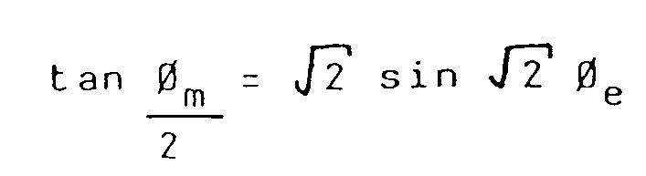
- a still further preferred form of the spectrometer has the radius of the magnetic sector (r m ) much greater than, e.g. 5 or more times, the radius of the electrostatic sectors (r e ) and the distance (d) between the sectors, so that the equation tan ⁇ m /2 ⁇ ⁇ 2 ⁇ sin ⁇ 2 ⁇ ⁇ e [12] is approximately satisfied.
- This embodiment is especially suited to use with an air cored magnet which has a limited magnetic field strength and therefore requires a large radius r m in order for the spectrometer to have adequate mass range.
- one electrostatic sector analyser and two magnetic sector analysers are disposed in a BEB configuration, so that no velocity focused images are formed between the sectors and both direction and velocity focusing is achieved by the combination of all three sectors.
- the spectrometer is regarded as being divided into two parts by a plane at right angles to the motion of the ions through the spectrometer, which passes through the intersection of projections of the boundaries of the electrostatic field, and which makes angles ⁇ e1 and ⁇ e2 with the projections of the entrance and exit boundaries, respectively, such that the trajectories of all ions of a particular m/z ratio but of different energies are parallel to each other at the points where they cross said plane.
- ⁇ m1 is the sector angle of the first magnetic analyser sector
- ⁇ m2 is the sector angle of the second magnetic analyser sector
- ⁇ e1 and ⁇ e2 are as defined above
- r m1 is the radius of the first magnetic analyser sector
- r m2 is the radius of the second magnetic analyser sector
- r e is the radius of the central electrostatic analyser sector
- d1 is the distance between the exit boundary of the first magnetic sector and the entrance boundary of the electrostatic analyser
- d2 is the distance between the entrance boundary of the second magnetic sector and the exit boundary of the electrostatic analyser
- ⁇ 1'' is the angle of inclination of the exit boundary of the first magnetic sector to the normal to the central trajectory of this sector at the point where the central trajectory cuts the magnetic sector exit boundary
- ⁇ 2' is the angle of inclination of the entrance boundary of the second magnetic analyser sector to the normal to the central trajectory of this sector at the point where the central trajectory cuts the magnetic sector exit boundary
- a spectrometer having these features therefore satisfies the equation: It is possible to use a similar method to design other multiple sector mass spectrometers which produce a final image which is velocity focused without any intermediate velocity focused images. First, the desired arrangement of sectors is divided into two parts by an imaginary plane so that each part contains at least one sector and at least part of another sector of the other type.
- the plane is drawn in such a way that the trajectories of all ions crossing it intersect it at 90°. Along this plane the angular deviation y1' is 0.
- the known transfer matrices for each section of the spectrometer from the ion source to the plane are then used to obtain y1' at the plane, which is then equated to 0.
- the part of the spectrometer on the other side of the plane is treated in the same way, and the critical relationship between the sectors needed for first order focusing and the production of a final velocity focused image can be found. It is obvious, however, that not every combination of sectors will permit such a plane to be drawn. Of those that will, it is thought that EBEBE and EEBEE combinations would have particularly useful properties, but others are not excluded.
- a spectrometer allows the construction of a double focusing spectrometer of high performance having a very high r m and relatively small ⁇ m . This is ideally suited to the use of a magnet with a non-ferromagnetic core.
- a further preferred version of the invention comprises a double focusing mass spectrometer as defined above comprising electrostatic lenses disposed between the ion source of the spectrometer and the entrance boundary of the first analyser sector of the array and between the exit boundary of the last analyser sector of the array and the ion detector, said electrostatic lenses being arranged to reduce the object distance of said first analyser and the image distance of said last analyser.
- the lenses permit substantial reduction of the object and image distances whilst allowing both direction and velocity focusing to be maintained.
- further electrostatic zoom lenses are provided in order to vary the effective width of the object and image slits of the spectrometer in order to eliminate the need for slits of adjustable width operable from outside the vacuum envelope of the spectrometer.
- the invention comprises a mass spectrometer as defined above in which said magnetic sector, or at least one of said magnetic sectors, is equipped with an electromagnet having a core of a non-ferromagnetic material.
- the electromagnet is air cored, and furthermore it preferably comprises two flat coils disposed either side of the plane in which the ions travel during their passage through the magnetic sector.
- the invention provides a mass spectrometer having double focusing properties which is suitable for use as a tandem mass spectrometer, and which is adapted to substantially reduce the spurious peaks which are frequently formed when a two sector double focusing mass spectrometer is used in this way. Furthermore, the invention provides a physically small mass spectrometer which has double focusing properties and in which the electrostatic analyser sector or sectors are so short that the plates forming them need not be curved, as in a conventional electrostatic analyser, thereby greatly simplifying their manufacture.
- a compact double focusing mass spectrometer of medium-high resolution can be constructed with a magnetic sector radius greater than 500 mm, which permits the use of an electromagnet with a low field strength (e.g. 0.1T) whilst still maintaining an adequate mass range for organic chemical analysis.
- This field strength can be obtained using an air-cored magnet, which has negligible hysteresis, allowing the entire mass range to be scanned much more quickly and reproducibly than is possible with a conventional iron cored magnet.
- the lack of hysteresis, and the consequent ease of relating the transmitted m/z ratio to the current through the magnet coils eliminates the need for frequent calibration of the mass range of the spectrometer by means of reference compounds.
- the presence of the electrostatic analyser on each side of the magnetic analyser in the preferred embodiment provides electrostatic filtration of the ion beam before and after mass selection in the magnet.
- tandem mass spectrometry experiments can be carried out without the formation of the spurious peaks which detract from tandem mass spectrometer experiments carried out on conventional two sector instruments, despite the lack of any filtration of the primary ion beam.
- the mass spectrometer of the invention behaves in the same way as an EBE type tandem mass spectrometer previously described in which the collision gas cell is located before the first analyser.
- a further simplification in construction which can be achieved in the preferred embodiment of the invention is a consequence of the very small sector angles of the electrostatic analysers which are required by the preferred embodiment.
- This means that the length of the sectors is very small compared with the radius of the ion beam path through them, so that in a practical design short straight plates can be used in place of the conventional cylindrical plates which are difficult to manufacture.
- This simplification greatly reduces the cost of manufacture of the spectrometer.
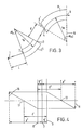
- ions from an ion source pass through slit S1 and are focused by electrostatic sector E to form a real image at slit S2 before passing between the plates of magnetic sector B to be focused at slit S3.
- ions from an ion source pass through slit S and are focused by electrostatic sector E and magnetic sector B on focal plane FP.
- y o is the y coordinate of the ion as it enters the sector
- y o ' is the angular deviation of its trajectory from the central trajectory of the analyser sector
- ⁇ is its deviation from the velocity of an ion travelling along the central trajectory
- ⁇ is its deviation in momentum from that of an ion travelling along the central trajectory.
- the coordinates of the ion as it leaves the sector or region of free space are defined as y1, y1', ⁇ and ⁇ .
- First order transfer matrices which relate the exit parameters to the entrance parameters for each sector and for free space are well known and can be expressed as below. Note that the z co-ordinates do not enter into the first order matrices.
- the y1' parameter of the point 5 is given by In equation [24], r m is taken as negative because the magnetic sector bends the ion beam in the opposite direction to that caused by the electrostatic sector, and ⁇ '' is the exit angle of part of the magnetic sector (at point 5).
- the second half of the spectrometer is a mirror image of the first half, and the condition for overall double focusing is simply given by equating the y1' parameters at point 5 to zero, assuming that the second half is treated in the same way as the first half already described, but starting at the ion detector.
- Equation [24] simplifies to In equation [25], ⁇ e1 ,r e1 ,d1 and ⁇ '1 are used to signify that the equation relates to the first part of the spectrometer. Therefore, An exactly similar treatment applied to the second part of the spectrometer (parameters ⁇ e2 , ⁇ m2 , d2,r e2 , ⁇ 2'), leads to equation [27], Equations [26] and [27] are identical to equations [7]and [8] stated previously, and define the essential relationships which have to be satisfied by a three sector spectrometer constructed according to the invention.
- l' is the distance from the mechanical boundary 7 to the image 10
- l'' is the distance from the mechanical boundary 7 to the object 11
- the first electrostatic sector E1 produces a virtual image V of the ion source I which serves as a virtual object for the magnetic sector B, so that the distance l e ' can be calculated once ⁇ m , ⁇ e , r m and r e are selected and a convenient value chosen for d.
- the distance l e ' can be calculated once ⁇ m , ⁇ e , r m and r e are selected and a convenient value chosen for d.
- le' may be as much as a factor of 10 smaller than lm', allowing the construction of a compact instrument with a high r m . If further shortening of le' is required, this can be achieved by means of additional conventional electrostatic lenses between the ion source and the entrance of the electrostatic sector.
- parameters r e and d are further selected to minimize second order aberrations in the overall double focusing behaviour. The derivation of the focusing equations should present no difficulty to those skilled in the art, following the basic procedure outlined above and using the standard second order matrices for each sector, end the method of minimizing the most important aberrations is well known in the art.
- the same design principles can be utilized even if the central sector is not a magnetic sector, of if there are an even number of sectors without any intermediate images.
- the procedure for the design of a BEB type spectrometer with overall double focusing follows the previous procedure almost exactly.
- Equation 33 can be derived from the transfer matrices following a similar procedure outlined for the EBE embodiment.
- the terms have the following significance: ⁇ m1 is the sector angle of the first magnetic sector 38, ⁇ m2 is the sector angle of the second magnetic sector 39, ⁇ e1 is the angle between the entrance boundary of the electrostatic sector 37 and plane 36.
- ⁇ e2 is the angle between the exit boundary of electrostatic sector 37 and plane 36
- r m1 is the radius of the first magnetic sector 38
- r m2 is the radius of the second magnetic sector 39
- r e is the radius of the electrostatic sector 37
- d1 is the distance between the exit of sector 38 and the entrance of sector 37
- d2 is the distance between the exit of sector 37 and the entrance of sector 38
- ⁇ 1'' is the angle between the exit boundary of said first magnetic sector and a normal to the central trajectory at its point of intersection with the exit boundary of said first magnetic sector
- ⁇ 2' is the angle between the entrance boundary of said second magnetic sector and a normal to the central trajectory at its point of intersection with the entrance boundary of said second magnetic sector.
- this method can be used to design spectrometers which have overall double focusing and any number of sectors, providing that at least one magnetic and at least one electrostatic sector are present, and either no intermediate image, or an intermediate image which is only direction focused and not velocity focused, is formed between the sectors.
- an ion source 15 generates a beam of ions which passes through the source slit electrode 36 and then an electrostatic zoom lens comprising electrodes 16 - 21.
- the ion source 15 may be of any suitable type, eg, electron bombardment, chemical ionization, or fast atom bombardment, and generates a beam of ions with an energy of typically between 2 and 5 keV.
- the ion source 15 produces a real object for the analyser section which is defined by the object slit of the spectrometer in electrode 36.
- the slit in this electrode may advantageously be made of adjustable width in order to vary the resolution of the spectrometer, as in a conventional magnetic sector mass spectrometer.
- the zoom lens comprises two three element conventional electrostatic lenses (electrodes 16,17 and 18, and electrodes 19, 20, 21) arranged in a known fashion in order to shorten the object distance of the spectrometer. Without this lens, the source slit electrode 36 would have to be positioned at point 14, greatly increasing the physical size of the spectrometer.
- the ion beam then passes through the first electrostatic sector analyser, comprising plates 22 and 34.
- electrodes 36, 16 - 21, and analyser 22, 34 are built in the form of a stack of plates on four ceramic rods mounted from a convenient flange of the spectrometer vacuum housing, and spaced apart by annular ceramic insulators.
- electrodes 16 - 21 and 36 comprise simple plate electrodes with a rectangular slit-like aperture for the ion beam to pass through, and with the dimensions of the aperture selected according to their function and to well established methods.
- the electrostatic analyser sector comprises two "half plates" of accurately controlled thickness maintained at a positive and negative potential, respectively, as in a conventional electrostatic analyser.
- the ion beam passes into the magnetic analyser sector 23, which in the preferred embodiment is between 500 and 2000 mm radius.
- a large radius permits the use of an air cored magnet, which may conveniently consist of two spiral coils placed respectively above and below the flight path of the ions.
- copper tape approximately 35 mm x 0.5 mm thick, is used to wind each coil. This allows several hundred amperes to be passed through each coil, resulting in a sufficiently strong magnetic field to permit the instrument to be used for organic chemical analysis.
- Water cooling of the coils is also desirable, and can be achieved by mounting them between hollow copper plates through which water is circulated.
- a nonferromagnetic former may also be used in the centre of each coil, and some improvement in field strength and field homogeneity can be achieved by shaping the coils to correspond approximately with the ion path through the magnetic sector.
- Control of the current through the magnet coils, and hence the mass selected by the spectrometer, can be carried out by any suitable method.
- Electrode 31 is the collector slit of the spectrometer and is preferably made of adjustable width in order to control the resolution of the spectrometer in conjunction with electrode 36.
- the collector electrode 31 would be situated at point 33 in the absence of the zoom lens comprising electrodes 25 - 30.
- the ions are received on a conventional ion detector 32, which may be an electron multiplier or a Faraday cup detector.
- the flight path of the spectrometer, the ion source and ion detector will be enclosed in a vacuum tight envelope maintained at a pressure of 10 ⁇ 4 torr or lower by suitable pumping means, e.g. high vacuum pumps.
- suitable vacuum envelope is conventional, but preferably it incorporates rubber "o" ring sealed flanges to facilitate servicing.
- An additional advantage of using an air cored magnet of the type described is that there is no need to utilize the conventional rectangular flight tube between the poles of the magnet which is necessary with a conventional geometry magnetic sector instrument with an iron cored magnet.
- the maximum thickness of the tube is strictly limited which reduces the maximum available "z" length of the ion beam in this region.
- the interior surfaces of this flight tube are of necessity very close to the ion beam, and any contamination accumulating on them can seriously impair the performance of the spectrometer.
- a greater distance between the coils can be tolerated without causing a great reduction in the field strength, so that a circular tube can be employed, in which the surfaces of the tube are more remote from the ion beam, greatly reducing this problem.
Landscapes
- Chemical & Material Sciences (AREA)
- Analytical Chemistry (AREA)
- Other Investigation Or Analysis Of Materials By Electrical Means (AREA)
- Electron Tubes For Measurement (AREA)
Claims (12)
- Massenspektrometer mit einem Fokussiersektorfeld, umfassend Sektoren der elektrostatischen Art und Sektoren der magnetischen Art, wobei wenigstens drei der Sektoren so dimensioniert und angeordnet sind, daß sie zusammenwirken, um ein geschwindigkeits- und richtungsfokussiertes Bild zu erzeugen, wobei wenigstens drei Sektoren so dimensioniert und angeordnet sind, daß sie kein geschwindigkeitsfokussiertes Bild innerhalb des Felds erzeugen, und wobei wenigstens drei Sektoren wenigstens einen Magnetsektor und wenigstens einen elektrischen Sektor umfassen, die so angeordnet sind, daß einer der Sektoren zwischen zwei Sektoren der anderen Art an sie angrenzend angeordnet ist.
- Massenspektrometer mit einem Fokussiersektorfeld, umfassend Sektoren der elektrostatischen Art und Sektoren der magnetischen Art, wobei wenigstens drei der Sektoren so dimensioniert und angeordnet sind, daS sie zusammenwirken, um ein geschwindigkeits- und richtungsfokussiertes Bild zu erzeugen, wobei wenigstens drei der Sektoren so dimensioniert und angeordnet sind, daß sie kein richtungsfokussiertes Bild innerhalb des Feldes erzeugen, und wobei wenigstens drei Sektoren wenigstens einen magnetischen Sektor und wenigstens einen elektrischen Sektor umfassen, die so angeordnet sind, daß einer der Sektoren zwischen zwei Sektoren der anderen Art an sie angrenzend angeordnet ist.
- Massenspektrometer nach den Ansprüchen 1, 2, bei dem die wenigstens drei Sektoren zwei magnetische Sektoren und einen elektrostatischen Sektor umfassen.
- Massenspektrometer nach den Ansprüchen 1, 2, bei dem die wenigstens drei Sektoren zwei elektrostatische Sektoren und einen magnetischen Sektor umfassen.
- Massenspektrometer nach Anspruch 4, bei dem die folgenden Gleichungen erfüllt sind:

 re1 der Radius des ersten elektrostatischen Sektors ist,re2 der Radius des zweiten elektrostatischen Sektors ist,rm der Radius des magnetischen Sektors ist,φe1 der Sektorwinkei des ersten elektrostatischen Sektors ist,φe2 der Sektorwinkei des zweiten elektrostatischen Sektors ist,φm1 der Winkel zwischen einer ersten Normalen der zentralen Trajektorie an ihrem Schnittpunkt mit der Anfangsgrenze des magnetischen Sektors und einer Ebene ist, die mit rechten Winkeln zu der zentralen Trajektorie angeordnet ist, die durch den Schnittpunkt der ersten Normalen und der zweiten Normalen der zentralen Trajektorie an ihrem Schnittpunkt mit der Endgrenze des magnetischen Sektors verläuft,φm2 der Winkel zwischen der zweiten Normalen und der Ebene ist,ε' der Einfallswinkel der Anfangsgrenze und des magnetischen Sektors bezüglich der ersten Normalen ist,ε'' der Neigungswinkel der Endgrenze des magnetischen Sektors zu der zweiten Normalen ist,d₁ der Abstand zwischen der Endgrenze des ersten elektrostatischen Sektors und der Anfangsgrenze des magnetischen Sektors ist, der entlang der zentralen Trajektorie gemessen wird, undd₂ der Abstand zwischen der Endgrenze des magnetischen Sektors und der Anfangsgrenze des zweiten elektrostatischen Analysators ist, der längs der zentralen Trajektorie gemessen wird.
 - Massenspektrometer nach Anspruch 4, bei dem die folgenden Gleichungen erfüllt sind:




- Massenspektrometer nach Anspruch 4, bei dem rm wenigstens 5 mal re ist und rm wenigstens 5 mal d₁ ist und die folgende Gleichung annähernd erfüllt ist:


- Massenspektrometer nach einem der Ansprüche 1 bis 3, bei dem die wenigstens drei Sektoren einen elektrostatischen Sektor und zwei magnetische Sektoren umfassen und bei dem die folgenden Gleichungen erfüllt sind:

 φm1 der Sektorwinkel des ersten magnetischen Sektors ist,φm2 der Sektorwinkel des zweiten magnetischen Sektors ist,φe1 der Winkel zwischen einer ersten Normalen zu der zentralen Trajektorie an ihrem Schnittpunkt mit der Anfangsgrenze des elektrostatischen Sektors und einer Ebene ist, die mit rechten Winkeln zu der zentralen Trajektorie angeordnet ist, die durch den Schnittpunkt der ersten Normalen und einer zweiten Normalen der zentralen Trajektorie an ihrem Schnittpunkt mit der Endgrenze des elektrostatischen Analysators verläuft,φe2 der Winkel zwischen der zweiten Normalen und der Ebene ist,rm1 der Radius des ersten magnetischen Sektors ist,rm2 der Radius des zweiten magnetischen Sektors ist,re der Radius des elektrostatischen Sektors ist,d₁ der Abstand zwischen der Endgrenze des ersten magnetischen Sektors und der Anfangsgrenze des elektrostatischen Sektors ist, der längs der zentralen Trajektorie gemessen wird,d₂ der Abstand zwischen der Endgrenze des elektrostatischen Sektors und der Anfangsgrenze des zweiten magnetischen Sektors ist, der längs der zentralen Trajektorie gemessen wird,ε₁'' der Winkel zwischen der Endgrenze des ersten magnetischen Sektors und einer Normalen zu der zentralen Trajektorie an ihrem Schnittpunkt mit der Endgrenze des ersten magnetischen Sektors ist,ε₂'' der Winkel zwischen der Anfangsgrenze des zweiten magnetischen Sektors und einer Normalen zu der zentralen Trajektorie an ihrem Schnittpunkt mit der Anfangsgrenze des zweiten magnetischen Sektors ist.
 - Massenspektrometer nach Anspruch 8, bei dem ε₁'' = ε₂'= 0,


- Massenspektrometer nach einem der vorhergehenden Ansprüche mit einer Ionenquelle und einem Ionendetektor und bei dem wenigstens eine elektrostatische Linse zwischen der Ionenquelle und dem ersten Sektor des Feldes und zwischen dem letzten Sektor des Feldes und dem Ionendetektor angeordnet ist, wobei die elektrostatischen Linsen angeordnet sind, um den Objektabstand des ersten Sektors und den Bildabstand des letzten Sektors jeweils zu vermindern.
- Massenspektrometer nach einem der vorhergehenden Ansprüche, bei dem wenigstens einer der wenigstens drei Sektoren in dem Feld ein magnetischer Sektor ist, der mit einem Elektromagneten versehen ist, der einen Kern aus einem nicht-ferromagnetischen Material hat.
- Massenspektrometer nach Anspruch 11, bei dem der Elektromagnet zwei im wesentlichen flache Spulen umfaßt, die an jeder Seite der Ebene angeordnet sind, in der die Ionen während ihres Durchgangs durch die magnetischen Sektoren verlaufen.
Applications Claiming Priority (2)
| Application Number | Priority Date | Filing Date | Title |
|---|---|---|---|
| GB858512253A GB8512253D0 (en) | 1985-05-15 | 1985-05-15 | Double focussing mass spectrometers |
| GB8512253 | 1985-05-15 |
Publications (3)
| Publication Number | Publication Date |
|---|---|
| EP0202117A2 EP0202117A2 (de) | 1986-11-20 |
| EP0202117A3 EP0202117A3 (en) | 1989-12-13 |
| EP0202117B1 true EP0202117B1 (de) | 1993-11-10 |
Family
ID=10579151
Family Applications (1)
| Application Number | Title | Priority Date | Filing Date |
|---|---|---|---|
| EP86303667A Expired - Lifetime EP0202117B1 (de) | 1985-05-15 | 1986-05-14 | Doppeltfokussierende Massenspektrometer |
Country Status (6)
| Country | Link |
|---|---|
| US (1) | US4723076A (de) |
| EP (1) | EP0202117B1 (de) |
| CN (1) | CN1005370B (de) |
| CA (1) | CA1256599A (de) |
| DE (1) | DE3689273T2 (de) |
| GB (1) | GB8512253D0 (de) |
Families Citing this family (13)
| Publication number | Priority date | Publication date | Assignee | Title |
|---|---|---|---|---|
| GB8812940D0 (en) * | 1988-06-01 | 1988-07-06 | Vg Instr Group | Mass spectrometer |
| GB8912580D0 (en) * | 1989-06-01 | 1989-07-19 | Vg Instr Group | Charged particle energy analyzer and mass spectrometer incorporating it |
| US5313061A (en) * | 1989-06-06 | 1994-05-17 | Viking Instrument | Miniaturized mass spectrometer system |
| EP0476062B1 (de) * | 1989-06-06 | 1996-08-28 | Viking Instruments Corp. | Miniaturisiertes massenspektrometersystem |
| US5534699A (en) * | 1995-07-26 | 1996-07-09 | National Electrostatics Corp. | Device for separating and recombining charged particle beams |
| SE0000754D0 (sv) * | 2000-03-07 | 2000-03-07 | Amersham Pharm Biotech Ab | Mass spectral peak identification |
| US6815674B1 (en) * | 2003-06-03 | 2004-11-09 | Monitor Instruments Company, Llc | Mass spectrometer and related ionizer and methods |
| JP4883177B2 (ja) * | 2007-05-09 | 2012-02-22 | 株式会社島津製作所 | 質量分析装置 |
| US8238510B2 (en) | 2007-07-03 | 2012-08-07 | Westinghouse Electric Company Llc | Steam generator dual head sludge lance and process lancing system |
| US9508534B2 (en) * | 2014-11-07 | 2016-11-29 | Thermo Finnigan Llc | Systems and methods for calibrating gain in an electron multiplier |
| CN112863996B (zh) * | 2020-12-30 | 2024-09-10 | 四川红华实业有限公司 | 一种质谱仪电磁铁 |
| US12523784B2 (en) | 2021-02-01 | 2026-01-13 | Rensselaer Polytechnic Institute | Programmable and tunable cylindrical deflector analyzers |
| CN118919395B (zh) * | 2024-07-22 | 2025-09-16 | 金陵科技学院 | 具有时间切片功能的超小型光离子成像仪 |
Family Cites Families (4)
| Publication number | Priority date | Publication date | Assignee | Title |
|---|---|---|---|---|
| SU993362A1 (ru) * | 1980-10-08 | 1983-01-30 | Ордена Ленина физико-технический институт им.А.Ф.Иоффе | Масс-спектрометр |
| SU1061193A1 (ru) * | 1982-01-06 | 1983-12-15 | Ордена Ленина физико-технический институт им.А.Ф.Иоффе | Масс-спектрометр |
| GB2133924B (en) * | 1983-01-17 | 1986-08-06 | Jeol Ltd | Mass spectrometry |
| JP2514029B2 (ja) * | 1987-02-10 | 1996-07-10 | 住友化学工業株式会社 | O―エチルS―t―ブチルO―フェニルホスホロチオレ―トおよびそれを有効成分とする殺虫、殺線虫、殺ダニ剤 |
-
1985
- 1985-05-15 GB GB858512253A patent/GB8512253D0/en active Pending
-
1986
- 1986-05-13 US US06/862,623 patent/US4723076A/en not_active Expired - Lifetime
- 1986-05-14 CN CN86104194.1A patent/CN1005370B/zh not_active Expired
- 1986-05-14 DE DE3689273T patent/DE3689273T2/de not_active Expired - Lifetime
- 1986-05-14 EP EP86303667A patent/EP0202117B1/de not_active Expired - Lifetime
- 1986-05-15 CA CA000509239A patent/CA1256599A/en not_active Expired
Also Published As
| Publication number | Publication date |
|---|---|
| US4723076A (en) | 1988-02-02 |
| CA1256599A (en) | 1989-06-27 |
| EP0202117A3 (en) | 1989-12-13 |
| DE3689273D1 (de) | 1993-12-16 |
| GB8512253D0 (en) | 1985-06-19 |
| EP0202117A2 (de) | 1986-11-20 |
| CN1005370B (zh) | 1989-10-04 |
| DE3689273T2 (de) | 1994-06-01 |
| CN86104194A (zh) | 1987-09-23 |
Similar Documents
| Publication | Publication Date | Title |
|---|---|---|
| US5449914A (en) | Imaging electron energy filter | |
| JP2674987B2 (ja) | オメガ形電子エネルギフイルタ | |
| US5448063A (en) | Energy filter with correction of a second-order chromatic aberration | |
| EP0202117B1 (de) | Doppeltfokussierende Massenspektrometer | |
| US4536652A (en) | Hybrid mass spectrometer | |
| WO1998001218A1 (en) | End cap reflectron for time-of-flight mass spectrometer | |
| US4760261A (en) | Alpha-type electron energy filter | |
| US4952803A (en) | Mass Spectrometry/mass spectrometry instrument having a double focusing mass analyzer | |
| AU2017220662B2 (en) | Extraction system for charged secondary particles for use in a mass spectrometer or other charged particle device | |
| Beynon et al. | A novel, double-focusing spectrometer for translational-energy-loss spectroscopy | |
| JPS6110843A (ja) | 多重同時検出可能型高清澄性質量分析計 | |
| JPH0354831B2 (de) | ||
| US4078176A (en) | Mass spectrometer | |
| JPH0766767B2 (ja) | 荷電粒子装置とその集束レンズ | |
| US6307205B1 (en) | Omega energy filter | |
| US6441378B1 (en) | Magnetic energy filter | |
| RU2144237C1 (ru) | Оптическая колонка для излучения частиц | |
| AU2017220663B2 (en) | Extraction system for charged secondary particles for use in a mass spectrometer or other charged particle device | |
| Hawkes et al. | Advances in Optics of Charged Particle Analyzers: Part 2 | |
| JPS62274544A (ja) | 二重集中質量分析計 | |
| Trainor et al. | Sectors and Tandem Sectors | |
| Boerboom | Ion optical considerations in tandem mass spectrometry | |
| Knies et al. | Status of the naval research laboratory trace element accelerator mass spectrometer: Characterization of the Pretzel magnet | |
| Raether | Different electron energy loss spectrometers | |
| Koontz | A very high yield electron impact ion source for quadrupole mass spectrometry |
Legal Events
| Date | Code | Title | Description |
|---|---|---|---|
| PUAI | Public reference made under article 153(3) epc to a published international application that has entered the european phase |
Free format text: ORIGINAL CODE: 0009012 |
|
| AK | Designated contracting states |
Kind code of ref document: A2 Designated state(s): BE DE FR GB IT NL |
|
| PUAL | Search report despatched |
Free format text: ORIGINAL CODE: 0009013 |
|
| AK | Designated contracting states |
Kind code of ref document: A3 Designated state(s): BE DE FR GB IT NL |
|
| 17P | Request for examination filed |
Effective date: 19900207 |
|
| 17Q | First examination report despatched |
Effective date: 19911227 |
|
| RAP1 | Party data changed (applicant data changed or rights of an application transferred) |
Owner name: FISONS PLC |
|
| GRAA | (expected) grant |
Free format text: ORIGINAL CODE: 0009210 |
|
| AK | Designated contracting states |
Kind code of ref document: B1 Designated state(s): BE DE FR GB IT NL |
|
| REF | Corresponds to: |
Ref document number: 3689273 Country of ref document: DE Date of ref document: 19931216 |
|
| ITF | It: translation for a ep patent filed | ||
| ET | Fr: translation filed | ||
| ITTA | It: last paid annual fee | ||
| PLBE | No opposition filed within time limit |
Free format text: ORIGINAL CODE: 0009261 |
|
| STAA | Information on the status of an ep patent application or granted ep patent |
Free format text: STATUS: NO OPPOSITION FILED WITHIN TIME LIMIT |
|
| 26N | No opposition filed | ||
| NLS | Nl: assignments of ep-patents |
Owner name: MICROMASS LIMITED |
|
| REG | Reference to a national code |
Ref country code: FR Ref legal event code: TP |
|
| REG | Reference to a national code |
Ref country code: GB Ref legal event code: 732E |
|
| REG | Reference to a national code |
Ref country code: GB Ref legal event code: 732E |
|
| REG | Reference to a national code |
Ref country code: FR Ref legal event code: CA |
|
| REG | Reference to a national code |
Ref country code: GB Ref legal event code: IF02 |
|
| REG | Reference to a national code |
Ref country code: GB Ref legal event code: 732E |
|
| NLS | Nl: assignments of ep-patents |
Owner name: MICROMASS UK LIMITED |
|
| PGFP | Annual fee paid to national office [announced via postgrant information from national office to epo] |
Ref country code: GB Payment date: 20050510 Year of fee payment: 20 |
|
| PGFP | Annual fee paid to national office [announced via postgrant information from national office to epo] |
Ref country code: IT Payment date: 20050517 Year of fee payment: 20 |
|
| PGFP | Annual fee paid to national office [announced via postgrant information from national office to epo] |
Ref country code: FR Payment date: 20050519 Year of fee payment: 20 |
|
| PGFP | Annual fee paid to national office [announced via postgrant information from national office to epo] |
Ref country code: BE Payment date: 20050526 Year of fee payment: 20 |
|
| PGFP | Annual fee paid to national office [announced via postgrant information from national office to epo] |
Ref country code: NL Payment date: 20050531 Year of fee payment: 20 |
|
| REG | Reference to a national code |
Ref country code: GB Ref legal event code: PE20 |
|
| PGFP | Annual fee paid to national office [announced via postgrant information from national office to epo] |
Ref country code: DE Payment date: 20050728 Year of fee payment: 20 |
|
| REG | Reference to a national code |
Ref country code: FR Ref legal event code: TP |
|
| PG25 | Lapsed in a contracting state [announced via postgrant information from national office to epo] |
Ref country code: GB Free format text: LAPSE BECAUSE OF EXPIRATION OF PROTECTION Effective date: 20060513 |
|
| PG25 | Lapsed in a contracting state [announced via postgrant information from national office to epo] |
Ref country code: NL Free format text: LAPSE BECAUSE OF EXPIRATION OF PROTECTION Effective date: 20060514 |
|
| NLV7 | Nl: ceased due to reaching the maximum lifetime of a patent |
Effective date: 20060514 |
|
| BE20 | Be: patent expired |
Owner name: *MICROMASS UK LTD Effective date: 20060514 |