EP0202465A2 - Manipulateur pour éléments de fermeture de couvercle - Google Patents
Manipulateur pour éléments de fermeture de couvercle Download PDFInfo
- Publication number
- EP0202465A2 EP0202465A2 EP86105075A EP86105075A EP0202465A2 EP 0202465 A2 EP0202465 A2 EP 0202465A2 EP 86105075 A EP86105075 A EP 86105075A EP 86105075 A EP86105075 A EP 86105075A EP 0202465 A2 EP0202465 A2 EP 0202465A2
- Authority
- EP
- European Patent Office
- Prior art keywords
- base part
- manipulator according
- support
- manipulator
- support body
- Prior art date
- Legal status (The legal status is an assumption and is not a legal conclusion. Google has not performed a legal analysis and makes no representation as to the accuracy of the status listed.)
- Withdrawn
Links
Images


Classifications
-
- B—PERFORMING OPERATIONS; TRANSPORTING
- B23—MACHINE TOOLS; METAL-WORKING NOT OTHERWISE PROVIDED FOR
- B23P—METAL-WORKING NOT OTHERWISE PROVIDED FOR; COMBINED OPERATIONS; UNIVERSAL MACHINE TOOLS
- B23P19/00—Machines for simply fitting together or separating metal parts or objects, or metal and non-metal parts, whether or not involving some deformation; Tools or devices therefor so far as not provided for in other classes
- B23P19/04—Machines for simply fitting together or separating metal parts or objects, or metal and non-metal parts, whether or not involving some deformation; Tools or devices therefor so far as not provided for in other classes for assembling or disassembling parts
Definitions
- the invention relates to a manipulator according to the preamble of claim 1.
- a support or another adjustable part carries out the actual transport movement.
- the load according to the cover or a screw tensioning device, can be held by an additional receiving device.
- the object of the invention is to provide a manipulator which can be adapted in a favorable manner with regard to the positioning to the respective circumstances and which enables the position to be corrected even when the situation changes.
- the invention further aims for an advantageous design of the manipulator in detail. Further related problems with which the invention is concerned also result from the respective explanation of the solution shown.
- the invention provides that the base frame has a base part and a support body arranged above it, which is connected to the base part by supporting elements in such a way that its position can be adjusted relative to the base part.
- Such an adjustment is provided in particular for the height of the support body and for the inclination thereof at least about an axis.
- the support body has a downwardly directed guide projection, which is received by a spherical bearing in the base part.
- the spherical bearing expediently contains a spherical head which can be angularly moved in a receptacle and which has a continuous axial opening with a bearing arrangement for the guide attachment of the supporting body.
- a bearing arrangement for the guide attachment of the supporting body can be an axial roller bearing.
- a very favorable embodiment contains four support elements which act on one of the two parts (the supporting body or in particular the base part) while leaving an angular mobility with respect to the vertical and at least two of which are designed as threaded spindles.
- the training is such that four threaded spindles in the supporting body or parts connected thereto can be screwed and that two of the spindles in the base part in angular bearings are held angularly but axially immovable and that the other two threaded spindles with their lower ends in socket bearings on the base part support.
- This is a version that combines versatile adjustment options in terms of height and inclination in different directions with great load-bearing capacity and stability.
- the support body advantageously has a guide in which the attachment is adjustable.
- a spindle drive can be used to generate the adjustment movement.
- the base of the manipulator can, depending on the requirements, be arranged stationary or it can also be movable. In the latter case, the base part is expediently provided with wheels or rollers. These can run in particular in rails or can also roll freely on a formation. If the attachment can be adjusted, the direction of movement of the base part is expediently perpendicular to the adjustment direction of the attachment relative to the support body.
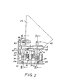
- the manipulator designated as a whole by the number 1, is used to handle parts that are to be moved when opening and closing a manhole opening M of a pressure vessel D, for example a steam generator in a nuclear power plant. It is only the part of the pressure vessel which has the opening give.
- the opening M is closed by a cover V, which is fastened in a known manner with screw bolts and nuts screwed onto them. The bolts can be tightened by means of a device S before the fastening nuts are tightened up to the system.
- screw tensioners are known in various designs.
- the manipulator 1 has a base frame 21, which can be designed to be stationary or movable.
- the underframe 21 carries an attachment 22 which is provided with a guide 17 for a support 16 equipped with wheels 18.
- On the latter there is an arm-shaped holder 9, which is designed at its end for pivotally receiving the screw tensioning device S.
- the latter has on its underside a fork-shaped projection 19 which engages around the end of the holder 9, a pivot pin 20 being inserted through bores in these parts.
- the screw tensioning device S can be adjusted in angle relative to the holder 9, in particular from the working position shown with solid lines, in which its central axis coincides with the central axis A of the opening M, into one with dash-dotted lines indicated horizontal rest position and vice versa. As shown, this angular adjustment can take place together with the cover V or without it.
- a hydraulic piston-cylinder unit 10 is provided as the drive for moving the support 16 in its guide 17, whose piston rod 11 carries a bearing body 12 with a gear 13 freely rotatably mounted therein. On the one hand, this engages in a rack 14, which is also fastened in the attachment 22 approximately in its longitudinal center plane in the region below the piston rod 11, and on the other hand in a rack 15 attached to the underside of the support 16. It is thereby achieved that the distance covered by the support 16 is twice as large as the distance covered by the piston rod 11.
- the underframe 21 has an approximately square base part 3 and a likewise approximately square supporting body 4 which is arranged at a certain distance above it.
- the latter is connected to the base body 3 by four support elements 5, 6, 7, 8 and, in the embodiment shown, can be adjusted in different directions both in height and in its inclination relative to the base body 3.
- the supporting body 4 in the embodiment shown has a downward-facing guide projection 41, starting from its underside in the middle thereof, in particular in the form of a cylindrical pin which is received by a spherical bearing 31 in the base part 3 and extends through it.
- the spherical bearing 31 advantageously contains a spherical head 33 which is held in an angularly movable manner in a multi-part receiving body 32 with a spherically curved inner surface, with a continuous axial bearing arrangement 34 for the guide shoulder 41 of the supporting body 4.
- the bearing arrangement 34 can be a sliding guide, but in particular one with rolling elements equipped longitudinal guide act.
- the four support elements 5 to 8 engage the base part 3 while leaving an angular mobility with respect to the vertical. They are designed as threaded spindles, which can be screwed with their external threads 29 into internal threads 30 of the supporting body 4 and each have a polygon 28 at the upper ends for key engagement.
- the threaded spindles 5 and 6 located on the left side of the underframe 21 in FIG. 1 and 2 are angled in the base part 3 in spherical bearings 35, but axially immovable. The latter is effected in each case by a shoulder 25 on one side and a bushing 27 tightened by means of nut 26 on the other side of the spherical bearing.
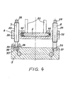
- the one threaded spindle 7 is held axially immovably on the base part 3 by a split retaining ring 39 which overlaps a shoulder 38, while free support is provided for the other threaded spindle 8, as shown in FIG. 4, so that it can also be temporarily removed from it Camp 37 can take off.
- the support body 4 By turning the threaded spindles 5, 6, 7, 8 by means of a key or a ratchet (indicated in FIG. 2 by the number 40), be it individually, or in particular in pairs at the same time, the support body 4 and thus the entire body arranged thereon Set up in any direction in its inclination relative to the base part and also in height be put.
- the device can in any case be quickly and precisely aligned with an opening from which a cover is to be removed or onto which a cover is to be placed, in particular such that the direction of movement of a support 16 or other adjustable part is parallel to the central axis A of the relevant opening M runs.
- the support body 4 is provided with a linear guide 42 which slidably receives a base plate 2 of the attachment 22, so that the latter is adjustable relative to the support body 4.
- An adjusting spindle 44 which is rotatably but axially immovably mounted in an abutment 43 of the supporting body 4 and which engages in a nut part 45 of the attachment 22, is used to generate the movement.
- the base part 3 can, depending on the requirements, be firmly mounted on the floor or can also be made movable. In Fig. 1, both possibilities with bolts 46 and wheels 47 are indicated schematically. In particular, the execution can be made as illustrated in FIG. 2.
- the base part 3 is provided on two sides with two rollers 51 each, which run in C-shaped rails 53. The latter are fastened to the floor or a base plate 50 in the direction desired in the respective application. Two further pairs of rollers 52 on the base part 3 run on the upper inner end faces of the rails 53.
- the number 55 (FIG. 2) denotes a braking or locking device in which a brake shoe 56 held in an angularly movable manner by means of a spindle 57 screwable in the supporting body 4 the top of a rail 53 can be pressed.
- the explained design and arrangement of the attachment 22 and the parts assigned to it, in particular the rack drive for the support 16, is a particularly advantageous embodiment which is preferably taken into account by the invention in connection with the design of the underframe.
- the invention is not limited to this, but also includes other parts and devices for moving a screw tensioning device and / or a cover carried by the underframe according to the invention.
Landscapes
- Engineering & Computer Science (AREA)
- Mechanical Engineering (AREA)
- Manipulator (AREA)
- Bathtub Accessories (AREA)
Applications Claiming Priority (2)
| Application Number | Priority Date | Filing Date | Title |
|---|---|---|---|
| DE8511616U | 1985-04-19 | ||
| DE19858511616 DE8511616U1 (de) | 1985-04-19 | 1985-04-19 | Manipulator für Deckelverschluß-Teile |
Publications (2)
| Publication Number | Publication Date |
|---|---|
| EP0202465A2 true EP0202465A2 (fr) | 1986-11-26 |
| EP0202465A3 EP0202465A3 (fr) | 1989-03-15 |
Family
ID=6780126
Family Applications (1)
| Application Number | Title | Priority Date | Filing Date |
|---|---|---|---|
| EP86105075A Withdrawn EP0202465A3 (fr) | 1985-04-19 | 1986-04-14 | Manipulateur pour éléments de fermeture de couvercle |
Country Status (2)
| Country | Link |
|---|---|
| EP (1) | EP0202465A3 (fr) |
| DE (1) | DE8511616U1 (fr) |
Cited By (1)
| Publication number | Priority date | Publication date | Assignee | Title |
|---|---|---|---|---|
| US9316243B2 (en) | 2010-11-11 | 2016-04-19 | Henrob Limited | Method for forming a joint in a stack of light metal alloy sheets |
Family Cites Families (10)
| Publication number | Priority date | Publication date | Assignee | Title |
|---|---|---|---|---|
| BE511727A (fr) * | ||||
| US2994443A (en) * | 1958-09-15 | 1961-08-01 | Julian E Gordon | Equipment for removing engine turbine rotors while installed in aircraft |
| DE2614654C2 (de) * | 1976-04-05 | 1982-12-09 | Kraftwerk Union AG, 4330 Mülheim | Transport- und Montagegerät für Schraubenspannvorrichtungen |
| BE861168A (fr) * | 1977-11-24 | 1978-03-16 | Hanrez Sa J Atel | Dispositif de manoeuvre d'un couvercle de generateur de vapeur d'une centrale electronucleaire |
| US4224363A (en) * | 1977-12-08 | 1980-09-23 | Westinghouse Electric Corp. | Motor jacking apparatus |
| FR2420828A1 (fr) * | 1978-03-23 | 1979-10-19 | Cockerill | Dispositif pour demonter et remonter des couvercles de trous d'homme sur un appareil sous pression |
| FR2445754A1 (fr) * | 1979-01-08 | 1980-08-01 | Harmand Pierre | Support inclinable pour objet ou piece a usiner |
| DE7916956U1 (de) * | 1979-06-13 | 1979-10-18 | Kloeckner-Werke Ag, 4100 Duisburg | Positioniereinrichtung fuer schraubenspannvorrichtungen zum oeffnen und schliessen von druckbehaeltern |
| FR2544269A1 (fr) * | 1983-04-15 | 1984-10-19 | Malaquin Jean Paul | Chariot, en particulier pour le demontage et la manutention de boites de vitesse et equipement pour travaux de garage comprenant plusieurs chariots montes sur un meme rail |
| US4507841A (en) * | 1984-05-17 | 1985-04-02 | Vista Polymers Inc. | Removal and reinstallation of bottom entering agitator seals |
-
1985
- 1985-04-19 DE DE19858511616 patent/DE8511616U1/de not_active Expired
-
1986
- 1986-04-14 EP EP86105075A patent/EP0202465A3/fr not_active Withdrawn
Cited By (1)
| Publication number | Priority date | Publication date | Assignee | Title |
|---|---|---|---|---|
| US9316243B2 (en) | 2010-11-11 | 2016-04-19 | Henrob Limited | Method for forming a joint in a stack of light metal alloy sheets |
Also Published As
| Publication number | Publication date |
|---|---|
| DE8511616U1 (de) | 1985-06-05 |
| EP0202465A3 (fr) | 1989-03-15 |
Similar Documents
| Publication | Publication Date | Title |
|---|---|---|
| EP0366878A1 (fr) | Table d'opération | |
| DE2225496A1 (de) | Gerät zur Befestigung der Bolzen eines Reaktordruckgefässkopfes am Reaktordruckgefäss | |
| DE2652732C3 (de) | Schieberverschluß | |
| DE2442798A1 (de) | Vorrichtung fuer schraubenverbindungen | |
| DE29806823U1 (de) | Vorrichtung zum Hantieren mindestens eines Spannrahmens, insbesondere für die Montage von Rohkarosserien von Fahrzeugen | |
| DE2550743C2 (de) | Durch eine Gewindespindel gesteuerte Positioniervorrichtung | |
| DE10216258B4 (de) | Triebwerkstand | |
| DE3208705A1 (de) | Vorrichtung zum vorschieben und ausrichten von werkstuecken in einer presse | |
| DE3906616C2 (fr) | ||
| DE10223666A1 (de) | Farbwerksaufbau bei Flexodruckmaschinen | |
| EP0202466B1 (fr) | Manipulateur pour éléments de fermeture de couvercle | |
| EP0202465A2 (fr) | Manipulateur pour éléments de fermeture de couvercle | |
| DE2311174A1 (de) | Vorrichtung zum ausrichten von insbesondere eisenbahnschienen | |
| DE3208209A1 (de) | Vorrichtung zum befestigen eines zylinderstueckes, z.b. eines rohres oder einer welle, zur bearbeitung | |
| CH635273A5 (de) | Vorrichtung zum loesbaren befestigen von werkstuecken an einem arbeitstisch. | |
| DE2700284A1 (de) | Vorrichtung zur befoerderung von insbesondere kleinen gegenstaenden in allen richtungen | |
| DE2216943A1 (de) | Rückstellmechanismus mit veränderlichem Hub, insbesondere für eine Werkzeugmaschine | |
| EP0139781B1 (fr) | Manipulateur | |
| DE1627599A1 (de) | Vorrichtung zum Anbringen und Fuehren eines Wagens auf einem Blech | |
| DE3217521A1 (de) | Vorrichtung fuer den transfer von werkstuecken | |
| EP0509972A2 (fr) | Dispositif de chargement pour tenonneux et machines similaires | |
| DE2719065A1 (de) | Schraubturm zum einschrauben und ausschrauben grosser schraubenbolzen | |
| WO1988004972A1 (fr) | Dispositif permettant le deplacement rectiligne de pieces ou d'objets | |
| DE3238939A1 (de) | Vorrichtung zum herstellen von metallbaendern | |
| DE69001260T2 (de) | Verfahren zur abstuetzung und zur regelung der position eines oberriegels in einer form zum druckgiessen von metallischen platten produkten oder brammen. |
Legal Events
| Date | Code | Title | Description |
|---|---|---|---|
| PUAI | Public reference made under article 153(3) epc to a published international application that has entered the european phase |
Free format text: ORIGINAL CODE: 0009012 |
|
| AK | Designated contracting states |
Kind code of ref document: A2 Designated state(s): DE FR GB IT |
|
| PUAL | Search report despatched |
Free format text: ORIGINAL CODE: 0009013 |
|
| AK | Designated contracting states |
Kind code of ref document: A3 Designated state(s): DE FR GB IT |
|
| STAA | Information on the status of an ep patent application or granted ep patent |
Free format text: STATUS: THE APPLICATION IS DEEMED TO BE WITHDRAWN |
|
| 18D | Application deemed to be withdrawn |
Effective date: 19890916 |
|
| RIN1 | Information on inventor provided before grant (corrected) |
Inventor name: HENSCHENMACHER, HELMUT |