EP0202955A2 - Dyalisierender Elektrofilter mit Elektrode - Google Patents
Dyalisierender Elektrofilter mit Elektrode Download PDFInfo
- Publication number
- EP0202955A2 EP0202955A2 EP86303974A EP86303974A EP0202955A2 EP 0202955 A2 EP0202955 A2 EP 0202955A2 EP 86303974 A EP86303974 A EP 86303974A EP 86303974 A EP86303974 A EP 86303974A EP 0202955 A2 EP0202955 A2 EP 0202955A2
- Authority
- EP
- European Patent Office
- Prior art keywords
- chamber
- filtrate
- membrane
- catholyte
- anolyte
- Prior art date
- Legal status (The legal status is an assumption and is not a legal conclusion. Google has not performed a legal analysis and makes no representation as to the accuracy of the status listed.)
- Withdrawn
Links
Images
Classifications
-
- B—PERFORMING OPERATIONS; TRANSPORTING
- B01—PHYSICAL OR CHEMICAL PROCESSES OR APPARATUS IN GENERAL
- B01D—SEPARATION
- B01D61/00—Processes of separation using semi-permeable membranes, e.g. dialysis, osmosis or ultrafiltration; Apparatus, accessories or auxiliary operations specially adapted therefor
- B01D61/42—Electrodialysis; Electro-osmosis ; Electro-ultrafiltration; Membrane capacitive deionization
- B01D61/56—Electro-osmotic dewatering
-
- B—PERFORMING OPERATIONS; TRANSPORTING
- B01—PHYSICAL OR CHEMICAL PROCESSES OR APPARATUS IN GENERAL
- B01D—SEPARATION
- B01D35/00—Filtering devices having features not specifically covered by groups B01D24/00 - B01D33/00, or for applications not specifically covered by groups B01D24/00 - B01D33/00; Auxiliary devices for filtration; Filter housing constructions
- B01D35/06—Filters making use of electricity or magnetism
-
- B—PERFORMING OPERATIONS; TRANSPORTING
- B01—PHYSICAL OR CHEMICAL PROCESSES OR APPARATUS IN GENERAL
- B01D—SEPARATION
- B01D57/00—Separation, other than separation of solids, not fully covered by a single other group or subclass, e.g. B03C
- B01D57/02—Separation, other than separation of solids, not fully covered by a single other group or subclass, e.g. B03C by electrophoresis
Definitions
- the present invention relates to a process and apparatus for dewatering a suspension of solids in a carrier liquid by means of an electrically augmented vacuum filter (EAVF R . a trademark of Dorr-Oliver, Inc.) including means for depositing solids from the bath of suspended solids onto an anodic structure and means for filtering filtrate from the bath of the suspension of solids at a cathodic structure.
- the cathodic structure comprises a cathode, catholyte, catholyte chamber, and filtrate chamber.
- the catholyte chamber has a membrane wall which is an ion exchange membrane, means for introducing and removing catholyte from this catholyte chamber, and means for removing the filtrate from the filtrate chamber.
- the membrane wall of the catholyte chamber may include either a non ion selective membrane or an anion exchange membrane according to the present invention.
- the double chambered structure may be applied to the anode if it is desired that the anode be used to filter the filtrate from a suspension of solids.
- the liquid-pervious wall of the electrode which is opposite the cake depositing electrode and which allows carrier liquid to be withdrawn therefrom under vacuum has the problem in that the filtrate drawn through it is contaminated with the electrode reaction products. Also, the electrode having a liquid-pervious wall has a reduction in the flux of the filtration so that the amount of filtrate removed during a defined period of time is substantially reduced.
- the filtrate withdrawal rate starts off very high, then drops to some equilibrium value after several days of operation.
- the filtrate rate will then be fairly constant, fluctuating based on variations in the feed composition, conductivity, and machine operating parameters, It is believed that the charged capillaries which are responsible for electro-osmotic pumping of filtrate become poisoned with hydroxide which is generated at the cathode.
- the high conductivity of hydroxide generated at the cathode surface diffuses into the capillaries so that the filtration rate declines. Because of the cathode assembly structure of earlier EAVF devices, where the cathode filter material is placed directly on a perforated electrode screen, it is felt that there are instances where back diffusion of hydroxide exceeds the forward flow of filtrate.
- U.S. Patent No. 4,312, 729 disclodes a cathodic structure comprising a catholyte chamber, perm-selective membrane, and filtrate chamber. Wills attempts to prevent hydroxide generated from the cathodic reaction from passing into the feed slurry by providing a perm-selective membrane between the electrolyte chamber and the filtrate chamber.
- the cation selective membrane according to Wills attempts to prevent contamination of the feed suspension or filter cake with hydroxide and other ions which are deleterious to the suspension of the slurry.
- the perm-selective membrane of Wills are those membranes permeable to cations and substantially impermeable to anions, gases, water, and other liquid.
- the disadvantage of Wills is that the cation exchange membrane results in an extremely dialyzed filtrate, since negative ions are transported out of the filtrate into the bath and are not replenished due to the impermeability of the membranes to anions, resulting in an extremely high voltage drop across the filtrate chamber due to low conductivity and polarization layers. All the electrical current flow is forced by the cation exchange membrane to be carried across the boundary by positive ions. The high voltage drop is not very desirable due to its increased energy consumption.
- the present invention aims to overcome the following disadvantages of the prior art: contamination of electrolyte, reduction in the flow rate of filtrate, dialyzing of the filtrate, and high voltage drop across the filtrate chamber due to low conductivity and polarization layers.
- the present invention provides a system and apparatus for dewatering a suspension of solids in a carrier liquid by means of an EAVF.
- the present invention provides and EAVF system which includes an anodic structure comprising an anode, anolyte. and a membrane for depositing solids from the suspension of solids thereon: and a cathodic structure comprising a cathode, catholyte, catholyte chamber, and filtrate chamber for filtering the filtrate of a bath of the suspension of solids.
- the catholyte chamber according to the present invention, has a membrane wall which is either an anion exchange membrane or a non ion selective membrane.
- a filtrate chamber comprising a filter medium which is both liquid pervious and acts as a positive barrier to solids being filtered.
- the filter medium of the filtrate chamber may be supported by a grid positioned within the filtrate chamber itself.
- the anion exchange membrane is prepared from an anion exchange resin and binder, and the non ion selective membrane is prepared from a mixture comprising an anion exchange resin, a cation exchange resin, and a binder.
- the cathodic structure may be used for depositing solids of a suspension thereon and the anodic structure used for filtering the filtrate of the bath.
- the anodic structure would include an anolyte chamber and a filtrate chamber similar to that discussed when the cathodic structure is used for removing filtrate from the bath.
- the membrane in the anolyte chamber would be selected from the group consisting of an anion exchange membrane, a cation exchange mambrane, and non ion selective membrane.
- a cathodic structure wherein a filtrate chamber is formed between an outer membrane wall of a catholyte chamber and a filter medium, the filter medium being in contact with a suspension of solids to be dewatered.
- the filter medium is liquid pervious to allow filtrate of the suspension of solids to enter the filtrate chamber for removal therefrom, but is impermeable to the solids in the bath.
- the use of a filtrate chamber and catholyte chamber prevents the filtrate from being contaminated and the filtrate from having increased conductivity and pH.
- the catholyte does not have to be continously replenished, resulting in substantial cost savings and a more desiable filtrate is obtained.
- the use of a recirculating electrolyte system also decreases the amount of electrolyte to be replenished.
- the ion exchange membrane of the catholyte structure should not be in contact with the cathode. More specifically, the electrolyte should flow between the cathode and the ion exchange membrane to sweep away the electrode reaction products, e.g. hydroxide. In the case of recycled electrolyte, this allows the acid from the anode to neutralize the base from the cathode. This also assists in preventing hydroxide ions from being transported into the filtrate chamber. If. however, the anion exchange membrane rests on the cathode, local concentrations of hydroxide form adjacent to the membrane, such that the transport across the membrane into the filtrate is predominantly hydroxide ions, which is undesirable. This is because the filtrate will have an increased pH level.
- the electrode reaction products e.g. hydroxide
- the cathodic structure according the present invention be designed to force flow of electrolyte between the electrode and the ion exchange membrane.
- the use of a double chamber cathodic structure wherein the catholyte chamber comprises a cation exchange membrane is disclosed in U.S. Patent No 4,312,792.
- the present invention provides an improvement over that disclosure, in a cathodic structure for dewatering a suspension of solids in a carrier liquid by means of an EAVF system wherein either an anion exchange membrane or a non ion selective membrane is used as the membrane wall of the catholyte chamer.
- the primary object is to avoid a dialyzed filtrate which occurs during use of a cation exchange membrane of the prior art.
- This aspect of the present invention permits the transfer of anions into the filtrate while maintaining a fairly neutral pH and low conductivity. Contrary to what was taught in U.S.
- Patent No 4,312,729 hydroxide ions do not necessarily mass migrate into the filtrate but can be made to remain in the electrolyte of the catholyte chamber.
- the hydroxide generated at the cathode can be recirculated to neutralize the acid produced in the electrolyte of the anodic structure.
- the cathodic structure according to present invention therefore allows anions, but limits hydroxide ions, to migrate into the filtrate, thereby preventing dialyzing of the filtrate and high voltage drop across the filtrate chamber due to low conductivity and polarization layers.
- the cathodic structure according to the present invention can be used in an EAVF system for dewatering the suspension of solids in a carrier liquid as shown in U.S. Patent No5. 4,168,222 No. 4,207,158, wherein at least a pair of self-contained mutually opposed electrode structures are positioned in a tank containing a suspension of solids, one electrode being a cathodic electrode structure and the other an anodic electrode structure having between them a controllable electrical field, while submerged in a suspension.
- the membrane of the anode being at least one selected from the group consisting of anion exchange membranes, cation exchange membranes, or non ion selective membranes.
- the cathodic structure having a filtrate chamber and a catholyte chamber removes filtrate from the bath without contaminating the electrolyte.
- the catholyte and anolyte can be recirculated in order to reduce the amount of electrolyte solutions added to the electrode structures during operation.
- Another embodiment of the present invention positions an anodic structure between a pair of cathodic structures for deposition of the solids of the suspension on both sides of the anodic structure.
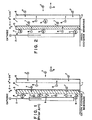
- Fig. 1 is a graphic representation of a cation exchange membrane 3 wall in a cathodic structure 1 according to the prior art.
- the cathodic structure 1 of Fig. 1 includes a cathode 2 which is electrically connected to a negative terminal, a cation exchange membrane 3 forming a catholyte chamber 4, and a liquid pervious filter medium 5 which forms a filtrate chamber 6.
- Filter chamber 6 permits free flow of both cations and anions, 7 and 8, respectively, as well as the filtrate from a bath,
- the cation exchange membrane 3 permits cations 7 contained within the filtrate chamber 6 to pass therethrough into the catholyte chamber 4 to react at cathode 2.
- Cation exchange membrane 3 does not, however, permit passage of either anions 8 or hydroxide ions 9.
- anions 8 in filtrate chamber 6 are attracted towards an opposing anode the filtrate is dialyzed.
- the electrical current flow is forced by the cation exchange membrane 3 to be carried across by anions only. This results in an extremely dialyzed filtrate, since negative ion have to be transported out of the filtrate to the bath to maintain charge neutrality.
- the net affect is an extremely high voltage drop across the filtrate chamber due to low conductivity and polarization layers, the economics of which are undesirable.
- Fig. 2 graphically describes a cathodic structure according to the present invention, wherein the membrane used to define the catholyte chamber 4 is anion exchange membrane 10.
- a non ion selective membrane may also be used in place of the anion exchange resin 10 according to the present invention.
- anions 8 in the catholyte chamber 4 may pass through the anion exchange membrane 10 into the filtrate chamber 6 due to membrane permeability and attraction to the electrical pull of the anode.
- the cations 7 in filtrate chamber 6 are unable to pass through the membrane 10 and remain in the filtrate chamber 6.
- hydroxide ions 9 are anions and should be able to pass through the anion exchange membrane 10, it has been observed by the present inventor that hydroxide ions tend to remain in the catholyte and do not pass between anion exchange membrane 10 into the filtrate chamber 6. It is this phenomenon which permits the conductivity of the filtrate in the filtrate chamber 6 to remain quite low and the pH of the filtrate to remain near neutral. Thus, it appears that most of the transport through the anion exchange membrane 10 is by anions 8 other than hydroxide ions 9. The hydroxide ions in the catholyte are recirculated to neutralize the acid of the anolyte.
- the cathode 2 not contact the anion exchange membrane 10, in order to avoid local concentrations of hydroxide ion 9 from forming adjacent to the membrane 10 and transporting across the membrane 10 into the filtrate chamber 6. which would increase both the pH and conductivity of the filtrate. Also, the catholyte would be depleted of hydroxide ions, resulting in its pH dropping to an undesirable level.
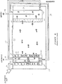
- Fig. 3 provides a cathodic structure according to the present invention comprising a cathode 12, filtrate chamber 13, and catholyte chamber 14.
- Filtrate chamber 13 comprises a liquid pervious filter medium 16 and, optionally, a support grid 17.
- the liquid pervious filter medium 16 is permeable to both anions and cations but impermeable to solids of the suspension.
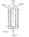
- Fig. 4 decribes recycling of electrolyte from cathode to anode and from anode to cathode, which preserves electrolyte and avoids continuous replenishing of the electrolyte therein.
- Fig. 4 provides a cathodic structure 22 and an anodic structure 23 being submerged in a bath 24 of a suspension of solids in a carrier liquid contained in tank 25.
- the anodic structure comprising an anode 26 and membrane 27 containing anolyte 38 therein.
- Membrane 27 is liquid impervious and may be selected from the group consisting of anion exchange membranes, cation exchange membranes, non ion selective membrane, and any other liquid impervious membrane. Solids of the solution form a cake 28 on membrane 27 which may be removed by doctoring or blow back when the anodic structure is extracted from the bath 24.
- Cathodic structure 22 includes a fillrate chamber 29 and a catholyte chamber 30.
- the filtrate chamber 29 is formed between a liquid pervious filter medium 31, the outer surface of which is in contact with bath 24, and membrane wall 32 of the catholyte chamber.
- a support grid 33 may be placed within the filtrate chamber 29 to support the liquid pervious filter medium 31.
- the catholyte chamber 30 is formed by membrane 32 which is not in contact with cathode 34 and contains catholyte 35 therein.
- the filtrate contained within the filtrate chamber 29 is removed from cathodic structure 22 via conduit 36 by conventional vacuum means.
- the filtrate has a low conductivity and a relatively neutral pH.
- the catholyte 35 is recirculated via conduit 37 to the anolyte 38 of anodic structure 23 in order to neutralize the acid produced by the reaction of the anolyte 38 at the anode 26. It is withdrawn from anodic structure 23 via conduit 39 and recirculated into the catholyte chamber 30 of the cathodic structure 22. It should be noted that recirculating of the electrolyte between the cathode and the anode is not 100% efficient. The electrolyte still requires replenishing from time to time. It may also be desirable to recirculate the catholyte by itself and the anolyte by itself for polarization control within the catholyte and anolyte chambers, respectively.
- a cathodic structure according to the present invention was prepared having a filtrate chamber wall of a liquid impervious microporous membrane made of any conventional filter material which is a positive barrier to the solids being filtered and which would not limit the flux due to hydraulic resistance.
- Dynel TM cloth was used as the filter medium but the pore size in the Dynel was larger than the particles it was holding back, which permitted particles to enter the filtrate chamber, contaminating the filtrate.
- the filtrate chamber must use a filter medium which is a positive barrier to the solids being filtered. e.g. a 0.5 ⁇ AMF nylon membrane cast on a polyester support.
- the membrane wall of the catholyte chamber can be either an anionic ion exchange membrane or a non ion selective membrane.
- One preferred membrane is Dynel filter cloth impregnated with an anion exchange resin and secured thereto by means of organic binder. This membrane is both liquid and cation impervious, but anion pervious.
- a non ion selective membrane could be formed by impregnating Dynel filter cloth with a mixture of cation exchange resin and anion exchange resin in a binder.
- the aforementioned cathodic structure was placed in a bath of a suspension of solids in a carrier liquid opposite an anodic structure and demonstrated the results shown in Table I below
- the dewatering surface of the single chambered cathodic structure was a Dynel cloth, while the filtrate chamber wall of the cathodic structure of the present invention was 0.45 ⁇ nylon with a polyester support. Moreover, the membrane of the catholyte chamber was an anion exchange membrane.
- Table II compares the data and results obtained during each test run.
- the filtrate of the present invention was not cloudy such as that obtained during dewatering with the standard single chambered cathodic structure. Also the filtrate rate of the standard cathodic structure was substantially reduced due to back flow of hydroxide ions which reduced the electroosmotic pumping of the pores therein, whereas the filtrate rate of the cathodic structure of the present invention remained relatively high.
- the cake depositing (product) rate of the present invention was substantially higher than the prior art device, while the operating cost of the EAVF device per dry ton of product was approximately four times higher for the prior art cathodic structure than for the cathodic structure of the present invention.
Landscapes
- Engineering & Computer Science (AREA)
- Chemical & Material Sciences (AREA)
- Water Supply & Treatment (AREA)
- Chemical Kinetics & Catalysis (AREA)
- Health & Medical Sciences (AREA)
- Life Sciences & Earth Sciences (AREA)
- Electrochemistry (AREA)
- Environmental & Geological Engineering (AREA)
- Molecular Biology (AREA)
- Urology & Nephrology (AREA)
- Separation Using Semi-Permeable Membranes (AREA)
Applications Claiming Priority (2)
| Application Number | Priority Date | Filing Date | Title |
|---|---|---|---|
| US738198 | 1985-05-24 | ||
| US06/738,198 US4668361A (en) | 1985-05-24 | 1985-05-24 | Dialyzing electrofilter with improved electrode |
Publications (2)
| Publication Number | Publication Date |
|---|---|
| EP0202955A2 true EP0202955A2 (de) | 1986-11-26 |
| EP0202955A3 EP0202955A3 (de) | 1987-09-09 |
Family
ID=24966973
Family Applications (1)
| Application Number | Title | Priority Date | Filing Date |
|---|---|---|---|
| EP86303974A Withdrawn EP0202955A3 (de) | 1985-05-24 | 1986-05-23 | Dyalisierender Elektrofilter mit Elektrode |
Country Status (5)
| Country | Link |
|---|---|
| US (1) | US4668361A (de) |
| EP (1) | EP0202955A3 (de) |
| JP (1) | JPS6219203A (de) |
| KR (1) | KR860008789A (de) |
| AU (1) | AU5769486A (de) |
Cited By (1)
| Publication number | Priority date | Publication date | Assignee | Title |
|---|---|---|---|---|
| EP0241308A1 (de) * | 1986-04-11 | 1987-10-14 | Dorr-Oliver Incorporated | Entfernungsverfahren von ausgewählten Ionen aus Kuchen, abgesetzt auf einem elektrisch verschnellten Vakuumfiltriergerät |
Families Citing this family (5)
| Publication number | Priority date | Publication date | Assignee | Title |
|---|---|---|---|---|
| JP2562973B2 (ja) * | 1988-03-07 | 1996-12-11 | 理化学研究所 | 多孔質高分子膜及び高分子複合膜の製造方法 |
| US5238636A (en) * | 1988-03-07 | 1993-08-24 | Rikagaku Kenkyusho | Processes for producing porous polymer films and composite films |
| US5047126A (en) * | 1989-04-19 | 1991-09-10 | Bernard Greenberg | Method for recovering metal from waste stream |
| ATE110588T1 (de) * | 1990-06-20 | 1994-09-15 | Heinz Zimmermann | Vorrichtung und verfahren zum aufbereiten von wasser. |
| US5364527A (en) * | 1990-06-20 | 1994-11-15 | Heinz Zimmermann | Apparatus and process for treating water |
Family Cites Families (10)
| Publication number | Priority date | Publication date | Assignee | Title |
|---|---|---|---|---|
| US3577331A (en) * | 1967-06-08 | 1971-05-04 | Interior And Southern Research | Apparatus and process for effecting changes in solution concentrations |
| FR2131859B1 (de) * | 1971-03-30 | 1974-03-08 | Rhone Poulenc Sa | |
| US4048038A (en) * | 1974-07-08 | 1977-09-13 | J. M. Huber Corporation | Electroflocculation cell |
| BR7607267A (pt) * | 1976-05-24 | 1977-09-13 | Huber Corp J M | Celula de eletrofloculacao e processo para separacao eletrocinetica de particulas de argila |
| US4207158A (en) * | 1976-06-17 | 1980-06-10 | Dorr-Oliver Incorporated | Electrically augmented vacuum filtration |
| US4244804A (en) * | 1979-01-15 | 1981-01-13 | Innova, Inc. | Slime and sludge dewatering |
| US4331525A (en) * | 1979-11-13 | 1982-05-25 | Diamond Shamrock Corporation | Electrolytic-ultrafiltration apparatus and process for recovering solids from a liquid medium |
| US4312729A (en) * | 1980-10-31 | 1982-01-26 | Engelhard Minerals & Chemicals Corporation | Dewatering with electrically augmented vacuum filter |
| EP0084582B1 (de) * | 1982-01-26 | 1986-08-13 | Engelhard Corporation | Entwässerung mit einem elektrisch beschleunigten Vakuumfilter |
| FR2538551B1 (fr) * | 1982-12-27 | 1988-11-10 | Asahi Chemical Ind | Procede et installation de deshydratation d'une substance contenant de l'eau par electro-osmose |
-
1985
- 1985-05-24 US US06/738,198 patent/US4668361A/en not_active Expired - Fee Related
-
1986
- 1986-05-21 JP JP61118361A patent/JPS6219203A/ja active Pending
- 1986-05-22 AU AU57694/86A patent/AU5769486A/en not_active Abandoned
- 1986-05-23 EP EP86303974A patent/EP0202955A3/de not_active Withdrawn
- 1986-05-24 KR KR1019860004080A patent/KR860008789A/ko not_active Ceased
Cited By (1)
| Publication number | Priority date | Publication date | Assignee | Title |
|---|---|---|---|---|
| EP0241308A1 (de) * | 1986-04-11 | 1987-10-14 | Dorr-Oliver Incorporated | Entfernungsverfahren von ausgewählten Ionen aus Kuchen, abgesetzt auf einem elektrisch verschnellten Vakuumfiltriergerät |
Also Published As
| Publication number | Publication date |
|---|---|
| AU5769486A (en) | 1986-11-27 |
| US4668361A (en) | 1987-05-26 |
| JPS6219203A (ja) | 1987-01-28 |
| KR860008789A (ko) | 1986-12-18 |
| EP0202955A3 (de) | 1987-09-09 |
Similar Documents
| Publication | Publication Date | Title |
|---|---|---|
| US4604174A (en) | High flow electrofiltration | |
| US4124458A (en) | Mass-transfer membrane and processes using same | |
| DE2437273C2 (de) | ||
| US4048038A (en) | Electroflocculation cell | |
| DE69817077T2 (de) | Behandlungsverfahren und Vorrichtung, die eine chemische Reaktion verwenden | |
| US4758319A (en) | Dialyzing crossflow electrofilter with improved electrode | |
| EP0187549A2 (de) | Elektrofilter mit Elektrodenanordnung | |
| US3980547A (en) | Electrokinetic cell | |
| US4132626A (en) | Electroflocculation cell | |
| US5171409A (en) | Continuous process of separating electrically charged solid, pulverulent particles by electrophoresis and electroosmosis | |
| US3827961A (en) | Method for purifying ionically conducting solutions | |
| DE3141949A1 (de) | Verfahren zur kontinuierlichen regeneration von eisentrichloridloesungen | |
| US4468306A (en) | Biodic electrofiltration | |
| US4668361A (en) | Dialyzing electrofilter with improved electrode | |
| US3945900A (en) | Electro ultrafiltration process and apparatus | |
| US3496077A (en) | Electrolyzing of salt solutions | |
| US3309301A (en) | Method for producing a deionized liquid product by electrodialysis | |
| US4619747A (en) | Electrofilter process using recirculating electrolyte | |
| US4615786A (en) | Non ion selective membrane in an EAVF system | |
| US3347761A (en) | Electropurification of salt solutions | |
| AU601447B2 (en) | A continuous process of separating electrically charged solid, pulverulent particle by electrophoresis and electroosmosis | |
| US4689134A (en) | Non ion selective membrane in an EAVF system | |
| DE2140310A1 (de) | Heterogene semipermeable Kunststoff membran zur Trennung von Flussigkeits oder Gasgemischen | |
| US4693802A (en) | Electrically augmented vacuum filtration apparatus for producing a dialyzed cake product | |
| EP0202934A2 (de) | Verfahren und Vorrichtung zur Elektrofiltrierung |
Legal Events
| Date | Code | Title | Description |
|---|---|---|---|
| PUAI | Public reference made under article 153(3) epc to a published international application that has entered the european phase |
Free format text: ORIGINAL CODE: 0009012 |
|
| AK | Designated contracting states |
Kind code of ref document: A2 Designated state(s): AT BE CH DE FR GB IT LI LU NL SE |
|
| PUAL | Search report despatched |
Free format text: ORIGINAL CODE: 0009013 |
|
| AK | Designated contracting states |
Kind code of ref document: A3 Designated state(s): AT BE CH DE FR GB IT LI LU NL SE |
|
| 17P | Request for examination filed |
Effective date: 19880302 |
|
| 17Q | First examination report despatched |
Effective date: 19890619 |
|
| STAA | Information on the status of an ep patent application or granted ep patent |
Free format text: STATUS: THE APPLICATION IS DEEMED TO BE WITHDRAWN |
|
| 18D | Application deemed to be withdrawn |
Effective date: 19891201 |
|
| RIN1 | Information on inventor provided before grant (corrected) |
Inventor name: KLINKOWSKI, PETER R. |