EP0202993A1 - Scheibenbremsenfeder - Google Patents
Scheibenbremsenfeder Download PDFInfo
- Publication number
- EP0202993A1 EP0202993A1 EP86400974A EP86400974A EP0202993A1 EP 0202993 A1 EP0202993 A1 EP 0202993A1 EP 86400974 A EP86400974 A EP 86400974A EP 86400974 A EP86400974 A EP 86400974A EP 0202993 A1 EP0202993 A1 EP 0202993A1
- Authority
- EP
- European Patent Office
- Prior art keywords
- spring
- disc brake
- stirrup
- disc
- main
- Prior art date
- Legal status (The legal status is an assumption and is not a legal conclusion. Google has not performed a legal analysis and makes no representation as to the accuracy of the status listed.)
- Granted
Links
Images


Classifications
-
- F—MECHANICAL ENGINEERING; LIGHTING; HEATING; WEAPONS; BLASTING
- F16—ENGINEERING ELEMENTS AND UNITS; GENERAL MEASURES FOR PRODUCING AND MAINTAINING EFFECTIVE FUNCTIONING OF MACHINES OR INSTALLATIONS; THERMAL INSULATION IN GENERAL
- F16D—COUPLINGS FOR TRANSMITTING ROTATION; CLUTCHES; BRAKES
- F16D65/00—Parts or details
- F16D65/02—Braking members; Mounting thereof
-
- F—MECHANICAL ENGINEERING; LIGHTING; HEATING; WEAPONS; BLASTING
- F16—ENGINEERING ELEMENTS AND UNITS; GENERAL MEASURES FOR PRODUCING AND MAINTAINING EFFECTIVE FUNCTIONING OF MACHINES OR INSTALLATIONS; THERMAL INSULATION IN GENERAL
- F16D—COUPLINGS FOR TRANSMITTING ROTATION; CLUTCHES; BRAKES
- F16D65/00—Parts or details
- F16D65/02—Braking members; Mounting thereof
- F16D65/04—Bands, shoes or pads; Pivots or supporting members therefor
- F16D65/092—Bands, shoes or pads; Pivots or supporting members therefor for axially-engaging brakes, e.g. disc brakes
- F16D65/095—Pivots or supporting members therefor
- F16D65/097—Resilient means interposed between pads and supporting members or other brake parts
- F16D65/0973—Resilient means interposed between pads and supporting members or other brake parts not subjected to brake forces
- F16D65/0974—Resilient means interposed between pads and supporting members or other brake parts not subjected to brake forces acting on or in the vicinity of the pad rim in a direction substantially transverse to the brake disc axis
- F16D65/0977—Springs made from sheet metal
-
- F—MECHANICAL ENGINEERING; LIGHTING; HEATING; WEAPONS; BLASTING
- F16—ENGINEERING ELEMENTS AND UNITS; GENERAL MEASURES FOR PRODUCING AND MAINTAINING EFFECTIVE FUNCTIONING OF MACHINES OR INSTALLATIONS; THERMAL INSULATION IN GENERAL
- F16D—COUPLINGS FOR TRANSMITTING ROTATION; CLUTCHES; BRAKES
- F16D55/00—Brakes with substantially-radial braking surfaces pressed together in axial direction, e.g. disc brakes
- F16D55/02—Brakes with substantially-radial braking surfaces pressed together in axial direction, e.g. disc brakes with axially-movable discs or pads pressed against axially-located rotating members
- F16D55/22—Brakes with substantially-radial braking surfaces pressed together in axial direction, e.g. disc brakes with axially-movable discs or pads pressed against axially-located rotating members by clamping an axially-located rotating disc between movable braking members, e.g. movable brake discs or brake pads
- F16D55/224—Brakes with substantially-radial braking surfaces pressed together in axial direction, e.g. disc brakes with axially-movable discs or pads pressed against axially-located rotating members by clamping an axially-located rotating disc between movable braking members, e.g. movable brake discs or brake pads with a common actuating member for the braking members
- F16D55/225—Brakes with substantially-radial braking surfaces pressed together in axial direction, e.g. disc brakes with axially-movable discs or pads pressed against axially-located rotating members by clamping an axially-located rotating disc between movable braking members, e.g. movable brake discs or brake pads with a common actuating member for the braking members the braking members being brake pads
- F16D55/226—Brakes with substantially-radial braking surfaces pressed together in axial direction, e.g. disc brakes with axially-movable discs or pads pressed against axially-located rotating members by clamping an axially-located rotating disc between movable braking members, e.g. movable brake discs or brake pads with a common actuating member for the braking members the braking members being brake pads in which the common actuating member is moved axially, e.g. floating caliper disc brakes
- F16D55/2265—Brakes with substantially-radial braking surfaces pressed together in axial direction, e.g. disc brakes with axially-movable discs or pads pressed against axially-located rotating members by clamping an axially-located rotating disc between movable braking members, e.g. movable brake discs or brake pads with a common actuating member for the braking members the braking members being brake pads in which the common actuating member is moved axially, e.g. floating caliper disc brakes the axial movement being guided by one or more pins engaging bores in the brake support or the brake housing
-
- F—MECHANICAL ENGINEERING; LIGHTING; HEATING; WEAPONS; BLASTING
- F16—ENGINEERING ELEMENTS AND UNITS; GENERAL MEASURES FOR PRODUCING AND MAINTAINING EFFECTIVE FUNCTIONING OF MACHINES OR INSTALLATIONS; THERMAL INSULATION IN GENERAL
- F16D—COUPLINGS FOR TRANSMITTING ROTATION; CLUTCHES; BRAKES
- F16D55/00—Brakes with substantially-radial braking surfaces pressed together in axial direction, e.g. disc brakes
- F16D2055/0004—Parts or details of disc brakes
- F16D2055/0041—Resilient elements interposed directly between the actuating member and the brake support, e.g. anti-rattle springs
Definitions
- the subject of the invention is a spring for a disc brake with a sliding caliper and a disc brake equipped with such a spring.
- the invention relates more particularly to a multi-function spring intended to equip a disc brake whose caliper slides with respect to a fixed support by means of at least two complementary axial sliding surfaces formed on the caliper and on the support. fixed and which are kept in contact by elastic means.
- disc brakes are known, the caliper of which is slidably mounted relative to the fixed support by means of an axial baluster received in sliding in a corresponding bore and by means of two surfaces. sliding formed vis-à-vis on the bracket and on the fixed support.
- Such a brake is described and represented in patent GB-A-1,532,572.
- it is necessary to provide elastic means for keeping said surfaces in contact as well as anti-noise springs intended to press the organs of friction in support in the opening provided in the fixed support to receive them.
- Document EP -A -0 030 502 proposes using a single spring disposed between the caliper and the friction members ensuring the dual function of keeping said sliding surfaces in contact and of an anti-noise spring for the friction members.
- disc brakes whose caliper is slidably mounted on the fixed support by means of two pairs of complementary sliding surfaces formed respectively on the caliper and on the fixed support, said pairs of sliding surfaces being kept in contact. by means of two springs arranged on either side of the median axial plane of the brake.
- Such a brake is described and shown in document FR -A -2 408 766.
- the technical problem of the present invention is to propose the arrangement of disc brakes with a spring ensuring the functions of anti-noise spring and of holding in preferential lateral position of the friction members, of simplified structure, compact and robust, not very sensitive. tolerance problems, and ensuring improved elastic action on the friction members, elastically ensuring contact between two complementary surfaces of axial sliding.
- a spring for a disc brake of the type comprising a caliper mounted slidingly parallel to the axis of a rotating disc, on a fixed support by means of at least two axial sliding surfaces formed. on the stirrup and on the fixed support and held elastically in contact, and two friction members received in anchoring and in axial sliding in an opening of said fixed support to come into friction engagement with the opposite faces of said disc, during the actuation of a brake motor, said spring being resiliently mounted in an opening formed in the arch of the caliper and exerting on the support plates of said friction members, a radial force directed substantially along a radius of the disc, and in the direction of the axis of the latter and a tangential force perpendicular to said radial force to urge each of the friction members tangentially to the circumference of said disc to ensure the maintenance ien of these in a preferred lateral position, characterized in that it consists of a folded metal blade com-
- said spring having the general shape of a "trident", the extreme branches of which are constituted by said main arms, the latter being capable of cooperating on the one hand, by their free ends with a substantially flat surface formed on the stirrup and extending parallel to the axis of the disc and on the other hand, by central portions with bearing surfaces formed on each of the plates support, said central arm having at its free end a Z-shaped fold capable of cooperating with two surfaces of the stirrup forming an angle a less than an angle ⁇ formed by two consecutive parts of the Z-shaped fold, said main fold comprising a tab extending substantially parallel to and away from said three arms and capable of cooperating radially with another surface formed on said stirrup, said central portions exerting thus on the support plates an elastic force composed of said radial force and said tangential force.
- the elastic action of the spring results essentially from the relative flexions of the three arms connected by the main fold, under the effect of the cooperation of these arms with the surfaces of the stirrup and of the support plates placed near them. each other.
- the tab carried by the main fold keeps the two axial sliding surfaces in contact and positions the spring relative to the caliper.
- the distance between the main fold and the Z-shaped fold of the central arm is such that the spring cannot escape from the opening formed in the arch of the stirrup when this spring does not act not on the friction elements.
- the spring can be held elastically in the opening of the caliper, without risk of loss or deformation during disassembly, for example, when replacing the friction elements.
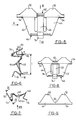
- the disc brake shown in Figures 1 to 3 is of the type comprising a caliper 10, slidably mounted on a fixed support 12, by means of an axial column 14.
- the sliding of the caliper 10 relative to the fixed support 12 is also provided by means of axial sliding surfaces 16 and 18, formed respectively on the caliper 10 and on a spring 20 integral with the fixed support 12.
- the disc brake further comprises two friction members 22 and 24 provided respectively with support plates 26 and 28, capable of coming into friction engagement with a rotating disc 30, upon actuation of a hydraulic brake motor 32.
- the friction members 22 and 24 are received in anchoring and sliding in an opening 34 formed in the fixed support 12.
- the two friction members 22 and 24 have ends 36 and 38 having a circular profile cooperating with circular profiles complementary to the opening 34.
- the disc brake shown in Figures 1 to 3 is provided with a spring 40 made according to the present invention.
- the spring 40 consists of a folded metal blade which comprises two main arms 42 and 44, connected together by a main fold 46, and connected to a arms central 48, still by means of the main fold 46.
- the spring has the general shape of a "trident", the end branches of which are constituted by the main arms 42 and 44, and the central branch by the central arm 48.
- Each of the main arms has a free end 50 capable of cooperating with a substantially flat surface 52, as shown in FIG.
- each of the arms 42 and 44 has a central portion 54 in the form of a gutter, capable of cooperating with bearing surfaces 56 formed on each of the support plates 26 and 28, as shown in Figure 4.
- the bearing surfaces 56 are constituted by a bearing angle formed on a lug 58, disposed at the upper part of the support plates 26 and 28, and by the upper face 60 of these support plates.
- the free end 62 of the central arm 48 has a Z-shaped fold whose hollow closest to the end forms an angle / 3 as shown in FIG.
- the spring 40 is housed in an opening 68, formed in the arch of the stirrup 10 and having two circumferentially spaced edges 70 and 72, the surfaces 52, 64 and 66 being located near the first edge 72.
- the central fold 46 has a tab 74 which extends substantially parallel to the three arms 42, 44 and 48 away from them, and capable of cooperating radially with another surface 76, formed on the stirrup 10, near the second edge 68.
- the main arms 42 and 44 have a section which increases progressively from the free end 50 to the central portion 54, then the section decreases from the central portion 54 to main fold 46.
- FIG. 6 it can be seen that the outer surface 78 of the main fold 46 is distant by a length 1 from the outer surface 81 of the Z-shaped fold of the central arm 48.
- FIG. 4 defines the minimum distance between the circumferentially spaced edges 72 and 70 of the opening 68.
- the length 1 on the spring 40 when the latter does not stress the friction elements, is greater than the length d, so that said spring remains trapped in the opening 68 formed in the stirrup 10.
- the main fold 46 must not be in contact with the stirrup r 10.
- FIG 4 there is shown the different elastic actions generated or undergone by the spring 40. It can be seen in particular that the tangential forces which stress the friction members tangentially to the circumference of the disc, are generated by a relative circumferential bending of the arms main 42 and 44, relative to the central arm 48. These are the forces F5 on the central arm 48 and F'5 exerted by the main arms on the bearing surfaces 56 of the friction elements. The values of F5 and F'5 being of course equal.
- the radial action on the friction elements is designated by F1 and this is composed of the reactions to the forces F2, force of the end 50 on the surface 52, increased by the force F4, reaction of the central arm 48 on the surfaces 64 and 66, and increased by the result of the two opposite but not equal forces F3 and F'4.
- the forces generated are essentially defined by the geometry of the spring, the manufacturing tolerances of the stirrup intervening only very little, the tab 74 being free to move circumferentially relative to the edge 70 of the opening 68.
- the angle a previously defined is smaller than the angle e formed by the Z end of the central arm 48, so as to allow this central arm 48 to follow the movements imposed by the central portions 54 at across the main fold 46.
- FIGS 7 to 9 show a spring variant according to Figures 4 to 6 we see that the central portions 54 are connected together at right angles to the Z-fold of the central arm 48 by means of a connecting portion 82 formed during cutting of the central arm 48 at by means of an opening 84, the latter being such that before folding of the arms 42, 44 and 48, the unfolded length of the central arm 48 is shorter than the corresponding length of the opening 84. Thanks to this variant the rigidity of the portions central 54 is increased and these are better maintained parallel to the axis of the disc 30.
Landscapes
- Engineering & Computer Science (AREA)
- General Engineering & Computer Science (AREA)
- Mechanical Engineering (AREA)
- Braking Arrangements (AREA)
Applications Claiming Priority (2)
| Application Number | Priority Date | Filing Date | Title |
|---|---|---|---|
| FR8507709 | 1985-05-22 | ||
| FR8507709A FR2582366B1 (fr) | 1985-05-22 | 1985-05-22 | Ressort pour frein a disque et frein a disque equipe d'un tel ressort |
Publications (2)
| Publication Number | Publication Date |
|---|---|
| EP0202993A1 true EP0202993A1 (de) | 1986-11-26 |
| EP0202993B1 EP0202993B1 (de) | 1990-01-03 |
Family
ID=9319479
Family Applications (1)
| Application Number | Title | Priority Date | Filing Date |
|---|---|---|---|
| EP86400974A Expired - Lifetime EP0202993B1 (de) | 1985-05-22 | 1986-05-06 | Scheibenbremsenfeder |
Country Status (9)
| Country | Link |
|---|---|
| US (1) | US4699254A (de) |
| EP (1) | EP0202993B1 (de) |
| JP (1) | JPH076562B2 (de) |
| KR (1) | KR940003909B1 (de) |
| DE (1) | DE3668043D1 (de) |
| ES (1) | ES296703Y (de) |
| FR (1) | FR2582366B1 (de) |
| TR (1) | TR27102A (de) |
| YU (1) | YU46995B (de) |
Cited By (3)
| Publication number | Priority date | Publication date | Assignee | Title |
|---|---|---|---|---|
| FR2612586A1 (fr) * | 1987-03-21 | 1988-09-23 | Teves Gmbh Alfred | Frein a disque comportant un ressort de garnitures de frein |
| GB2231108A (en) * | 1989-03-29 | 1990-11-07 | Perrot Bremse Gmbh Deutsche | A leaf spring for holding down a brake lining carrier of a disc brake |
| DE4303961C2 (de) * | 1993-02-10 | 2002-12-05 | Perrot Bremse Gmbh Deutsche | Federanordnung zum Niederhalten der Bremsbeläge in einer Scheibenbremse |
Families Citing this family (20)
| Publication number | Priority date | Publication date | Assignee | Title |
|---|---|---|---|---|
| JPH0774653B2 (ja) * | 1987-04-20 | 1995-08-09 | トキコ株式会社 | デイスクブレ−キ |
| FR2635842B1 (fr) * | 1988-08-29 | 1990-10-19 | Bendix France | Ressort pour frein a disque et frein a disque le comportant |
| DE8906980U1 (de) * | 1989-06-07 | 1990-10-04 | Lucas Industries P.L.C., Birmingham, West Midlands | Teilbelag-Scheibenbremse mit Niederhaltefeder |
| US4969540A (en) * | 1989-09-28 | 1990-11-13 | Allied-Signal Inc. | Center loop anti-rattle spring |
| JPH05280563A (ja) * | 1992-03-31 | 1993-10-26 | Aisin Seiki Co Ltd | ディスクブレーキ |
| US5358079A (en) * | 1993-09-21 | 1994-10-25 | Alliedsignal Inc. | Disc brake with friction pad backing plate biasing spring |
| JPH0874898A (ja) * | 1994-06-29 | 1996-03-19 | Aisin Seiki Co Ltd | ディスクブレーキ用パッドクリップ |
| GB9625862D0 (en) | 1996-12-12 | 1997-01-29 | T & N Technology Ltd | Disc brake |
| GB2340564A (en) | 1998-08-15 | 2000-02-23 | T & N Technology Ltd | Disc brake |
| GB2340563A (en) | 1998-08-15 | 2000-02-23 | T & N Technology Ltd | Disc brake |
| GB2340561A (en) | 1998-08-15 | 2000-02-23 | T & N Technology Ltd | Disc brake |
| GB2361973A (en) | 2000-05-05 | 2001-11-07 | Federal Mogul Brake Syst Ltd | Method and apparatus for mounting a disc brake |
| GB0018154D0 (en) * | 2000-07-25 | 2000-09-13 | Federal Mogul Brake Systems Li | Apparatus and method for controlling a braking system |
| DE102007022905A1 (de) * | 2006-05-24 | 2008-02-21 | Continental Teves Ag & Co. Ohg | Scheibenbremse |
| FR2938873B1 (fr) * | 2008-11-21 | 2014-06-27 | Turbomeca | Organe de positionnement pour segment d'anneau |
| US10443417B2 (en) * | 2015-09-18 | 2019-10-15 | General Electric Company | Ceramic matrix composite ring shroud retention methods-finger seals with stepped shroud interface |
| ITUB20159203A1 (it) | 2015-12-23 | 2017-06-23 | Freni Brembo Spa | Assieme di pastiglia per pinza freno |
| JP6693375B2 (ja) * | 2016-09-30 | 2020-05-13 | 株式会社アドヴィックス | キャリパアセンブリ |
| JP6871829B2 (ja) * | 2017-09-06 | 2021-05-12 | 曙ブレーキ工業株式会社 | 対向ピストン型ディスクブレーキ用キャリパ |
| FR3097923B1 (fr) * | 2019-06-26 | 2022-07-29 | Foundation Brakes France | « Frein à disque comportant au moins un ressort de rappel élastique d'un patin de freinage, ressort de rappel élastique, kit de remplacement et procédé de montage » |
Citations (9)
| Publication number | Priority date | Publication date | Assignee | Title |
|---|---|---|---|---|
| DE1927459A1 (de) * | 1968-05-31 | 1970-05-27 | Girling Ltd | Teilbelagscheibenbremse |
| DE2345733A1 (de) * | 1973-09-11 | 1975-03-20 | Bendix Gmbh | Teilbelagscheibenbremse |
| DE2514383A1 (de) * | 1974-04-02 | 1975-11-20 | Girling Ltd | Fahrzeugscheibenbremse |
| GB1532572A (en) * | 1976-02-26 | 1978-11-15 | Girling Ltd | Sliding caliper disc brake |
| FR2408766A1 (fr) * | 1977-11-10 | 1979-06-08 | Dba | Clavette de guidage, frein a disque equipe d'une telle clavette et procede de montage et de graissage des clavettes d'un frein a disque |
| GB2056601A (en) * | 1979-06-28 | 1981-03-18 | Watanabe Eng | Disc brake |
| EP0030502A1 (de) * | 1979-12-05 | 1981-06-17 | BENDIX France | Scheibenbremse |
| EP0002399B1 (de) * | 1977-11-29 | 1981-09-02 | BENDIX France | Scheibenbremse |
| EP0059128A1 (de) * | 1981-02-19 | 1982-09-01 | BENDIX France | Niederhaltefeder für Scheibenbremsen |
Family Cites Families (1)
| Publication number | Priority date | Publication date | Assignee | Title |
|---|---|---|---|---|
| FR2530760A1 (fr) * | 1982-07-22 | 1984-01-27 | Dba | Ressort de patins de frein a disque a etrier coulissant, et frein a disque equipe d'un tel ressort |
-
1985
- 1985-05-22 FR FR8507709A patent/FR2582366B1/fr not_active Expired
-
1986
- 1986-05-06 DE DE8686400974T patent/DE3668043D1/de not_active Expired - Lifetime
- 1986-05-06 EP EP86400974A patent/EP0202993B1/de not_active Expired - Lifetime
- 1986-05-08 US US06/860,975 patent/US4699254A/en not_active Expired - Fee Related
- 1986-05-20 YU YU82286A patent/YU46995B/sh unknown
- 1986-05-21 KR KR1019860003974A patent/KR940003909B1/ko not_active Expired - Fee Related
- 1986-05-21 TR TR00269/86A patent/TR27102A/xx unknown
- 1986-05-22 JP JP61116329A patent/JPH076562B2/ja not_active Expired - Lifetime
- 1986-05-22 ES ES1986296703U patent/ES296703Y/es not_active Expired
Patent Citations (9)
| Publication number | Priority date | Publication date | Assignee | Title |
|---|---|---|---|---|
| DE1927459A1 (de) * | 1968-05-31 | 1970-05-27 | Girling Ltd | Teilbelagscheibenbremse |
| DE2345733A1 (de) * | 1973-09-11 | 1975-03-20 | Bendix Gmbh | Teilbelagscheibenbremse |
| DE2514383A1 (de) * | 1974-04-02 | 1975-11-20 | Girling Ltd | Fahrzeugscheibenbremse |
| GB1532572A (en) * | 1976-02-26 | 1978-11-15 | Girling Ltd | Sliding caliper disc brake |
| FR2408766A1 (fr) * | 1977-11-10 | 1979-06-08 | Dba | Clavette de guidage, frein a disque equipe d'une telle clavette et procede de montage et de graissage des clavettes d'un frein a disque |
| EP0002399B1 (de) * | 1977-11-29 | 1981-09-02 | BENDIX France | Scheibenbremse |
| GB2056601A (en) * | 1979-06-28 | 1981-03-18 | Watanabe Eng | Disc brake |
| EP0030502A1 (de) * | 1979-12-05 | 1981-06-17 | BENDIX France | Scheibenbremse |
| EP0059128A1 (de) * | 1981-02-19 | 1982-09-01 | BENDIX France | Niederhaltefeder für Scheibenbremsen |
Cited By (4)
| Publication number | Priority date | Publication date | Assignee | Title |
|---|---|---|---|---|
| FR2612586A1 (fr) * | 1987-03-21 | 1988-09-23 | Teves Gmbh Alfred | Frein a disque comportant un ressort de garnitures de frein |
| US4940120A (en) * | 1987-03-21 | 1990-07-10 | Alfred Teves Gmbh | Disc brake, especially for use with automotive vehicles |
| GB2231108A (en) * | 1989-03-29 | 1990-11-07 | Perrot Bremse Gmbh Deutsche | A leaf spring for holding down a brake lining carrier of a disc brake |
| DE4303961C2 (de) * | 1993-02-10 | 2002-12-05 | Perrot Bremse Gmbh Deutsche | Federanordnung zum Niederhalten der Bremsbeläge in einer Scheibenbremse |
Also Published As
| Publication number | Publication date |
|---|---|
| DE3668043D1 (de) | 1990-02-08 |
| FR2582366B1 (fr) | 1987-07-24 |
| YU46995B (sh) | 1994-11-15 |
| KR860009250A (ko) | 1986-12-20 |
| TR27102A (tr) | 1994-11-08 |
| ES296703Y (es) | 1988-05-16 |
| FR2582366A1 (fr) | 1986-11-28 |
| EP0202993B1 (de) | 1990-01-03 |
| JPS61274126A (ja) | 1986-12-04 |
| US4699254A (en) | 1987-10-13 |
| JPH076562B2 (ja) | 1995-01-30 |
| YU82286A (en) | 1989-02-28 |
| KR940003909B1 (ko) | 1994-05-09 |
| ES296703U (es) | 1987-12-16 |
Similar Documents
| Publication | Publication Date | Title |
|---|---|---|
| EP0202993B1 (de) | Scheibenbremsenfeder | |
| EP0203841B1 (de) | Scheibenbremsenfeder | |
| EP2072850B1 (de) | Montagesystem für Bremsbelagträger von Scheibenbremsen | |
| EP0059128B1 (de) | Niederhaltefeder für Scheibenbremsen | |
| EP0030502B1 (de) | Scheibenbremse | |
| EP0357469B1 (de) | Feder für Scheibenbremse | |
| EP0080949B1 (de) | Scheibenbremse und Bremsbacken für eine derartige Bremse | |
| FR2503299A1 (fr) | Frein a disque a garnitures partielles | |
| FR2645230A1 (fr) | Ressort a lames servant a maintenir en position basse le support de garniture d'un frein a disque | |
| EP0772749A1 (de) | Bremsbelag und hiermit ausgerüstete scheibenbremse | |
| EP0100273B1 (de) | Schuhfeder für Schwimmsattelscheibenbremse und Scheibenbremse ausgerüstet mit einer solchen Feder | |
| EP0355936B1 (de) | Scheibenbremsenfeder und mit einer solchen Feder ausgerüstete Scheibenbremse | |
| EP0099781B1 (de) | Gleit- und elastisches Sperrelement für Schwimmsattelscheibenbremse, getragen von einer einzigen axialen Stütze und Scheibenbremse, ausgerüstet mit einem solchen Element | |
| FR2666859A1 (fr) | Disque de friction, notamment pour embrayage. | |
| EP0914567B1 (de) | Scheibe mit reibbelägen für mechanische kupplung | |
| WO1994028329A1 (fr) | Frein a disque a etrier coulissant | |
| EP3990799A1 (de) | Scheibenbremse mit mindestens einer elastischen rückstellfeder für bremsbelag, elastische rückstellfeder, austauschsatz und montageverfahren | |
| EP0106718A1 (de) | Schuhfeder für Schwimmsattelscheibenbremse und Scheibenbremse ausgerüstet mit dieser Feder | |
| EP2791536A1 (de) | Scheibenbremsbelag | |
| EP0162744B1 (de) | Backenfeder für Schwimmsattelscheibenbremse und Scheibenbremse mit solcher Feder | |
| EP0037305B1 (de) | Gleitsattelscheibenbremse | |
| EP1930615A1 (de) | Trommelbremse und Einheit aus Grundplatte, zentralem Zylinder und Bremsbacke, die mit einer solchen Bremse verbunden ist | |
| EP0120738B2 (de) | Scheibenbremse mit verschiebbarem Sattel | |
| FR2567598A1 (fr) | Ensemble de poussee pour embrayage a friction de vehicule automobile, avec securite pour son transport | |
| FR2523234A1 (fr) | Frein dont l'organe a freiner a la forme d'une couronne |
Legal Events
| Date | Code | Title | Description |
|---|---|---|---|
| PUAI | Public reference made under article 153(3) epc to a published international application that has entered the european phase |
Free format text: ORIGINAL CODE: 0009012 |
|
| 17P | Request for examination filed |
Effective date: 19860515 |
|
| AK | Designated contracting states |
Kind code of ref document: A1 Designated state(s): DE GB IT |
|
| 17Q | First examination report despatched |
Effective date: 19880919 |
|
| GRAA | (expected) grant |
Free format text: ORIGINAL CODE: 0009210 |
|
| AK | Designated contracting states |
Kind code of ref document: B1 Designated state(s): DE GB IT |
|
| ITF | It: translation for a ep patent filed | ||
| GBT | Gb: translation of ep patent filed (gb section 77(6)(a)/1977) | ||
| REF | Corresponds to: |
Ref document number: 3668043 Country of ref document: DE Date of ref document: 19900208 |
|
| PLBE | No opposition filed within time limit |
Free format text: ORIGINAL CODE: 0009261 |
|
| STAA | Information on the status of an ep patent application or granted ep patent |
Free format text: STATUS: NO OPPOSITION FILED WITHIN TIME LIMIT |
|
| 26N | No opposition filed | ||
| ITTA | It: last paid annual fee | ||
| PGFP | Annual fee paid to national office [announced via postgrant information from national office to epo] |
Ref country code: GB Payment date: 19960429 Year of fee payment: 11 |
|
| PGFP | Annual fee paid to national office [announced via postgrant information from national office to epo] |
Ref country code: DE Payment date: 19960513 Year of fee payment: 11 |
|
| PG25 | Lapsed in a contracting state [announced via postgrant information from national office to epo] |
Ref country code: GB Effective date: 19970506 |
|
| GBPC | Gb: european patent ceased through non-payment of renewal fee |
Effective date: 19970506 |
|
| PG25 | Lapsed in a contracting state [announced via postgrant information from national office to epo] |
Ref country code: DE Free format text: LAPSE BECAUSE OF NON-PAYMENT OF DUE FEES Effective date: 19980203 |
|
| PG25 | Lapsed in a contracting state [announced via postgrant information from national office to epo] |
Ref country code: IT Free format text: LAPSE BECAUSE OF NON-PAYMENT OF DUE FEES;WARNING: LAPSES OF ITALIAN PATENTS WITH EFFECTIVE DATE BEFORE 2007 MAY HAVE OCCURRED AT ANY TIME BEFORE 2007. THE CORRECT EFFECTIVE DATE MAY BE DIFFERENT FROM THE ONE RECORDED. Effective date: 20050506 |