EP0203023B2 - Heuerntemaschinen mit mehreren Rechenrädern - Google Patents
Heuerntemaschinen mit mehreren Rechenrädern Download PDFInfo
- Publication number
- EP0203023B2 EP0203023B2 EP86440037A EP86440037A EP0203023B2 EP 0203023 B2 EP0203023 B2 EP 0203023B2 EP 86440037 A EP86440037 A EP 86440037A EP 86440037 A EP86440037 A EP 86440037A EP 0203023 B2 EP0203023 B2 EP 0203023B2
- Authority
- EP
- European Patent Office
- Prior art keywords
- machine
- fact
- frame
- side portion
- rod
- Prior art date
- Legal status (The legal status is an assumption and is not a legal conclusion. Google has not performed a legal analysis and makes no representation as to the accuracy of the status listed.)
- Expired - Lifetime
Links
- 238000006073 displacement reaction Methods 0.000 claims description 9
- 230000000670 limiting effect Effects 0.000 claims description 2
- 230000008878 coupling Effects 0.000 description 3
- 238000010168 coupling process Methods 0.000 description 3
- 238000005859 coupling reaction Methods 0.000 description 3
- 230000002829 reductive effect Effects 0.000 description 3
- 230000005540 biological transmission Effects 0.000 description 2
- 230000006378 damage Effects 0.000 description 2
- 230000000694 effects Effects 0.000 description 2
- 239000004459 forage Substances 0.000 description 2
- 241001465754 Metazoa Species 0.000 description 1
- 208000027418 Wounds and injury Diseases 0.000 description 1
- 230000003100 immobilizing effect Effects 0.000 description 1
- 208000014674 injury Diseases 0.000 description 1
- 230000004048 modification Effects 0.000 description 1
- 238000012986 modification Methods 0.000 description 1
- 239000003973 paint Substances 0.000 description 1
- 230000036961 partial effect Effects 0.000 description 1
- 230000000717 retained effect Effects 0.000 description 1
Images




Classifications
-
- A—HUMAN NECESSITIES
- A01—AGRICULTURE; FORESTRY; ANIMAL HUSBANDRY; HUNTING; TRAPPING; FISHING
- A01D—HARVESTING; MOWING
- A01D78/00—Haymakers with tines moving with respect to the machine
- A01D78/08—Haymakers with tines moving with respect to the machine with tine-carrying rotary heads or wheels
- A01D78/10—Haymakers with tines moving with respect to the machine with tine-carrying rotary heads or wheels the tines rotating about a substantially vertical axis
- A01D78/1007—Arrangements to facilitate transportation specially adapted therefor
- A01D78/1014—Folding frames
Definitions
- the present invention relates to a haymaking machine comprising in particular an elongated support frame, consisting of a central part and two lateral parts articulated at the ends of said central part by means of pivots around which they can be moved in height. at an angle of approximately 90 ° for transport or storage.
- This chassis carries several raking wheels which are situated under the central part and the lateral parts and which can be driven in rotation during the work around axes directed upwards, by means of drive shafts which are housed in the parts of the chassis, at least one of these raking wheels being fixed to each of said lateral parts of the chassis.
- a machine of this kind known in patent application GB-A 2 107 564, comprises a chassis composed of a central part which carries two raking wheels and two lateral parts each carrying a raking wheel.
- each of these side parts can be pivoted upwards by an angle of approximately 90 °.
- This pivoting takes place around the pivot connecting these lateral parts to the central part of the chassis, by means of a hydraulic cylinder.
- the width of the machine is reduced compared to the working position.
- its size is still relatively large, especially for travel on the roads and for storage.
- the working forks of the raking wheels are directed outwards. They can thus cause significant damage or injury to anything that, for example vehicles, people or animals, can collide with them, both during travel and when stopped.
- Patent DE-1,582,167 relates to a haymaking machine comprising in particular a horizontal support beam which is perpendicular to the direction of advance and to which four raking wheels are connected by means of link arms. These raking wheels are located behind the beam. Each requires its own link arm. For the rotational drive, the axis of each raking wheel must be connected by an articulated and telescopic transmission shaft to transmission means provided at the level of the support beam.
- each link arm is made in two parts.
- One of these parts is articulated on a rod parallel to the support beam and can pivot in a very limited manner around this rod to follow the unevenness of the ground.
- the other part is linked to the raking wheel and can be turned on itself to bring said raking wheel to a vertical position for transport.
- This rotation does not however allow a significant reduction in the size of the machine since the length of the transverse beam remains unchanged. This arrangement is complicated and does not make it possible to reduce the width of the machine so that it can be transported on the roads and that it occupies little space for storage.
- the object of the present invention is to remedy these drawbacks. It must in particular allow a significant reduction in the size of the machine for transport and storage and a reduction in the risk run by the neighborhood.
- each lateral part of the chassis comprises a segment to which is connected at least one raking wheel and which can rotate with this raking wheel relative to a second segment of each lateral part around a pivot axis which coincides with the longitudinal axis of the lateral part, to bring said raking wheel substantially above the central part with the working forks oriented towards the middle of the machine, when said lateral parts are displaced in height around the pivots connecting them to the central part of the chassis.
- one or each raking wheel which is attached to a lateral part of the chassis can be brought closer to the central part of the chassis and brought over this central part by rotating it. 'about 180 around the aforementioned pivot axis.
- the size of the machine is thus considerably reduced.
- the working forks are oriented towards the middle of the machine and no longer towards the outside as on the known machine. With this position, virtually all risk of collision with the forks is eliminated.
- the pivoting of one or each raking wheel which is fixed to a lateral part of the chassis, around the abovementioned axis is combined with the pivoting of this lateral part around the substantially horizontal pivot. which connects it to the central part of the chassis.
- This combination makes it possible to obtain the ideal position for transport or storage by performing a single maneuver. This saves a lot of time.
- safety is improved by eliminating the risk of transporting the machine with the working forks facing outwards.
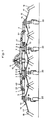
- the machine according to the invention comprises a support frame (1) of elongated shape.
- This chassis consists of a central part (2) and two lateral parts (3 and 4) which are articulated at the ends of said central part by means of pivots (5 and 6) which are substantially horizontal.
- This central part (2) is itself constituted by two longitudinal members (7 and 8) which are substantially parallel and which are connected together by means of plates (9). To the spar (7) is connected a connecting beam (10) which extends substantially perpendicular to the chassis (1) and the other end of which carries a coupling trestle (11).
- This easel (11) is provided with three coupling points serving to fix the machine to the three-point coupling device of a drive tractor not shown.
- the central part (2) of the chassis (1) carries two raking wheels (12 and 13) while each of the lateral parts (3 and 4) carries a raking wheel (14 and 15) at its end the more distant.
- Said wheels (12 to 15) are located directly under the central part (2) and the lateral parts (3 and 4) of the chassis (1). They are all substantially identical.
- Each consists of a hub (16) to which are fixed several arms (17) carrying working forks (18) at their outer ends.
- Each hub (16) is mounted so as to be able to rotate on a fixed axis (19) substantially vertical or inclined in the direction of advance of the machine.
- These axes (19) are connected to the chassis (1) and carry at their lower ends rollers (20) allowing the machine to be moved on the ground during work.
- the four raking wheels are substantially aligned. They are rotated in a manner known per se from the PTO shaft of the drive tractor.
- drive shafts (21) provided with pinions (22) which cooperate with toothed rings (23) connected to the hubs (16) are housed in the parts (3, 4 and 8) of the chassis (1). (see figure 5).
- the raking wheels (12 and 14) and the raking wheels (13 and 15) then rotate in convergence at the front - seen in the direction of travel -.
- their forks (18) move the forage and provide excellent tedding.
- raking wheels intended for making swaths or that can carry out both tedding and swathing can be provided on this machine.
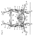
- each jack (24) is articulated to the central part (2) of the chassis (1) by means of an axis (25) and to the lateral part (3 or 4) corresponding to the means an axis (26).
- the actuation of these jacks (24) is advantageously done from the tractor. They can be double or single acting. In the latter case, the lateral parts (3 and 4) return to the working position under the effect of their own weight.
- the drive shafts (21) of the outer raking wheels (14 and 15) have articulations at the pivots (5 and 6), so as to be able to pivot with the lateral parts (3 and 4) of the chassis (1).
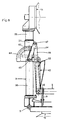
- one or each lateral part (3 or 4) of the chassis (1) comprises a pivot axis (27) making it possible to modify the position of the raking wheel (14 or 15) which is fixed to this lateral part (3 or 4) when it is moved around the pivot (5 or 6).
- the pivoting around this axis (27) makes it possible to reduce more space requirement of the machine.
- it makes it possible to modify the orientation of the forks (18) of the raking wheels (14 and 15) when they are raised, in order to reduce the risk of collision.
- each pivot axis (27) coincides with the longitudinal axis (28) of the corresponding lateral part (3 or 4) of the chassis (1).
- This position allows the raking wheels (14 and 15) to be brought closer to the center part (2) of the chassis (1) and to bring them above this part, by simply rotating them around 180 around these axes ( 27). The width of the machine is then reduced and the forks (18) of these raking wheels (14 and 15) are oriented towards the middle of the machine.
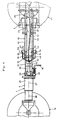
- the corresponding lateral part (3 or 4) is produced in two segments (29 and 30) nested one inside the other.
- the outer segment (29) to which the raking wheel (14 or 15) is connected can rotate relative to the inner segment (30) about the longitudinal axis (28).
- Said outer segment (29) has a sheath (31) into which the end of the inner segment (30) penetrates.
- Each segment (29 and 30) is provided with a flange (32 and 33). These flanges (32 and 33) form stops limiting the interlocking of the two segments (29 and 30).
- the outer segment (29) is additionally retained axially by means of flanges (34) fixed by means of screws on supports (35) welded to the inner segment (30).
- the inner segment (30) also includes a lock (36) for immobilizing the outer segment (29) in rotation during work or transport.
- This lock (36) which is guided in a lug (37) and in the flange (33) of the inner segment (30), can be introduced into two holes provided in the flange (32) of the outer segment (29). These orifices correspond respectively to the working position and to the transport or storage position of the segment (29) and of the outer raking wheel (14 or 15) which is attached thereto.
- the lock (36) is held in the locked position by a spring (38) and in the unlocked position by a stop (39).
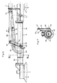
- Each side part (3 or 4) of the chassis (1) is associated with a control device (40 or 41) for its movements around its pivot (5 or 6) (see in particular Figures 3 and 4).
- Each of these devices (40 or 41) consists of two telescopic parts (42 and 43) produced by means of side members (44 and 45) and (46 and 47).
- the sliding part (42) of each control device (40 or 41) is articulated on the internal segment (30) of the lateral part (3 or 4) of the frame (1) while the non-sliding part (43) is articulated on the plate (9) of the central part (2) of said chassis.
- Said articulations are provided by means of the pins (25 and 26) also serving to articulate the hydraulic cylinders (24) as described above.
- the control devices (40, 41) retract or stretch depending on whether one passes into the transport position or the working position.
- the sliding part (42) has a movable stop (48) and the non-sliding part (43) has a stop (49) and an adjustable stop (50).
- said movable stop (48) is located between the adjustable stop (50) and the stop (49) of the non-sliding part (43).
- she paints moving between this stop (49) and the adjustable stop (50) so as to allow the lateral part (3 or 4) of the chassis (1) and the corresponding raking wheel (14 or 15) to follow uneven ground.
- adjustable stops (50) In order to be able to bring the lateral parts (3 and 4) of the chassis (1) to the transport position, the adjustable stops (50) must first be released. This obligation prevents accidental lifting of said lateral parts.
- These adjustable stops (50) consist of two fingers (51 and 52) mounted so as to be able to rotate and slide axially in housings (53 and 54) provided on the side members (46 and 47) of the non-sliding part (43). of each control device (40 or 41). Said fingers are interconnected by means of a stirrup (55) which is used for their adjustment. This stirrup (55) is made like a spring, so that it pushes these fingers (51 and 52) in the position in which they limit the displacements of the sliding part (42). This position is shown in Figure 4.
- Each of the housings (53 and 54) has an inclined ramp (56 and 57). These ramps (56 and 57) are symmetrical with respect to the longitudinal axis (28). Each of the legs of the stirrup (55) rests against one of these ramps (56 and 57) and can be moved along the corresponding ramp by simple pivoting around the axis (58) of the fingers ( 51 and 52). This pivoting can be ensured by means of a cable (59) making it possible to pull the stirrup (55) in the direction indicated by the arrow (F). This cable (59) is advantageously accessible from the seat of the drive tractor. During said movement of the two legs of the stirrup (55), they move apart and move the fingers axially (51 and 52).
- the two lateral parts (3 and 4) of the chassis (1) can be locked by means of these same fingers (51 and 52).
- the side members (44 and 45) of the sliding part (42) of each control device (40, 41) have holes (61) in which the ends of the fingers (51 and 52) can engage as soon as the transport position is reached.
- This engagement is effected by simple return of the stirrup (55) and consequently of the fingers (51 and 52) in the position they occupy during work.
- This return is done automatically by sliding of the legs of the stirrup (55) along the ramps (56 and 57), which sliding is obtained thanks to the constitution of this stirrup (55) like a spring, and after loosening of the cable ( 59).
- the lateral parts (3 and 4) of the chassis (1) can then be folded down around the pivots (5 and 6). This folding can be obtained either under the effect of the own weight of these side parts (3 and 4), or by means of hydraulic cylinders (24) if they are double acting.
- the fingers (51 and 52) are held in the out-of-service position by the side members (44 and 45) of the sliding parts (42) of the control devices (40 and 41) .
- each of the side parts (3 and 4) has a toothed sector (62) which surrounds it over approximately 180 ° .
- a second toothed sector (63) in the form of a circular arc, which cooperates with said sector (62), is provided on a rod (64) articulated on the one hand on the internal segment (30) of the lateral part (3 or 4) by means of an axis (65) on the other hand on a rod (66) by means of an axis (67).
- This rod (66) is itself articulated on the central part (2) of the chassis by means of the axis (25).
- toothed sectors (62 and 63) also prevent any displacement of the outer segments (29) of the lateral parts (3 and 4) of the chassis (1) relative to their inner segments (30), both in the working position and in the transport position.
- a twisted rod (70) of at least 180 ° is used to combine the pivoting of each outer raking wheel (14 and 15) around its axis (27) with the displacement around the pivots (5 and 6).
- This rod (70) is engaged in a guide (71) secured to the non-sliding part (43) of the corresponding control device (40 or 41).
- Said rod and the housing in the guide (71) in which it is fitted, have a polygonal section. In the example shown, said section is square.
- This rod is also connected to the outer segment (29) of the lateral part (3 or 4) of the chassis (1) by means of a crank (72) and a connecting rod (73) which are hinged together by a axis (74).
- Said crank (72) is guided in a bearing (75) integral with the internal segment (30) of the lateral part (3 or 4) and is connected to the twisted rod (70) by means of a universal joint (76).
- This joint allows a modification of its position relative to the rod.
- the connecting rod (73) is itself articulated to the outer segment (29) by means of an axis (77) substantially parallel to the latter. This axis (77) is engaged in a lug (78) welded on the periphery of said segment (29) and this, practically on the side opposite to that on which is locate the corresponding outer raking wheel (14 or 15).
- the forces on the rod (70) are greater due to the resistance of the forage and the friction of the working forks (18) on the ground.
- the rod (70) has a straight part (79) at its end. This straight part allows the outer raking wheels (14 and 15) to follow the unevenness of the ground during work, without these displacements causing a start of rotation around the pivot axes (27).
Landscapes
- Life Sciences & Earth Sciences (AREA)
- Environmental Sciences (AREA)
- Harvesting Machines For Root Crops (AREA)
- Harvester Elements (AREA)
- Agricultural Machines (AREA)
- Handcart (AREA)
- Vehicle Cleaning, Maintenance, Repair, Refitting, And Outriggers (AREA)
- Harvesting Machines For Specific Crops (AREA)
- Channel Selection Circuits, Automatic Tuning Circuits (AREA)
Claims (20)
Priority Applications (1)
| Application Number | Priority Date | Filing Date | Title |
|---|---|---|---|
| AT86440037T ATE48735T1 (de) | 1985-05-21 | 1986-05-16 | Heuerntemaschinen mit mehreren rechenraedern. |
Applications Claiming Priority (2)
| Application Number | Priority Date | Filing Date | Title |
|---|---|---|---|
| FR8507825A FR2582186B1 (fr) | 1985-05-21 | 1985-05-21 | Perfectionnement aux machines de fenaison munies de plusieurs roues rateleuses |
| FR8507825 | 1985-05-21 |
Publications (3)
| Publication Number | Publication Date |
|---|---|
| EP0203023A1 EP0203023A1 (de) | 1986-11-26 |
| EP0203023B1 EP0203023B1 (de) | 1989-12-20 |
| EP0203023B2 true EP0203023B2 (de) | 1994-08-24 |
Family
ID=9319527
Family Applications (1)
| Application Number | Title | Priority Date | Filing Date |
|---|---|---|---|
| EP86440037A Expired - Lifetime EP0203023B2 (de) | 1985-05-21 | 1986-05-16 | Heuerntemaschinen mit mehreren Rechenrädern |
Country Status (8)
| Country | Link |
|---|---|
| US (1) | US4723404A (de) |
| EP (1) | EP0203023B2 (de) |
| AT (1) | ATE48735T1 (de) |
| DE (1) | DE3667587D1 (de) |
| DK (1) | DK169374B1 (de) |
| ES (1) | ES8704067A1 (de) |
| FR (1) | FR2582186B1 (de) |
| HU (1) | HU202346B (de) |
Families Citing this family (40)
| Publication number | Priority date | Publication date | Assignee | Title |
|---|---|---|---|---|
| DE8602563U1 (de) * | 1986-01-31 | 1987-04-16 | Klöckner-Humboldt-Deutz AG Zweigniederlassung Fahr, 7702 Gottmadingen | Kreiselzettwender |
| DE3632767A1 (de) * | 1986-09-26 | 1988-03-31 | Kloeckner Humboldt Deutz Ag | Kreiselheuwerbungsmaschine |
| DE3641116C2 (de) * | 1986-12-02 | 1999-01-28 | Poettinger Alois Landmasch | Heuwerbungsmaschine |
| DE3709097A1 (de) * | 1987-03-20 | 1988-09-29 | Khd Agrartechnik | Kreiselheuwerbungsmaschine |
| EP0289864B1 (de) * | 1987-04-22 | 1992-09-30 | H. Niemeyer Söhne GmbH & Co. KG | Heuwerbungsmaschine |
| DE3713474A1 (de) * | 1987-04-22 | 1988-11-03 | Niemeyer Gmbh & Co Kg Soehne | Heuwerbungsmaschine |
| DE8716632U1 (de) * | 1987-05-20 | 1988-07-28 | Klöckner-Humboldt-Deutz AG, 5000 Köln | Heuwerbungsmaschine |
| FR2618045B1 (fr) * | 1987-07-15 | 1990-06-08 | Kuhn Sa | Machine de fenaison munie de plusieurs roues rateleuses basculables en vue du repliement pour le transport ou le remisage |
| DE8814293U1 (de) * | 1988-11-15 | 1990-03-22 | Alois Pöttinger Landmaschinen-Gesellschaft mbH, 8900 Augsburg | Heuwerbungsmaschine |
| FR2643783B1 (fr) * | 1989-03-01 | 1992-01-17 | Kuhn Sa | Machine de fenaison comportant plusieurs rotors |
| FR2661312B1 (fr) * | 1990-04-27 | 1992-07-17 | Kuhn Sa | Machine de fenaison avec plusieurs rotors. |
| DE4015767A1 (de) * | 1990-05-16 | 1991-11-21 | Poettinger Alois Landmasch | Heuwerbungsmaschine |
| DE4107528A1 (de) * | 1991-03-08 | 1992-09-10 | Heissenberger & Pretzler Gmbh | Heuwerbungsmaschine |
| FR2678804B1 (fr) * | 1991-07-11 | 1998-09-18 | Kuhn Sa | Machine de fenaison comportant au moins une roue rateleuse, un dispositif de protection et un deflecteur reglable. |
| DE4142496C2 (de) * | 1991-12-21 | 1996-05-15 | Krone Bernhard Gmbh Maschf | Heuwerbungsmaschine |
| DE9216498U1 (de) * | 1992-12-03 | 1993-02-11 | H. Niemeyer Söhne GmbH & Co KG, 4446 Hörstel | Heuwerbungsmaschine |
| FR2718324B1 (fr) * | 1994-04-12 | 1996-06-14 | Kuhn Sa | Machine de fenaison, notamment un andaineur, avec au moins un dispositif d'arrêt du rotor. |
| FR2722365B1 (fr) * | 1994-07-13 | 1996-09-20 | Kuhn Sa Societe Anonyme | Machine de fenaison, notamment une andaineuse de vegetaux a bras porte-fourches commandes |
| FR2731873B1 (fr) * | 1995-03-20 | 1997-06-13 | Kuhn Sa | Machine de fenaison, notamment une faneuse de vegetaux, transposable dans plusieurs positions |
| FR2740652B1 (fr) * | 1995-11-07 | 1998-01-30 | Kuhn Sa | Machine de fenaison comportant au moins un rotor d'andainage et permettant notamment une meilleure adaptation du rotor au relief du terrain |
| FR2746577B1 (fr) * | 1996-03-29 | 1998-05-29 | Kuhn Sa | Machine de fenaison comportant un dispositif de protection deplacable |
| FR2754136B1 (fr) * | 1996-10-03 | 1999-01-22 | Kuhn Sa | Machine de fenaison comportant un chassis compose de plusieurs troncons articules entre eux |
| FR2756137B1 (fr) * | 1996-11-26 | 1999-01-22 | Kuhn Sa | Machine de fenaison, notamment une andaineuse avec un deflecteur d'andainage reglage automatiquement dans differentes positions |
| DE19827401C1 (de) * | 1998-06-19 | 1999-12-16 | Claas Saulgau Gmbh | Heuwerbungsmaschine mit wenigstens zwei als Rechkreisel ausgeführten Arbeitsorganen |
| FR2828988B1 (fr) * | 2001-09-06 | 2004-07-30 | Kuhn Sa | Machine de fenaison comportant des rotors lies a des bras porteurs realises en deux parties telescopiques |
| US6865873B2 (en) * | 2002-06-21 | 2005-03-15 | Sitrex S.R.L. | Pull type V-shaped hay rake |
| US7793487B1 (en) | 2002-11-13 | 2010-09-14 | Wings Product Development Corporation | Pull type gang mower |
| US8166735B1 (en) * | 2002-11-13 | 2012-05-01 | Wing Product Development Corp. | Pull type gang mower |
| US6834488B2 (en) | 2002-11-22 | 2004-12-28 | Sitrex S.R.L. | Towable hay rake with an automatic steering mechanism |
| US20080256916A1 (en) * | 2007-04-17 | 2008-10-23 | Michael Vaske | Raking Device Disposed Between Outer Raking Devices |
| ITUD20070232A1 (it) * | 2007-12-06 | 2009-06-07 | Tonutti S P A Ind Macchine A G | Macchina agricola per rastrellare prodotti agricoli |
| IT1393791B1 (it) * | 2009-04-23 | 2012-05-08 | Tonutti S P A Ind Macchine Agricole Ora Tonutti Wolagri Spa Con Socio Unico | Macchina agricola per rastrellare prodotti agricoli |
| NL1037784C2 (nl) * | 2010-03-08 | 2011-09-09 | Forage Innovations Bv | Hooibouwinrichting. |
| DE102011100383B4 (de) † | 2011-05-04 | 2015-11-12 | Maschinenfabrik Bernard Krone Gmbh | Heuwerbungsmaschine |
| CA2897820A1 (en) * | 2014-07-15 | 2016-01-15 | Pequea Machine, Inc. | Frame suspension for rotary rakes and tedders |
| GB201814800D0 (en) * | 2018-09-12 | 2018-10-24 | Agco Feucht Gmbh | Improved agricultural implement |
| PL239447B1 (pl) * | 2019-10-14 | 2021-11-29 | Univ Warminsko Mazurski W Olsztynie | Przetrząsaczo-zgrabiarka kołowo palcowa |
| GB201915531D0 (en) * | 2019-10-25 | 2019-12-11 | Agco Int Gmbh | Improved agricultural implement |
| GB202107497D0 (en) * | 2021-05-26 | 2021-07-07 | Agco Int Gmbh | Agricultural apparatus |
| GB202108163D0 (en) * | 2021-06-08 | 2021-07-21 | Agco Int Gmbh | Towed agricultural apparatus |
Family Cites Families (18)
| Publication number | Priority date | Publication date | Assignee | Title |
|---|---|---|---|---|
| DE465846C (de) * | 1928-09-27 | Karl Pagels | Egge mit zwei um senkrechte Achsen rotierenden und durch Umstellen als Laufraeder dienenden Eggenkoerpern | |
| US2598959A (en) * | 1945-10-08 | 1952-06-03 | Deere & Co | Angling means for disk harrows |
| FR1176046A (fr) * | 1957-06-15 | 1959-04-03 | Herse portée perfectionnée | |
| CH363835A (de) * | 1958-07-15 | 1962-08-15 | Althaus & Co Pflugfabrik | Traktor-Eggenträger |
| FR1346993A (fr) * | 1961-07-14 | 1963-12-27 | Fahr Ag Maschf | Dispositif facilitant le transport par route de machines de fenaison comportant plus de deux croisillons à dents |
| FR1455939A (fr) * | 1965-07-07 | 1966-05-20 | Fahr Ag Maschf | Perfectionnements apportés aux machines de fenaison |
| DE1266556B (de) * | 1966-06-24 | 1968-04-18 | Fahr Ag Maschf | Gelenkverbindung zwischen den Abschnitten einer mit Tragrohren versehenen Gelenkwelle |
| CH465947A (de) * | 1967-04-26 | 1968-11-30 | Bautz Gmbh Josef | Kreiselzettwender |
| DE1757499C3 (de) * | 1968-05-16 | 1974-09-26 | Maschinenfabrik Fahr Ag Gottmadingen, 7702 Gottmadingen | Kreiselzettwender |
| US3941194A (en) * | 1970-12-23 | 1976-03-02 | Orthman Manufacturing, Inc. | Folding tool bar having a transport brace |
| NL167834C (nl) * | 1971-11-05 | 1982-02-16 | Lely Nv C Van Der | Hooibouwmachine. |
| NL7308237A (de) * | 1973-06-13 | 1974-12-17 | ||
| FR2270772A1 (en) * | 1973-12-03 | 1975-12-12 | Heinrich Henri | Harrow with folding side sections - has pairs of pins locking for pivot sleeves of side sections |
| DE2410453A1 (de) * | 1974-03-05 | 1975-09-11 | Schlittler Jacques Roby Dr | Heuwerbungsmaschine |
| NL177070C (nl) * | 1979-08-24 | 1985-08-01 | Lely Nv C Van Der | Hooibouwmachine. |
| US4342367A (en) * | 1980-10-21 | 1982-08-03 | Alloway Manufacturing, Inc. | Folding tool bar |
| DE3342962A1 (de) * | 1983-01-12 | 1984-07-12 | Jean Sion Bützberger | Mehrteiliger, gelenkiger ausleger |
| FR2548519B1 (fr) * | 1983-07-07 | 1986-04-04 | Kuhn Sa | Perfectionnement aux machines de fenaison en vue de leur transport |
-
1985
- 1985-05-21 FR FR8507825A patent/FR2582186B1/fr not_active Expired
-
1986
- 1986-04-23 ES ES554261A patent/ES8704067A1/es not_active Expired
- 1986-04-25 HU HU861731A patent/HU202346B/hu not_active IP Right Cessation
- 1986-05-12 US US06/861,988 patent/US4723404A/en not_active Expired - Lifetime
- 1986-05-16 DE DE8686440037T patent/DE3667587D1/de not_active Expired - Lifetime
- 1986-05-16 EP EP86440037A patent/EP0203023B2/de not_active Expired - Lifetime
- 1986-05-16 DK DK231986A patent/DK169374B1/da not_active IP Right Cessation
- 1986-05-16 AT AT86440037T patent/ATE48735T1/de not_active IP Right Cessation
Also Published As
| Publication number | Publication date |
|---|---|
| DE3667587D1 (de) | 1990-01-25 |
| EP0203023B1 (de) | 1989-12-20 |
| EP0203023A1 (de) | 1986-11-26 |
| DK231986D0 (da) | 1986-05-16 |
| ES8704067A1 (es) | 1987-04-01 |
| FR2582186A1 (fr) | 1986-11-28 |
| DK231986A (da) | 1986-11-22 |
| ATE48735T1 (de) | 1990-01-15 |
| ES554261A0 (es) | 1987-04-01 |
| FR2582186B1 (fr) | 1989-05-05 |
| DK169374B1 (da) | 1994-10-17 |
| HU202346B (en) | 1991-03-28 |
| US4723404A (en) | 1988-02-09 |
| HUT40872A (en) | 1987-03-30 |
Similar Documents
| Publication | Publication Date | Title |
|---|---|---|
| EP0203023B1 (de) | Heuerntemaschinen mit mehreren Rechenrädern | |
| EP0429381B1 (de) | Landmaschine mit verbesserter Aufhängungsvorrichtung der Arbeitswerkzeugeeinheit | |
| EP0403409B1 (de) | Landmaschine zum Schwaden mit zusammenklappbaren Werkzeugträgern | |
| FR2643783A1 (fr) | Machine de fenaison comportant plusieurs rotors | |
| EP0131530A1 (de) | Transport von Heuwerbungsmaschinen | |
| EP0300937B1 (de) | Heuwerbungsmaschine mit mehreren einschwenkbaren Rechrädern zum Zusammenlegen für den Transport oder die Unterbringung | |
| FR2838284A1 (fr) | Machine de fenaison avec des bras porteurs de rotors pouvant etre verrouilles en position de transport | |
| EP0517632B1 (de) | Landmaschine, insbesondere ein Pflanzenschwader | |
| EP0310532B2 (de) | Heuwendemaschine mit einer verbesserten Schutzvorrichtung | |
| EP1142468A1 (de) | Heuwerbungsmaschine | |
| FR2664127A1 (fr) | Machine agricole, notamment une andaineuse de vegetaux, a largeur de travail reglable. | |
| FR2705861A1 (fr) | Machine de fenaison avec un dispositif de transport déplaçable. | |
| EP0797913B1 (de) | Heuwerbungsmaschine | |
| EP0554200B1 (de) | Heuwerbungsmaschine mit einem mit gesteuerten Stützrädern versehenen Rahmen | |
| EP0654209B1 (de) | Heuwerbungsmaschine | |
| EP0733302B1 (de) | Heuwerbungsmaschine | |
| FR2707450A1 (fr) | Machine de fenaison avec des rotors de fanage ou d'andainage munis de roues d'appui au sol. | |
| EP0426588A1 (de) | Verbesserung für landwirtschaftliche Maschinen insbesondere für Heuwerbungsmaschinen | |
| FR2612362A1 (fr) | Machine centrifuge pour la fenaison | |
| EP0593378B1 (de) | Heuwerbungsmaschine zum Schwaden von Halmgut | |
| FR2664790A3 (fr) | Machine de fenaison. | |
| FR2742304A1 (fr) | Machine de fenaison, notamment une andaineuse de vegetaux coupes, comportant des rotors d'andainage relies par une poutre | |
| FR2662908A1 (fr) | Machine pour la fenaison. | |
| FR2699044A1 (fr) | Machine de fenaison avec des roues de transport déplaçables en hauteur. | |
| EP0811314B1 (de) | Landmaschine |
Legal Events
| Date | Code | Title | Description |
|---|---|---|---|
| PUAI | Public reference made under article 153(3) epc to a published international application that has entered the european phase |
Free format text: ORIGINAL CODE: 0009012 |
|
| AK | Designated contracting states |
Kind code of ref document: A1 Designated state(s): AT BE CH DE GB IT LI NL SE |
|
| 17P | Request for examination filed |
Effective date: 19870312 |
|
| 17Q | First examination report despatched |
Effective date: 19880411 |
|
| GRAA | (expected) grant |
Free format text: ORIGINAL CODE: 0009210 |
|
| AK | Designated contracting states |
Kind code of ref document: B1 Designated state(s): AT BE CH DE GB IT LI NL SE |
|
| REF | Corresponds to: |
Ref document number: 48735 Country of ref document: AT Date of ref document: 19900115 Kind code of ref document: T |
|
| REF | Corresponds to: |
Ref document number: 3667587 Country of ref document: DE Date of ref document: 19900125 |
|
| ITF | It: translation for a ep patent filed | ||
| GBT | Gb: translation of ep patent filed (gb section 77(6)(a)/1977) | ||
| PLBI | Opposition filed |
Free format text: ORIGINAL CODE: 0009260 |
|
| 26 | Opposition filed |
Opponent name: HEISSENBERGER & PRETZLER GMBH Effective date: 19900919 |
|
| NLR1 | Nl: opposition has been filed with the epo |
Opponent name: HEISSENBERGER & PRETZLER GMBH. |
|
| ITTA | It: last paid annual fee | ||
| PUAA | Information related to the publication of a b2 document modified |
Free format text: ORIGINAL CODE: 0009299PMAP |
|
| PUAH | Patent maintained in amended form |
Free format text: ORIGINAL CODE: 0009272 |
|
| STAA | Information on the status of an ep patent application or granted ep patent |
Free format text: STATUS: PATENT MAINTAINED AS AMENDED |
|
| 27A | Patent maintained in amended form |
Effective date: 19940824 |
|
| AK | Designated contracting states |
Kind code of ref document: B2 Designated state(s): SE |
|
| REG | Reference to a national code |
Ref country code: CH Ref legal event code: AEN |
|
| ITF | It: translation for a ep patent filed | ||
| R27A | Patent maintained in amended form (corrected) |
Effective date: 19940824 |
|
| NLR2 | Nl: decision of opposition | ||
| GBT8 | Gb: translation filed (gb section 80(3)/1977) | ||
| GBTA | Gb: translation of amended ep patent filed (gb section 77(6)(b)/1977) |
Effective date: 19941006 |
|
| NLR3 | Nl: receipt of modified translations in the netherlands language after an opposition procedure | ||
| EAL | Se: european patent in force in sweden |
Ref document number: 86440037.9 |
|
| REG | Reference to a national code |
Ref country code: GB Ref legal event code: IF02 |
|
| PGFP | Annual fee paid to national office [announced via postgrant information from national office to epo] |
Ref country code: AT Payment date: 20050421 Year of fee payment: 20 |
|
| PGFP | Annual fee paid to national office [announced via postgrant information from national office to epo] |
Ref country code: SE Payment date: 20050425 Year of fee payment: 20 Ref country code: CH Payment date: 20050425 Year of fee payment: 20 |
|
| PGFP | Annual fee paid to national office [announced via postgrant information from national office to epo] |
Ref country code: NL Payment date: 20050426 Year of fee payment: 20 Ref country code: BE Payment date: 20050426 Year of fee payment: 20 |
|
| PGFP | Annual fee paid to national office [announced via postgrant information from national office to epo] |
Ref country code: GB Payment date: 20050427 Year of fee payment: 20 |
|
| PGFP | Annual fee paid to national office [announced via postgrant information from national office to epo] |
Ref country code: DE Payment date: 20050502 Year of fee payment: 20 |
|
| PGFP | Annual fee paid to national office [announced via postgrant information from national office to epo] |
Ref country code: IT Payment date: 20050527 Year of fee payment: 20 |
|
| REG | Reference to a national code |
Ref country code: GB Ref legal event code: PE20 |
|
| APAH | Appeal reference modified |
Free format text: ORIGINAL CODE: EPIDOSCREFNO |
|
| PG25 | Lapsed in a contracting state [announced via postgrant information from national office to epo] |
Ref country code: GB Free format text: LAPSE BECAUSE OF EXPIRATION OF PROTECTION Effective date: 20060515 |
|
| PG25 | Lapsed in a contracting state [announced via postgrant information from national office to epo] |
Ref country code: NL Free format text: LAPSE BECAUSE OF EXPIRATION OF PROTECTION Effective date: 20060516 |
|
| REG | Reference to a national code |
Ref country code: CH Ref legal event code: PL |
|
| NLV7 | Nl: ceased due to reaching the maximum lifetime of a patent |
Effective date: 20060516 |
|
| EUG | Se: european patent has lapsed | ||
| BE20 | Be: patent expired |
Owner name: S.A. *KUHN Effective date: 20060516 |
|
| PLAB | Opposition data, opponent's data or that of the opponent's representative modified |
Free format text: ORIGINAL CODE: 0009299OPPO |