EP0203320A2 - Commande variable des soupapes pour un moteur à combustion interne - Google Patents
Commande variable des soupapes pour un moteur à combustion interne Download PDFInfo
- Publication number
- EP0203320A2 EP0203320A2 EP86104645A EP86104645A EP0203320A2 EP 0203320 A2 EP0203320 A2 EP 0203320A2 EP 86104645 A EP86104645 A EP 86104645A EP 86104645 A EP86104645 A EP 86104645A EP 0203320 A2 EP0203320 A2 EP 0203320A2
- Authority
- EP
- European Patent Office
- Prior art keywords
- valve
- camshaft
- control according
- valve control
- combustion engine
- Prior art date
- Legal status (The legal status is an assumption and is not a legal conclusion. Google has not performed a legal analysis and makes no representation as to the accuracy of the status listed.)
- Ceased
Links
Images

Classifications
-
- F—MECHANICAL ENGINEERING; LIGHTING; HEATING; WEAPONS; BLASTING
- F01—MACHINES OR ENGINES IN GENERAL; ENGINE PLANTS IN GENERAL; STEAM ENGINES
- F01L—CYCLICALLY OPERATING VALVES FOR MACHINES OR ENGINES
- F01L13/00—Modifications of valve-gear to facilitate reversing, braking, starting, changing compression ratio, or other specific operations
- F01L13/0015—Modifications of valve-gear to facilitate reversing, braking, starting, changing compression ratio, or other specific operations for optimising engine performances by modifying valve lift according to various working parameters, e.g. rotational speed, load, torque
- F01L13/0021—Modifications of valve-gear to facilitate reversing, braking, starting, changing compression ratio, or other specific operations for optimising engine performances by modifying valve lift according to various working parameters, e.g. rotational speed, load, torque by modification of rocker arm ratio
Definitions
- the invention relates to a variable valve control of a reciprocating piston internal combustion engine according to the preamble of claim 1.
- the actuating mechanism consists of a lifting camshaft driven by the crankshaft, which acts on an intake valve of an internal combustion engine via a double-armed, pivotable valve lever and a second cam, which can be phase-rotated relative to the lifting camshaft.
- the bearing axis of the valve lever can be displaced with an eccentric relative to the axes of the lifting camshaft and the second cam.
- the angular position of the second cam relative to the lifting camshaft can be controlled as a function of the load and speed of the internal combustion engine.
- the object of the invention is to provide a variable valve control which can be produced at low manufacturing costs and with which the valve lift curve can be changed in such a way that charge exchange losses caused by throttling are avoided without this necessitating a change in further setting variables of the internal combustion engine.
- valve lever is mounted on a crank which can be pivoted at a fixed bearing point of the cylinder head.
- the valve lever according to the invention has an additional degree of freedom, since it can also be pivoted about two axes.
- a roller is mounted on the crank, which acts on the rotating control camshaft.
- the control camshaft has a circular segment as a cam, the angular extent of which is equal to the angular extent of the cam of the lifting camshaft. If the relative positions of the lifting camshaft and the control camshaft are set such that the circular segment of the control camshaft also acts on the valve lever over the entire angular extent of the lifting camshaft, the valve lever executes a pivoting movement as if it were mounted in a conventional manner on a stationary pin.
- valve lever can deflect in the direction of the base circle of the control cam when the lifting cam opens, so that the inlet valve is not fully opened and is closed again prematurely.
- the amount of charge supplied to the cylinder is reduced.
- the unrestricted intake and the higher pressure upstream of the inlet valve reduce the residual gas content, which improves combustion and efficiency.
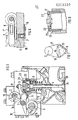
- a pin 7 'of a crank 7 is mounted on a fixed bearing 6 of the internal combustion engine, on the other pin 7' 'of which the rocker arm 3 and a roller 8 are mounted, on which the control camshaft 2 acts.
- a single-arm rocker arm 3 ' is used as the valve lever, which is pivotally mounted on one side on the crank 7 and can be actuated at this point by the control camshaft 2 via the roller 8, whereas the lifting camshaft 1 approximately attacks centrally on the rocker arm 3 '.
- a two-armed rigid rocker arm 3 is used as the valve lever, which is, however, mounted on a resilient bearing journal 9, which is displaceable by the control camshaft 2 via the roller 8 fitted onto it.
- the lifting camshaft 1 and the control camshaft 2 are rotatably supported, which are driven by the crankshaft 11 and which both rotate at the same speed.
- the control camshaft 2 and the lifting camshaft 1 engage on the rocker arm 3 mounted on the crank 7, one arm of the rocker arm 3 resting on the cam base circle 12 of the lifting camshaft 1, whereas the roller 8, which is mounted on the crank pin 7 ", still has no contact with the control camshaft 2.
- the inlet valve 4 is still closed here. If the lifting camshaft 1 moves clockwise, the rocker arm 3 is pivoted about the pin 7 ′′ of the crank 7 in accordance with the cam elevation 15, the roller 8 now moving on supports the transition surface 13 to the circular segment 14.
- the inlet valve 4 is opened and, when the cam elevation 15 drops, closed again by the force of the valve spring 5.
- the roller 8 In the drawn relative rotational position of the lifting camshaft 1 and the control camshaft 2, the roller 8 remains throughout the angular path ⁇ H of the Lifting camshaft 1 in contact with the circular segment 14 of the Control camshaft 2, since the angular path ⁇ S of the circular segment 14 is dimensioned to be the same size as the angular path ⁇ H of the cam elevation 15 of the lifting camshaft 1.
- the valve lift curve h1 shown in FIG. 4 applies.
- the roller 8 comes out of the angular range ⁇ S of the circular segment 14 during a partial region of the elevation curve, the crank 7 swivels around the fixed bearing 6 and the inlet valve 4 closes prematurely.
- a stroke curve h2 shown in FIG. 4 is established. If the relative rotational position is further adjusted, a curve h3 with a further reduced time cross section can be achieved or the inlet valve can be stopped completely, so that a valve shutdown can be achieved in this way.
- the opening movement of the inlet valve 4 takes place on the same rising branch of the valve lift curve with a constant phase position, so that the overlap angle to the exhaust valve is the same for all valve lift curves achievable with the variable valve control.
- the control camshaft 2 only touches the roller 8 as long as the inlet valve 4 is open. So that a clear position of the rocker arm 3 relative to the lifting camshaft and the intake valve also results afterwards, the crank 7 and thus the rocker arm 3 'is pressed down by an additionally, only slightly preloaded spring 16.
- a toothed belt drive according to FIG. 7 can be used between the crankshaft 11 and the control camshaft 2.
- the load strand 17 and on the loose strand 18 of the toothed belt one tensioning roller 19 each, on a triangle Carrier 20 are stored and held.
- the triangular support 20 is pivoted about the axis of the crankshaft 11, the load run 17 is extended, the lost run 18 is shortened, so that the phase position of the control camshaft 2 relative to the crankshaft 11 and thus also to the lifting camshaft 1 driven by the crankshaft 11 is changed.
- a damping device shown enlarged in FIG. 8 consists of an oil-filled hydraulic cylinder 21 fastened in the cylinder head 10 of the internal combustion engine and a hollow hydraulic piston 22 guided therein.
- the power flow goes from the rocker arm 3 via the hydraulic piston 22 to the valve stem of the inlet valve 4. If that Inlet valve 4 closed by the valve spring 5, oil drain holes 23 of the hydraulic cylinder 21 are closed by the hydraulic piston 22 from a certain closed position, so that the mounting of the valve plate 24 on the valve seat 25 is delayed and strongly damped.
- An oil line 27 leads to the oil chamber 26 located between the hydraulic cylinder 21 and the hydraulic piston 22 and can be closed by a check valve.
- the oil drain bores 23 can be closed from the outside by a valve which can be controlled as a function of parameters of the internal combustion engine in order to make the damping adjustable.
Landscapes
- Engineering & Computer Science (AREA)
- Mechanical Engineering (AREA)
- General Engineering & Computer Science (AREA)
- Valve Device For Special Equipments (AREA)
- Valve-Gear Or Valve Arrangements (AREA)
Applications Claiming Priority (2)
| Application Number | Priority Date | Filing Date | Title |
|---|---|---|---|
| DE3519319 | 1985-05-30 | ||
| DE19853519319 DE3519319A1 (de) | 1985-05-30 | 1985-05-30 | Variable ventilsteuerung fuer eine hubkolben-brennkraftmaschine |
Publications (2)
| Publication Number | Publication Date |
|---|---|
| EP0203320A2 true EP0203320A2 (fr) | 1986-12-03 |
| EP0203320A3 EP0203320A3 (fr) | 1987-12-16 |
Family
ID=6271957
Family Applications (1)
| Application Number | Title | Priority Date | Filing Date |
|---|---|---|---|
| EP86104645A Ceased EP0203320A3 (fr) | 1985-05-30 | 1986-04-04 | Commande variable des soupapes pour un moteur à combustion interne |
Country Status (3)
| Country | Link |
|---|---|
| US (1) | US4714057A (fr) |
| EP (1) | EP0203320A3 (fr) |
| DE (1) | DE3519319A1 (fr) |
Cited By (1)
| Publication number | Priority date | Publication date | Assignee | Title |
|---|---|---|---|---|
| FR2700580A1 (fr) * | 1993-01-20 | 1994-07-22 | Meta Motoren En Technik Gmb | Système de commande variable pour soupapes dans un moteur à combustion interne. |
Families Citing this family (54)
| Publication number | Priority date | Publication date | Assignee | Title |
|---|---|---|---|---|
| DE3725448A1 (de) * | 1987-07-31 | 1989-02-09 | Rainer Bartsch | Ventilsteuerung zur variation von ventilhub und -oeffnungsdauer |
| DE3833540A1 (de) * | 1988-10-01 | 1990-04-12 | Peter Prof Dr Ing Kuhn | Vorrichtung zur betaetigung der ventile an verbrennungsmotoren mit veraenderlicher ventilerhebungskurve |
| US5507254A (en) * | 1989-01-13 | 1996-04-16 | Melchior; Jean F. | Variable phase coupling for the transmission of alternating torques |
| FR2641832B1 (fr) * | 1989-01-13 | 1991-04-12 | Melchior Jean | Accouplement pour la transmission de couples alternes |
| US5002023A (en) * | 1989-10-16 | 1991-03-26 | Borg-Warner Automotive, Inc. | Variable camshaft timing for internal combustion engine |
| DE4006950A1 (de) * | 1990-03-06 | 1991-09-12 | Bayerische Motoren Werke Ag | Regelverfahren zur drehzahlabhaengigen, stufenlosen verstellung der nockenspreizung |
| GB9018558D0 (en) * | 1990-08-23 | 1990-10-10 | Ricardo Group Plc | Valve gear for internal combustion engines |
| US5184401A (en) * | 1990-11-30 | 1993-02-09 | Mazda Motor Corporation | Method of assembling valve drive mechanism to engine |
| JPH04246249A (ja) * | 1991-01-31 | 1992-09-02 | Nissan Motor Co Ltd | 内燃機関の実圧縮比制御装置 |
| ATE158058T1 (de) * | 1991-04-24 | 1997-09-15 | Donald Charles Wride | Ventilantriebsvorrichtung |
| JP2944264B2 (ja) * | 1991-07-23 | 1999-08-30 | 株式会社ユニシアジェックス | 内燃機関の動弁装置 |
| DE4138527A1 (de) * | 1991-11-23 | 1993-05-27 | Volker Deuschle | Variable ventilsteuerung fuer brennkraftmaschine |
| US5732669A (en) * | 1992-12-13 | 1998-03-31 | Bayerische Motoren Werke Aktiengesellschaft | Valve control for an internal combustion engine |
| EP0626035B1 (fr) * | 1992-12-13 | 1997-08-13 | Bayerische Motoren Werke Aktiengesellschaft, Patentabteilung AJ-3 | Commande de soupape pour un moteur a combustion interne |
| DE4300684C2 (de) * | 1993-01-13 | 1994-10-13 | Meta Motoren Energietech | Ventiltrieb zur variablen Steuerung von Brennkraftmaschinen |
| DE4300487C2 (de) * | 1993-01-11 | 1994-10-13 | Meta Motoren Energietech | Vorrichtung zur Ventilspieleinstellung in variablen Ventilsteuerungen von Brennkraftmaschinen |
| US5586527A (en) * | 1992-12-30 | 1996-12-24 | Meta Motoren-Und Energie-Technik Gmbh | Device for the variable control of the valves of internal combustion engines, more particularly for the throttle-free load control of 4-stroke engines |
| DE4244550C2 (de) * | 1992-12-30 | 1998-05-28 | Meta Motoren Energietech | Vorrichtung zur Verdrehung von Nockenwellen von Brennkraftmaschinen |
| WO1994016202A1 (fr) * | 1992-12-30 | 1994-07-21 | Meta Motoren- Und Energie-Technik Gmbh | Dispositif permettant de commander de maniere variable les soupapes de moteurs a combustion interne, et notamment de commander sans papillon le circuit de puissance de moteurs a essence |
| GB2273956B (en) * | 1993-01-05 | 1996-04-17 | Peter David Stewart | An internal combustion engine incorporating variable valve lift |
| US5327859A (en) * | 1993-06-09 | 1994-07-12 | General Motors Corporation | Engine timing drive with fixed and variable phasing |
| DE4322480C2 (de) * | 1993-07-06 | 1996-05-02 | Meta Motoren Energietech | Vorrichtung zur variablen Ventilsteuerung von Brennkraftmaschinen |
| DE19501386C2 (de) * | 1995-01-18 | 1998-12-10 | Meta Motoren Energietech | Verfahren zum Steuern einer fremdgezündeten, mit einer Kraftstoffeinspritzanlage ausgerüsteten Kolbenbrennkraftmaschine |
| ES1040073Y (es) * | 1998-04-23 | 1999-07-16 | Martinez Jose Benlloch | Dispositivo perfeccionado para el accionamiento en las valvulas de distribucion variable para motores de combustion interna. |
| DE19920512A1 (de) | 1999-05-05 | 2000-11-09 | Opel Adam Ag | Vorrichtung zur Betätigung eines Ventiles mit variablem Hub an Brennkraftmaschinen |
| DE10006018B4 (de) * | 2000-02-11 | 2009-09-17 | Schaeffler Kg | Variabler Ventiltrieb zur Laststeuerung einer fremdgezündeten Brennkraftmaschine |
| JP2001355398A (ja) * | 2000-06-12 | 2001-12-26 | Denki Kagaku Kogyo Kk | トンネル防水方法 |
| US6793441B2 (en) * | 2000-06-12 | 2004-09-21 | W. R. Grace & Co.-Conn. | Tunnel waterproofing method |
| DE10052811A1 (de) * | 2000-10-25 | 2002-05-08 | Ina Schaeffler Kg | Variabler Ventiltrieb zur Laststeuerung einer fremdgezündeten Brennkraftmaschine |
| WO2003046355A1 (fr) * | 2001-11-26 | 2003-06-05 | Ina-Schaeffler Kg | Procede et dispositif de coordination du remplissage des cylindres d'un moteur a combustion interne a plusieurs cylindres |
| AU2003244097A1 (en) * | 2002-05-17 | 2003-12-02 | Koichi Hatamura | Engine valve driver |
| CA2486430A1 (fr) * | 2002-05-17 | 2003-11-27 | Yamaha Hatsudoki Kabushiki Kaisha | Dispositif d'entrainement de soupape de moteur |
| DE50202718D1 (de) | 2002-07-12 | 2005-05-12 | Avl List Gmbh | Ventiltriebseinrichtung |
| GB2395521A (en) * | 2002-11-23 | 2004-05-26 | Mechadyne Plc | Engine with variable valve mechanism |
| US6679207B1 (en) * | 2003-02-24 | 2004-01-20 | Caterpillar Inc | Engine valve actuation system |
| EP1605142B1 (fr) | 2003-03-11 | 2014-01-01 | Yamaha Hatsudoki Kabushiki Kaisha | Mecanisme de soupape variable pour moteur a combustion interne |
| JP4248344B2 (ja) | 2003-05-01 | 2009-04-02 | ヤマハ発動機株式会社 | エンジンの動弁装置 |
| JP4248343B2 (ja) * | 2003-05-01 | 2009-04-02 | ヤマハ発動機株式会社 | エンジンの動弁装置 |
| JP4247529B2 (ja) * | 2003-08-22 | 2009-04-02 | ヤマハ発動機株式会社 | 内燃機関の動弁機構 |
| JP2005069014A (ja) * | 2003-08-25 | 2005-03-17 | Yamaha Motor Co Ltd | 内燃機関の動弁機構 |
| JP4237643B2 (ja) | 2003-08-25 | 2009-03-11 | ヤマハ発動機株式会社 | 内燃機関の動弁機構 |
| US20050087159A1 (en) * | 2003-10-28 | 2005-04-28 | Caterpillar, Inc. | Engine valve actuation system |
| US7007650B2 (en) * | 2003-10-31 | 2006-03-07 | Caterpillar Inc | Engine valve actuation system |
| DE10357083A1 (de) * | 2003-12-06 | 2005-06-30 | Ina-Schaeffler Kg | Variabler Ventiltrieb |
| JP2006329084A (ja) | 2005-05-26 | 2006-12-07 | Yamaha Motor Co Ltd | エンジンの動弁装置 |
| JP2006329164A (ja) | 2005-05-30 | 2006-12-07 | Yamaha Motor Co Ltd | 複数気筒エンジン |
| JP4726775B2 (ja) | 2006-12-20 | 2011-07-20 | ヤマハ発動機株式会社 | エンジンの連続可変式動弁装置 |
| US8033261B1 (en) | 2008-11-03 | 2011-10-11 | Robbins Warren H | Valve actuation system and related methods |
| CN101429882B (zh) * | 2008-12-12 | 2011-07-13 | 奇瑞汽车股份有限公司 | 连续可变气门升程装置 |
| DE102009002843A1 (de) | 2009-05-06 | 2010-11-11 | Robert Bosch Gmbh | Vorrichtung zur variablen Hubsteuerung eines Ventils |
| WO2015177810A2 (fr) * | 2014-05-20 | 2015-11-26 | Indian Institute Of Technology Madras | Procédé d'adaptation et d'actionnement de came à profil variable pour commander le soulèvement et la synchronisation de soupapes de moteur |
| CN105909332B (zh) * | 2016-05-30 | 2019-07-12 | 苏立群 | 无极可变升程气门摇臂机构及相应气门装置 |
| DE102016122179A1 (de) * | 2016-11-18 | 2018-05-24 | Pierburg Gmbh | Mechanisch steuerbarer Ventiltrieb |
| DE102019134617A1 (de) * | 2019-12-16 | 2021-06-17 | Bayerische Motoren Werke Aktiengesellschaft | Vorrichtung zur Einstellung der Betriebsphasen der Ventile eines Verbrennungsmotors |
Family Cites Families (19)
| Publication number | Priority date | Publication date | Assignee | Title |
|---|---|---|---|---|
| BE333655A (fr) * | ||||
| US2021333A (en) * | 1931-11-13 | 1935-11-19 | Packard Motor Car Co | Internal combustion engine |
| US2065081A (en) * | 1934-01-25 | 1936-12-22 | Chrysler Corp | Valve operating mechanism |
| FR1172416A (fr) * | 1957-02-20 | 1959-02-10 | Perfectionnement aux moteurs à explosion ou à combustion | |
| US3463131A (en) * | 1968-03-12 | 1969-08-26 | John W Dolby | Valve operating mechanism |
| US3610218A (en) * | 1970-04-13 | 1971-10-05 | Roger Owen Durham | Desmodromic valve actuator |
| GB1399813A (en) * | 1971-10-25 | 1975-07-02 | Innovation Technical Dev Co Lt | Motion transmitting unit for use in varying the reciprocating movement of a member |
| US3995606A (en) * | 1976-02-02 | 1976-12-07 | Joseph Carl Firey | Gasoline engine torque regulator with speed correction |
| JPS55137305A (en) * | 1979-04-13 | 1980-10-27 | Nissan Motor Co Ltd | Valve lift for internal combustion engine |
| JPS55148910A (en) * | 1979-05-07 | 1980-11-19 | Nissan Motor Co Ltd | Device for moving valve |
| JPS55152308A (en) * | 1979-05-15 | 1980-11-27 | Tokunao Narumi | Combustion of pressure crematory |
| US4408580A (en) * | 1979-08-24 | 1983-10-11 | Nippon Soken, Inc. | Hydraulic valve lift device |
| DE3006619A1 (de) * | 1980-02-22 | 1981-08-27 | Audi Nsu Auto Union Ag, 7107 Neckarsulm | Vorrichtung zum verstellbaren betaetigen eines den ladungswechsel einer brennkraftmaschine steuernden ventils |
| JPS57195809A (en) * | 1981-05-27 | 1982-12-01 | Honda Motor Co Ltd | Variable valve timing device in engine |
| US4526142A (en) * | 1981-06-24 | 1985-07-02 | Nissan Motor Company, Limited | Variable valve timing arrangement for an internal combustion engine or the like |
| JPS59200910A (ja) * | 1983-04-28 | 1984-11-14 | Dainippon Printing Co Ltd | スポツト状欠陥判定装置 |
| DE3319637A1 (de) * | 1983-05-31 | 1984-12-06 | Mtu Motoren- Und Turbinen-Union Friedrichshafen Gmbh, 7990 Friedrichshafen | Ventilsteuerung fuer eine hubkolben-brennkraftmaschine |
| US4530318A (en) * | 1984-01-20 | 1985-07-23 | Carol M. Semple | Intake and exhaust valve system for internal combustion engine |
| DE3418361A1 (de) * | 1984-05-17 | 1984-10-18 | Herbert Dipl.-Ing. 8000 München Gohle | Vorrichtung zur verringerung der drosselverluste bei kolbenmotoren unter teillast durch phasenanschnittsteuerung der ventile |
-
1985
- 1985-05-30 DE DE19853519319 patent/DE3519319A1/de not_active Withdrawn
-
1986
- 1986-04-04 EP EP86104645A patent/EP0203320A3/fr not_active Ceased
- 1986-05-30 US US06/868,711 patent/US4714057A/en not_active Expired - Fee Related
Cited By (1)
| Publication number | Priority date | Publication date | Assignee | Title |
|---|---|---|---|---|
| FR2700580A1 (fr) * | 1993-01-20 | 1994-07-22 | Meta Motoren En Technik Gmb | Système de commande variable pour soupapes dans un moteur à combustion interne. |
Also Published As
| Publication number | Publication date |
|---|---|
| DE3519319A1 (de) | 1986-12-04 |
| EP0203320A3 (fr) | 1987-12-16 |
| US4714057A (en) | 1987-12-22 |
Similar Documents
| Publication | Publication Date | Title |
|---|---|---|
| EP0203320A2 (fr) | Commande variable des soupapes pour un moteur à combustion interne | |
| EP1387928B1 (fr) | Systeme de commande de soupape pour modifier la course d'une soupape de gaz a deux voies d'un moteur a combustion | |
| DE2855688C2 (fr) | ||
| EP0914546B1 (fr) | Mecanisme de distribution et culasse de moteur a combustion interne | |
| DE3872311T2 (de) | Nockenvorrichtungen. | |
| DE7005077U (de) | Ventilsteuerungseinrichtung fuer brennkraftmaschinen. | |
| WO1995002116A1 (fr) | Procede et dispositif de commande variable d'une soupape d'un moteur a combustion interne | |
| DE1751449B1 (de) | Otto-Brennkraftmaschine mit wahlweise einstellbaren Schwenkzapfen zur Einstellung des Ventilhubes | |
| EP1348068A1 (fr) | Mecanisme de distribution mecanique entierement variable pour moteur alternatif | |
| EP1853797B1 (fr) | Commande mecanique variable de soupapes d'un moteur a combustion interne | |
| DE10228022A1 (de) | Ventilhubvorrichtung zur Hubverstellung der Gaswechselventile einer Verbrennungskraftmaschine | |
| DE3709882A1 (de) | Ventilsteuerung einer brennkraftmaschine | |
| DE10261304B4 (de) | Ventilhubvorrichtung zur variablen Ventilsteuerung der Gaswechselventile einer Verbrennungskraftmaschine | |
| DE60320670T2 (de) | Motor mit ventilmechanismus mit variablem hub | |
| DE10061618B4 (de) | Einrichtung zur variablen Betätigung von Ventilen mittels Nocken für Verbrennungsmotoren | |
| DE4112833A1 (de) | Variable ventilsteuerung fuer ein gaswechselventil einer brennkraftmaschine | |
| EP0962629A2 (fr) | Commande de soupape variable pour moteur à combustion interne | |
| DE3041864A1 (de) | Vorrichtung zum verschieben der steuerzeit eines gaswechselventils einer brennkraftmaschine | |
| EP0686756B1 (fr) | Dispositif d'entraínement de soupape avec commande indépendante et variable de l'angle d'ouverture de soupape et de la levée de la soupape | |
| DE102008047124B4 (de) | Stufenlos verstellbare Ventilhubvorrichtung | |
| EP0626035A1 (fr) | Commande de soupape pour un moteur a combustion interne. | |
| DE3025259A1 (de) | Ventilbetaetigungsmechanismus | |
| DE102006002133B4 (de) | Ventiltrieb zur hubvariablen Betätigung eines Gaswechselventils einer Brennkraftmaschine | |
| DE3148720A1 (de) | Ventilsteuerung fuer kolben-brennkraftmaschinen | |
| DE102004038473A1 (de) | Ventiltrieb für Ladungswechselventile von Verbrennungsmotoren |
Legal Events
| Date | Code | Title | Description |
|---|---|---|---|
| PUAI | Public reference made under article 153(3) epc to a published international application that has entered the european phase |
Free format text: ORIGINAL CODE: 0009012 |
|
| AK | Designated contracting states |
Kind code of ref document: A2 Designated state(s): DE FR GB IT SE |
|
| PUAL | Search report despatched |
Free format text: ORIGINAL CODE: 0009013 |
|
| AK | Designated contracting states |
Kind code of ref document: A3 Designated state(s): DE FR GB IT SE |
|
| 17P | Request for examination filed |
Effective date: 19880325 |
|
| 17Q | First examination report despatched |
Effective date: 19890220 |
|
| STAA | Information on the status of an ep patent application or granted ep patent |
Free format text: STATUS: THE APPLICATION HAS BEEN REFUSED |
|
| 18R | Application refused |
Effective date: 19891028 |
|
| RIN1 | Information on inventor provided before grant (corrected) |
Inventor name: WICHART, KLAUS, DIPL.-ING. |