EP0204112A2 - Verfahren und System zur automatischen Einstellung und Prüfung der Vorderseite eines Bildschirmes - Google Patents
Verfahren und System zur automatischen Einstellung und Prüfung der Vorderseite eines Bildschirmes Download PDFInfo
- Publication number
- EP0204112A2 EP0204112A2 EP86105145A EP86105145A EP0204112A2 EP 0204112 A2 EP0204112 A2 EP 0204112A2 EP 86105145 A EP86105145 A EP 86105145A EP 86105145 A EP86105145 A EP 86105145A EP 0204112 A2 EP0204112 A2 EP 0204112A2
- Authority
- EP
- European Patent Office
- Prior art keywords
- image
- signals
- monitor
- area
- viewing
- Prior art date
- Legal status (The legal status is an assumption and is not a legal conclusion. Google has not performed a legal analysis and makes no representation as to the accuracy of the status listed.)
- Granted
Links
Images



Classifications
-
- H—ELECTRICITY
- H04—ELECTRIC COMMUNICATION TECHNIQUE
- H04N—PICTORIAL COMMUNICATION, e.g. TELEVISION
- H04N17/00—Diagnosis, testing or measuring for television systems or their details
- H04N17/04—Diagnosis, testing or measuring for television systems or their details for receivers
Definitions
- This invention relates to a structure to automatically adjust the image characteristics of a television set or monitor as one of the final steps in a manufacturing process and a method for effecting the adjustments and tests which can be practiced by the structure.
- Television sets and television monitors are manufactured from components and sub-assemblies which due to the manufacturing process and tolerances selected to provide economical products result after assembly in a range of image reproductions, many of which would be, from the user's point of view, unsatisfactory.
- adjustable circuit elements such as adjustable potentiometers are included in some of the circuits.
- test patterns are applied to the video input.
- the test patterns are distorted due to circuit variations within the tolerances described above.
- an operator utilizes a sequence of images and adjustments in an attempt to obtain a satisfactory (minimum distortion) image.
- This technique has two very distinct disadvantages. It is a slow labor intensive activity and therefore contributes substantially to the total cost of the assembly. In the second place the adjustments result in a broad range of image quality or distortion due to differences in the skill or dedication of the individual making the adjustment.
- the invention contemplates a system for automatically adjusting the operating circuits of a television set or monitor to reduce image distortion to an acceptable level, said system including: a computer for generating a sequence of images for application to the video equipment being adjusted; a scanner for viewing selected portions of the video image on the set under control of signals from the computer and providing signals specifying the image viewed to the computer which generates under program control signals for manipulating a robotic means for adjusting one or more circuit components of the set in accordance with the control signals provided by the computer.
- Each of the images of the sequence is selected to test for one or more types of image distortion and the scanner is positioned to view selected portions positioned about the screen and provide signals indicative of the viewed image for analysis which analysis indicates a corrective action to robotic circuit adjustment means whereby a sequence of images, measurements and adjustments is utilized to conform the image to an acceptable pattern without human intervention.
- An object of the invention is to provide an automated television or monitor image adjustment system which operates without subjective human judgment.
- Another object of the invention is to provide a novel method for adjusting the quality of an image provided by a television set or monitor.
- a further object of the invention is to provide a novel scanner for use in an automated television or monitor image adjustment system.
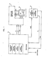
- FIG. 1 the set 10 under test and adjustment is connected to a robot and test stand unit 11.
- Unit 11 is provided with n tools t, -t n illustrated - schematically.
- these tools are screw drivers, each of which engages one potentiometer or other adjustable circuit element on the monitor and in response to control signals will perform a rotational adjustment in one of two directions, i.e., increase or decrease the potentiometer resistance depending on the direction chosen.
- the unit 11 provides power to the monitor 10 and video and control signals which it receives from a control processor 12.
- the processor 12 is of conventional design and any genera! purpose digital processor may be utilized to perform the functions described provided the unit has sufficient memory and computational power.
- the processor has stored in memory (which may include disk storage) image information which is applied to the unit 11 and thence to the monitor 10 via cable lo.
- the particular image selected is controlled by a test process program also stored in the computer memory.
- a test process program also stored in the computer memory.
- only those program steps actually being executed need be stored in the computer read/write memory.
- the other steps or modules in the case of the program and images in the case of the patterns can be resident in virtual storage on the disk and accessed when and as needed.
- An image acquisition unit (IAU) 14 is positioned so as to view the monitor screen and the image displayed thereon.
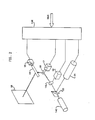
- the IAU 14 is shown in greater detail in Fig. 2 and has three controllable elements which respond to control signals from the processor 12 via cable IAUC. These signals are part of the test process and are related to the particular test and/or adjustment related to the specific image being displayed on the monitor screen.
- the IAU 14 views a small selected portion of the monitor screen and via a camera 14C shown in Fig. 2 provides a digitized image of the small portion viewed over cable li.
- the third signal element provided over the cable IAUC controls a lens system 14L in light path between the screen and the camera. The control of the lens system 14L compensates for the variable distances between the camera and the screen.
- corrections are calculated in advance for each image displayed and viewed.
- the focus correction described above will differ for each size or type screen being used. If the equipment is to be used for different monitors, the parameters for each can be stored on the disk and the proper ones selected via set-up information keyed into the computer before a production run is initiated. Alternatively, they can be dynamically selected if intermixed production is used. This will require inputting information, identifying the type of screen being adjusted and tested before the test and adjustments are initiated.
- a simple bar coded label on the monitor or its carrier with an automatic scanning device such as is commonly used in supermarkets can provide the necessary information to the processor automatically when the monitor is first brought into the test and adjustment station. Another technique which would eliminate the scanning operation is to have a pre-programmed sequence and inform the processor in advance of the types and the sequence. While this is more complicated and prone to error, it is nevertheless less expensive to implement.
- Fig. 1 illustrates an external communication line for receiving this type of control information from a central control processor, not shown, and for supplying status information relative to the adjustment and test, i.e., pass/fail information, range of adjustments, etc., all of which may be utilized by the central control processor for executing manual rework of rejected units and/or retuning other elements of the production line.
- a central control processor not shown
- status information relative to the adjustment and test i.e., pass/fail information, range of adjustments, etc.
- the digital image information and/or photo multiplier tube (PMT) output from the IAU 14 is applied to an image processing module in the processor 12 for analysis. That is what kind of distortion or deviation is present in the digitized image. Stated differently, what are the differences between the image applied to the monitor 10 and the actual image seen by the IAU camera 14L. Based on these differences, an adjustment control module provides image correction signals via a cable Ic to the robot and test stand 11. These signals, depending on the specific test and the results of the image processing, will control the robot to adjust one or more potentiometers by activating one or more tools tl --tn.
- the image processing module determines the effectiveness of the adjustment.
- the unit 10 is rejected and a message dispatched to the central control processor which will cause that monitor unit to be switched to a manual rework station further on in the assembly line conveyor.
- the digital control signals on cable IAUC are converted to analog signals by a control unit 14R and applied to a "Y" axis deflection unit 15 which deflects an elongated mirror 16 so as to view a narrow area extending horizontally from one side of the screen to the other. They are also converted to analog signals which are applied to an "X" axis deflection unit 17 which deflects a mirror 18 so as to view a narrow area on the mirror 16.
- the composite view as seen on mirror 18 is focused on the camera 14C by the lens system 14L.
- the third signal received from the processor12 adjusts the focus to take into account the physical location of the viewed area on the monitor screen.
- the monitor screen is not flat, in fact it is convex, and hence the focus varies widely as a function of the displacement of area viewed from the central region of the screen.
- the mirror acts as a point collector and as the desired path approaches the edges of the tube, the path length increases as a function of angular displacement from the normal position.
- the total deviation can be calculated in advance (or dynamically if desired) for each of the areas to be examined and applied as a focus correction factor to the lens 14L via a mechanical control unit 19 under control of the control circuit 14R which provides the necessary digital to analog conversion to provide a suitable signal for the unit 19.
- a member 20 positioned between lens 14L and camera 14C which may take the form of a mirror positioned under control of control circuit 14R can deflect the image to a photo multiplier tube 21 or allow the image to impinge directly on the photo sensitive surface of camera 14C. Alternatively, if sufficient illumination is present, a half silvered mirror may be used and the control unit 14R selects the appropriate output under control of the processor 12.
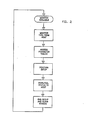
- the flow chart illustrated in Fig. 3 is a high level system chart showing the basic system steps.
- the test station first detects that a monitor is available and that the processor 12 has received and loaded the monitor type information. Next the parameter tables associated with the identified monitor are accessed. These parameter tables include the required tests, set-up sequences and tolerances, physical characteristics and distortion tables and the focus table. These elements will become more apparent in the description of Fig. 4 which follows.
- the following step is the performance of the setup which yields the pass/faii information which is sent to the central processor or host system.
- the final step is to clear the test station and await the next monitor.
- Fig. 4 is a detailed flow chart of all the detailed process steps required to practice the invention and must be viewed in conjunction with Fig. 3 which illustrates the overall process.
- the test parameters for the monitor resident in the test station are stored in processor memory and are accessed in a predetermined sequence under control of a pointer 30 illustrated schematically which may be, as is well known in computer art, a counter which is incremented, as will be described below, and points to the address in memory where the appropriate test parameters are stored.
- the first step in the process is to access the test parameter indicated by the pointer 30.
- the parameters indicate the data required and the requirements are evaluated.
- the necessary pattern (part of the test parameters) is sent to the monitor for display.
- the mirrors 16 and 18 are adjusted to view the appropriate section of the monitor screen and the lens is adjusted to focus the viewed image area defined by the angular position of mirrors 16 and 18.
- the camera is read and the image information acquired and stored in the processor memory.
- the image data is next analyzed. Following analysis a determination is made if the measured parameters fall within gross limits. Images outside of the gross limits cannot be successfully adjusted and when this is detected, a fail status message is sent to the central processor and the test and adjustment cycle is terminated. If the measured parameters are within the gross limit, they are examined to determine if they are within the tolerance band or limits.
- this phase of the test is completed except for housekeeping functions.
- the data con- ceming this test step is collected in a file which is used for off-line analysis of the system at a later time.
- the pointer 30 which points to the next step or operation is incremented.
- the next operation is examined to determine if it involves an adjustment or check, if it is one or the other, the process loops back to the first step for the next test. If not, it indicates a completion of the test and adjustment operation and the status is sent to the central processor or host.
- the step is examined to determine if a check or adjustment is called for. If the step is a check, the unit is failed and status sent to the central host. If, on the other hand, the step calls for an adjustment, the required adjustment is determined from the test parameters and the adjustment made. A loop count which is one of the gross parameters is incremented. Thus, after n unsuccessful attempted adjustments the unit will fail the gross parameter test and thus fail. The process at this, following this adjustment, loops back to recheck the measured parameters.
- the patterns ilkistrated in Figs. 5, 6 an d7 are used in conjunction with the camera or the PMT to adjust vertical parameters.
- a similar set, not shown, rotated 90° is used to adjust horizontal parameters. Since the vertical and horizontal parameter adjustments are very similar, only the vertical will be considered in detail.
- the patterns illustrated in Figs. 8, 9 and 10 are used in conjunction with the camera to check the images for a pass/fail evaluation and are not intended to be used in an adjustment operation.
- the dotted line rectangles and the circles illustrated in the illustrations of the patterns indicate various images viewed by the camera and areas viewed by the PMT, respectively.
- the pattern illustrated in Fig. 5 uses a wide solid bar 50 and two thin solid lines 51 and 52 displaced therefrom at the top of the screen. A similar pattern is displayed at the center of the screen and another pattern in which the thin lines appear above the wide solid line is displayed at the bottom of the screen. The mirrors are adjusted so that, at different times, the camera views the images formed within the rectangles illustrated in dotted line.
- the pattern illustrated in Fig. 6 includes three narrow solid lines at the top center and bottom of the screen. The mirrors are adjusted to cause the PMT to view, at different times, the screen areas identified by the circles 54.
- the pattern illustrated in Fig. 7 is a series of equidistant parallel narrow solid lines extending from the top to the bottom of the screen. Again the dotted line rectangle indicates an image viewed by the camera.
- Figs. 8, 9 and 10 are self-explanatory and illustrate patterns which can be used to check:
- the pattern illustrated in Fig. 5 consists of three copies of a basic pattern which includes a fixed solid line, called a primary region, a thin solid line spaced therefrom called a secondary region, and a second thin solid line called a tertiary region.
- This pattern is replicated three times in Fig. 5 but inverted at the bottom of the screen.
- the thickness of the bar and the spacing of the thin region is derived empirically from a consideration of the particular monitor characteristics; typically the primary region is one character block thick in the instance of a monitor.
- the camera is focused on an area of approximately 1 "xt". However, in a model which was constructed an area 1 x x 0.8" was used, rather than an absolute square. If the monitor parameter being inspected or adjusted is correct, that is, within specification, the primary region would lie in the center of the area viewed by the camera. Depending on whether a primary region, a secondary region or a tertiary region or nothing is viewed by the camera, different actions are taken and will be described below.
- the system attempts to center it using a centroid offset technique. If a secondary or tertiary region is found, the direction of the offset is known and the centroid offset for this region can be calculated. Once calculated, the adjustment is applied in an attempt to bring the primary region to its nominal position. In those instances where no regions are found within the area viewed, the direction of the offset is known.
- the relevant potentiometer or adjusting device is turned a default amount which has been empirically derived and the area re-inspected.
- the size of the potentiometer or circuit adjustment is determined from empirically derived sensitivities of the front of screen effect to circuit control rotation and the centroid offsets derived therefrom. Areas are used to distinguish regions from each other and region centroids are used to determine how far from normal a parameter is.
- Fig. 11 illustrates twelve different camera images which can result from viewing the pattern illustrated in Fig. 5. These have been labeled EO to E4 and AO-A6. In these images the dashed lines indicate invalid data, that is, the bar or line is not fully contained (in the illustrated case) vertically within the image area.
- the twelve images illustrated in Fig. 11 are grouped into two groups.
- the E group labeled EO through E4 and the A group labeled AO-A6 -in general it is possible to exit from an adjustment if one of the E group of images has been acquired, processed, and the bar satisfies certain conditions. This occurs usually when the EO image has been acquired. On the other hand, if any of the A group images have been acquired, an adjustment is either required or a fail condition has occurred.
- the pattern illustrated in Fig. 5 includes as previously described a thick bar and two thin lines spaced therefrom.
- the thick bar in the discussion which follows will be identified as a primary region.
- the immediately adjacent thin line, a secondary region, and the thin line furthest removed from the bar is a tertiary region.
- each of the three segments illustrated in Fig. 5 includes the primary, secondary and tertiary region.
- the secondary region With respect to images, A0, A2, A3 and A5, the secondary region has been identified with certainty. The offset of the secondary region from its nominal position can thus be determined and a compensating adjustment made or a fail/pass decision can be made if a correction is not effective.
- the objective when performing an adjustment is to adjust specific parameters of the primary region. There may also be conditions with respect to the secondary and tertiary regions. These conditions generally involve their absence.
- the parameter of the primary region which is the significant parameter is the position or centroid of the primary region.
- the primary objective in processing the E group images is to center the primary region by determining the centroid of the acquired region and its offset from the nominal or centered position, then performing a physical adjustment via the robot to center the primary region within the viewed area of the image.
- the first view is that the parameter is correctly adjusted. This corresponds to a sub-set of the E group of images in which the primary, secondary and tertiary regions satisfy all requirements for that parameter. In most instances this is achieved when the image EO has been acquired and the primary region has appropriate or correct characteristics.
- the second state involves where the parameter is not properly adjusted and requires adjustment or setup. This state corresponds to any of the eight groups of images which have been acquired. It also corresponds to any of the E group of images in which the primary, secondary or tertiary regions do not satisfy the requirements of the specification.
- the third state is where the parameter is in adjustment or has been properly set up but has interaction. This state corresponds to the condition where an adjustment is being performed which has an effect on the state of another parameter.
- Examples are those of height and vertical linearity. When both of these parameters are correctly adjusted, or set up, an EO type image with conditions on the primary region is expected. However, in order to successfully decouple the adjustments, linearity must be adjusted first. The state of the height parameter is therefore a variable. This may be translated into the condition that when setting up linearity the only predictable parameter is the position of the primary region, thus no constraints should be placed on the secondary and tertiary regions.
- Adjustment techniques based on the PMT output are useful for the parameters which include width, horizontal linearity or altematively horizontal centering, east/west pincushioning, height, vertical linearity or alternatively vertical centering and north/south pincushioning.
- the adjustment process is considered a closed loop with continuous feedback. That is, the output of the PMT is not a sampled output. This eliminates the need for iterations in setting up the parameter.
- This technique is tolerant of manufacturing errors, thus if potentiometers of incorrect value have been inserted in the particular monitor under test, and the correct front of screen parameters are still achievable, the technique will work with very little cycle time impact.
- the technique does not require analysis of large amounts of data such as are contained in an image in order to verify that an adjustment is being performed correctly; therefore, cycle time is essentially independent of the preset of the circuit elements.
- the adjustment direction must be known. This direction may be derived from the previously described images. Therefore, the potentiometer or circuit element can be turned in the correct direction to achieve adjustment.
- the photomultiplier tube must be able to sample a spot having a maximum diameter of 1.0 millimeters at any desired place on the face of the monitor. The structure described is fully capable of accomplishing this.
- the adjustment technique involves focusing the photomultiplier tube on the monitor screen at a specific point for a specific parameter adjustment, displaying a line such as those illustrated in Fig. 6 on the monitor, and turning the relevant circuit element until the line lies in the field of view of the photomultiplier tube.
- the sequence is as follows: (1) The pattern shown in Fig. 6 is displayed on the monitor. (2) The photomultiplier tube is pointed at and focused on one of the points indicated on the screen for a particular adjustment. (3) The photomultiplier tube output is sensed to detect the presence of light on the sensor, the relevant circuit element or potentiometer is turned to effect the adjustment and (5) when the photomultiplier tube output fires the potentiometer is no longer turned and the adjustment has been completed.
- a camera-based technique may be used to check the parameter after adjustment.
- the pattern illustrated in Fig. 7 may be utilized for adjusting the linearity of the monitor under adjustment and test and the image provided by the camera when viewing the pattern of Fig. 7 is illustrated in Fig. 12.
- the linearity potentiometer is adjusted until the distance between any of the three lines illustrated in Fig. 12 is within linearity specifications and larger than an empirically derived minimum.
- the pattern and line spacings are derived from considerations of the adjustment characteristics of each monitor type.
- the direction of the adjustment is derived from a comparison of the distances A and B identified in Fig.12. If A is larger than B, then the adjustment is in one direction. If B is larger than A, the adjustment is in the opposite direction.
- the size of the adjustment is derived from a consideration of the ratio of A and B.
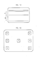
- Fig. 8 The pattern illustrated in Fig. 8 has several uses. The different areas viewed are identified by numerals in Fig. 13 while Fig. 14 illustrates the use of the patterns shown in Figs. 9 and 10. All of these are used for checking the monitor to determine whether or not the image quality meets the specifications set for a particular monitor.
- the patterns and images are used in the following way.
- the first check utilizes the images illustrated in Fig. 13.
- the first parameter checked is image tilt. This utilizes images number 3 and 4 and determines the centroid offset in one axis and hence the angle of tilt.
- the check for trapezoidal distortion uses images 1, 2, 5 and 6 and measures the centroid of the illuminated area to determine trapezoidal distortion.
- parallelism is checked by using images 1, 2, 5 and 6.
- Centering of the images is checked by using image number 7 and computes the XY centroid offset of the illuminated area.
- Convergence of the color images is also checked by using some or all of the images available. This check requires the pattern being displayed sequentially in each of the three primary colors, then the centroids of each of the color images are compared for deviation.
- a second set of checks utilizes the images illustrated in Fig. 14. These images are numbered 1-15 and one of the images in the upper left-hand corner bears two numbers. Images 1-10 are acquired when the pattern illustrated in Fig. 9 is displayed and images 11-15 are acquired when the pattern illustrated in Fig. 10 is displayed.
- North/south pincushioning check uses images 1, 5 and 10.
- the offset between the centroids of these images in one axis indicates the amount of pincushioning present in the north/south direction.
- Row straightness uses images 1-10. This test utilizes the deviation of the centroids of the images in the range of 1-10.
- Images 11, 13 and 15 are used to check east/west pincushioning and the offset between the centroids of these images in one axis indicates the amount of pincushioning present in the east/west direction.
- Column straightness is checked by using images 11-15. This check is very much similar to that used for row straightness, described above.
- the order in which the front of screen adjustments occur may differ slightly from one monitor or TV set to another. However, the following sequence has been found to be particularly useful: (1) preset contrast, (2) set brightness, (3) set horizontal centering, (4) set vertical parameters, (4A) linearity, - (4B) centering, (4C) height, (5) set horizontal parameters, (5A) width, (5B) pincushioning, (6) set brightness, (7) check parameters.
- the checks may be performed in any sequence.
Landscapes
- Engineering & Computer Science (AREA)
- Health & Medical Sciences (AREA)
- Biomedical Technology (AREA)
- General Health & Medical Sciences (AREA)
- Multimedia (AREA)
- Signal Processing (AREA)
- Testing, Inspecting, Measuring Of Stereoscopic Televisions And Televisions (AREA)
- Details Of Television Scanning (AREA)
Applications Claiming Priority (2)
| Application Number | Priority Date | Filing Date | Title |
|---|---|---|---|
| US06/740,376 US4654706A (en) | 1985-06-03 | 1985-06-03 | Automatic front of screen adjustment, testing system and method |
| US740376 | 1985-06-03 |
Publications (3)
| Publication Number | Publication Date |
|---|---|
| EP0204112A2 true EP0204112A2 (de) | 1986-12-10 |
| EP0204112A3 EP0204112A3 (en) | 1988-07-27 |
| EP0204112B1 EP0204112B1 (de) | 1992-11-11 |
Family
ID=24976254
Family Applications (1)
| Application Number | Title | Priority Date | Filing Date |
|---|---|---|---|
| EP86105145A Expired EP0204112B1 (de) | 1985-06-03 | 1986-04-15 | Verfahren und System zur automatischen Einstellung und Prüfung der Vorderseite eines Bildschirmes |
Country Status (4)
| Country | Link |
|---|---|
| US (1) | US4654706A (de) |
| EP (1) | EP0204112B1 (de) |
| JP (1) | JPS61278275A (de) |
| DE (1) | DE3687086T2 (de) |
Cited By (6)
| Publication number | Priority date | Publication date | Assignee | Title |
|---|---|---|---|---|
| GB2233866A (en) * | 1989-05-10 | 1991-01-16 | Samsung Electronics Co Ltd | Alignment of a computer controlled television |
| EP0453665A1 (de) * | 1990-04-23 | 1991-10-30 | International Business Machines Corporation | Apparat zum Abgleich der Bildgeometrie von Bildwiedergabegeräten mit einer Kathodenstrahlröhre |
| EP0458299A3 (en) * | 1990-05-23 | 1992-09-02 | Matsushita Electric Industrial Co., Ltd. | Automatic adjusting apparatus for equipment |
| EP0509129A3 (en) * | 1991-04-18 | 1993-01-20 | Grundig E.M.V. Elektro-Mechanische Versuchsanstalt Max Grundig Hollaend. Stiftung & Co. Kg. | Device for automatically adjusting and testing functions of colour component modules |
| WO2007014681A1 (en) * | 2005-08-01 | 2007-02-08 | Barco N.V. | Method and device for improved display standard conformance |
| DE102010003608A1 (de) | 2010-03-19 | 2011-11-17 | Robert Bosch Gmbh | Vorrichtung und Verfahren zur Charakterisierung eines auslenkbaren Mikrospiegels |
Families Citing this family (26)
| Publication number | Priority date | Publication date | Assignee | Title |
|---|---|---|---|---|
| US5267038A (en) * | 1988-12-30 | 1993-11-30 | Fister Michael L | Synthetic aperture video photometer system |
| US5146411A (en) * | 1990-05-29 | 1992-09-08 | International Business Machines Corporation | Computer-aided process for placement of crt trim magnets |
| JP3264919B2 (ja) * | 1990-07-23 | 2002-03-11 | 松下電器産業株式会社 | テレビジョン受信機 |
| GB9022710D0 (en) * | 1990-10-18 | 1990-11-28 | Crosfield Electronics Ltd | Methods and apparatus for testing image processing apparatus |
| KR940004058B1 (ko) * | 1992-02-20 | 1994-05-11 | 삼성전자 주식회사 | 인쇄배선판의 파형조정 및 동작검사장치 |
| JP3297950B2 (ja) * | 1993-07-13 | 2002-07-02 | シャープ株式会社 | 平面型表示パネル検査装置 |
| US6147669A (en) * | 1993-10-08 | 2000-11-14 | Sony Corporation | Method and apparatus for communicating status and control information between a processor and a display device |
| US5602932A (en) * | 1994-03-04 | 1997-02-11 | International Business Machines Corporation | Photodetector array based image analysis apparatus |
| US5504521A (en) * | 1994-06-13 | 1996-04-02 | Display Laboratories, Inc. | Method and apparatus for making corrections in a video monitor during horizontal scan |
| US6052146A (en) * | 1994-06-13 | 2000-04-18 | Display Laboratories, Inc. | Alignment of a video monitor using an on-screen display chip and a gain matrix table |
| US5510833A (en) * | 1994-06-13 | 1996-04-23 | Display Laboratories Inc. | Method and apparatus for transforming coordinate systems in an automated video monitor alignment system |
| JPH0897975A (ja) * | 1994-09-21 | 1996-04-12 | Minolta Co Ltd | 画像読み取り装置 |
| KR0127764B1 (ko) * | 1994-11-30 | 1997-12-29 | 김광호 | 캠코더의 특성조정장치 및 그 조정방법 |
| US5644757A (en) * | 1995-06-12 | 1997-07-01 | United Microelectronics Corporation | Apparatus for storing data into a digital-to-analog converter built-in to a microcontroller |
| US5739870A (en) * | 1996-03-11 | 1998-04-14 | Display Laboratories, Inc. | Math engine for generating font gradients |
| US6014168A (en) * | 1996-04-26 | 2000-01-11 | Display Laboratories, Inc. | Screen mapping of a cathode ray tube |
| US5896170A (en) * | 1996-07-02 | 1999-04-20 | Display Laboratories, Inc. | Dynamic alignment of cathode ray tube rasters |
| US6285397B1 (en) | 1997-01-16 | 2001-09-04 | Display Laboratories, Inc. | Alignment of cathode ray tube video displays using a host computer processor |
| US6437829B1 (en) | 1997-01-16 | 2002-08-20 | Display Laboratories, Inc. | Alignment of cathode ray tube displays using a video graphics controller |
| KR100257826B1 (ko) * | 1997-06-09 | 2000-07-01 | 윤종용 | 영상표시장치의 기울기 조정 방법 및 장치 |
| US6281950B1 (en) | 1997-06-16 | 2001-08-28 | Display Laboratories, Inc. | High speed digital zone control |
| US6177955B1 (en) * | 1997-10-09 | 2001-01-23 | Westar Corporation | Visual display inspection system |
| JP4550241B2 (ja) * | 2000-08-22 | 2010-09-22 | アイホン株式会社 | テレビインターホン装置 |
| JP2002142236A (ja) | 2000-11-01 | 2002-05-17 | Funai Electric Co Ltd | テレビジョンセット調整システム |
| JP2002158946A (ja) * | 2000-11-20 | 2002-05-31 | Seiko Epson Corp | プロジェクタおよび画像歪補正方法 |
| US7170550B2 (en) * | 2003-07-03 | 2007-01-30 | Sony Corporation | Television data management system |
Family Cites Families (15)
| Publication number | Priority date | Publication date | Assignee | Title |
|---|---|---|---|---|
| US3962722A (en) * | 1974-11-27 | 1976-06-08 | Zenith Radio Corporation | Color television setup apparatus and method |
| US4123775A (en) * | 1977-05-02 | 1978-10-31 | The Magnavox Company | Apparatus and method for adjusting the color temperature of a television receiver |
| JPS53144220A (en) * | 1977-05-23 | 1978-12-15 | Hitachi Ltd | Automatic adjuster for color purity of color television |
| JPS5516507A (en) * | 1978-07-20 | 1980-02-05 | Hitachi Ltd | Detector for vertical center position on television picture screen |
| US4277797A (en) * | 1979-03-19 | 1981-07-07 | Siemens Aktiengesellschaft | Color television receiver having an automatic adjustment system and a process for adjusting the receiver |
| NL7903468A (nl) * | 1979-05-03 | 1980-11-05 | Philips Nv | Inrichting voor het meten en werkwijzen voor het meten en instellen van de convergentie van de elektronen- bundels in kleurenbeeldbuizen. |
| DE3106545A1 (de) * | 1980-03-06 | 1982-02-04 | Smiths Industries Ltd., London | Verfahren zum bestimmen der anordnung einer anzeige in einer anzeigeflaeche |
| US4387394A (en) * | 1980-12-31 | 1983-06-07 | Rca Corporation | Sensing focus of a color kinescope |
| FR2523791B1 (fr) * | 1982-03-19 | 1985-01-04 | Thomson Csf | Dispositif et appareil de test d'equipements electroniques notamment de television |
| JPS594383A (ja) * | 1982-06-30 | 1984-01-11 | Fujitsu Ltd | Crt画面品質検査方式 |
| JPS59112772A (ja) * | 1982-12-20 | 1984-06-29 | Toshiba Corp | カラ−ブラウン管の画像歪測定方法及び装置 |
| JPS59156078A (ja) * | 1983-02-25 | 1984-09-05 | Toshiba Corp | カラ−受像管の表示状態検査方法 |
| US4533950A (en) * | 1983-03-23 | 1985-08-06 | Visual Information Institute, Inc. | Method of testing the linearity of a raster scan |
| US4536792A (en) * | 1983-11-23 | 1985-08-20 | Visual Information Institute, Inc. | Method and apparatus for testing a CRT display under beam duty cycle variation |
| US4568975A (en) * | 1984-08-02 | 1986-02-04 | Visual Information Institute, Inc. | Method for measuring the gray scale characteristics of a CRT display |
-
1985
- 1985-06-03 US US06/740,376 patent/US4654706A/en not_active Expired - Fee Related
-
1986
- 1986-03-03 JP JP61044279A patent/JPS61278275A/ja active Pending
- 1986-04-15 DE DE8686105145T patent/DE3687086T2/de not_active Expired - Fee Related
- 1986-04-15 EP EP86105145A patent/EP0204112B1/de not_active Expired
Cited By (9)
| Publication number | Priority date | Publication date | Assignee | Title |
|---|---|---|---|---|
| GB2233866A (en) * | 1989-05-10 | 1991-01-16 | Samsung Electronics Co Ltd | Alignment of a computer controlled television |
| EP0453665A1 (de) * | 1990-04-23 | 1991-10-30 | International Business Machines Corporation | Apparat zum Abgleich der Bildgeometrie von Bildwiedergabegeräten mit einer Kathodenstrahlröhre |
| EP0458299A3 (en) * | 1990-05-23 | 1992-09-02 | Matsushita Electric Industrial Co., Ltd. | Automatic adjusting apparatus for equipment |
| US5220496A (en) * | 1990-05-23 | 1993-06-15 | Matsushita Electric Industrial Co., Ltd. | Automatic adjusting apparatus for equipment |
| EP0509129A3 (en) * | 1991-04-18 | 1993-01-20 | Grundig E.M.V. Elektro-Mechanische Versuchsanstalt Max Grundig Hollaend. Stiftung & Co. Kg. | Device for automatically adjusting and testing functions of colour component modules |
| WO2007014681A1 (en) * | 2005-08-01 | 2007-02-08 | Barco N.V. | Method and device for improved display standard conformance |
| US9368057B2 (en) | 2005-08-01 | 2016-06-14 | Barco, N.V. | Method and device for improved display standard conformance |
| DE102010003608A1 (de) | 2010-03-19 | 2011-11-17 | Robert Bosch Gmbh | Vorrichtung und Verfahren zur Charakterisierung eines auslenkbaren Mikrospiegels |
| DE102010003608B4 (de) | 2010-03-19 | 2019-04-04 | Robert Bosch Gmbh | Vorrichtung und Verfahren zur Charakterisierung eines auslenkbaren Mikrospiegels |
Also Published As
| Publication number | Publication date |
|---|---|
| EP0204112A3 (en) | 1988-07-27 |
| EP0204112B1 (de) | 1992-11-11 |
| DE3687086D1 (de) | 1992-12-17 |
| US4654706A (en) | 1987-03-31 |
| DE3687086T2 (de) | 1993-05-19 |
| JPS61278275A (ja) | 1986-12-09 |
Similar Documents
| Publication | Publication Date | Title |
|---|---|---|
| US4654706A (en) | Automatic front of screen adjustment, testing system and method | |
| US4999703A (en) | Automatic image correction method and apparatus for projectors utilizing cathode ray tubes | |
| US7182464B2 (en) | Projector with adjustably positioned image plate | |
| EP0518473B1 (de) | System zum Zuschneiden von Kleidungsstücken mit rechnergestützter Ausrichtung von Zuschneidermustern | |
| AU692863B2 (en) | Automated image quality control | |
| JP2505535B2 (ja) | 見当ずれ測定装置,見当マ―クおよび表面印刷と両面印刷を判定する方法 | |
| US5969756A (en) | Test and alignment system for electronic display devices and test fixture for same | |
| EP0600742B1 (de) | Sensor-Vorrichtung und -Verfahren mit Unterdrückung von Nichtuniformitäten und gleichzeitiger Erhaltung von Bildinhalten | |
| US5541856A (en) | X-ray inspection system | |
| CA2191608A1 (en) | Method and apparatus for transforming coordinate systems in an automated video monitor alignment system | |
| US4648048A (en) | Apparatus for determining and evaluating color measurement strips on a printed sheet | |
| EP0728399B1 (de) | Verfahren und vorrichtung zur prüfung von leiterplatten mit verschiedenen vergrösserungen | |
| NO834370L (no) | Datainnsamlingssystem for videofremvisning i storformat | |
| US5392360A (en) | Method and apparatus for inspection of matched substrate heatsink and hat assemblies | |
| KR20090059032A (ko) | 디스플레이 패널의 검사 방법 및 검사 장치 | |
| US12044634B2 (en) | X-ray automated calibration and monitoring | |
| US4232335A (en) | Numerical control tape preparation machine | |
| US5188110A (en) | Method and apparatus for setting multi-slice imaging conditions in computed tomographic imaging systems | |
| EP0508361B1 (de) | Bildlesegerät | |
| EP0020934B1 (de) | Ausrichten oder Korrigieren von Energiestrahlwiedergabevorrichtungen | |
| US7536053B2 (en) | Method and apparatus for the correction of nonlinear field of view distortion of a digital imaging system | |
| US4794462A (en) | Method and system for patching an original at a desired angular orientation on a scanner input drum or an original patching sheet and extracting original trimming data | |
| GB2190743A (en) | Compensating for misalignment in the comparison of patterns | |
| CN118118750A (zh) | 摄像设备的调焦方法、装置、电子设备、系统和存储介质 | |
| JPH08320252A (ja) | 赤外線センサの動作試験装置 |
Legal Events
| Date | Code | Title | Description |
|---|---|---|---|
| PUAI | Public reference made under article 153(3) epc to a published international application that has entered the european phase |
Free format text: ORIGINAL CODE: 0009012 |
|
| AK | Designated contracting states |
Kind code of ref document: A2 Designated state(s): DE FR GB |
|
| 17P | Request for examination filed |
Effective date: 19870422 |
|
| PUAL | Search report despatched |
Free format text: ORIGINAL CODE: 0009013 |
|
| AK | Designated contracting states |
Kind code of ref document: A3 Designated state(s): DE FR GB |
|
| 17Q | First examination report despatched |
Effective date: 19900516 |
|
| GRAA | (expected) grant |
Free format text: ORIGINAL CODE: 0009210 |
|
| AK | Designated contracting states |
Kind code of ref document: B1 Designated state(s): DE FR GB |
|
| REF | Corresponds to: |
Ref document number: 3687086 Country of ref document: DE Date of ref document: 19921217 |
|
| ET | Fr: translation filed | ||
| PGFP | Annual fee paid to national office [announced via postgrant information from national office to epo] |
Ref country code: GB Payment date: 19930324 Year of fee payment: 8 |
|
| PGFP | Annual fee paid to national office [announced via postgrant information from national office to epo] |
Ref country code: FR Payment date: 19930330 Year of fee payment: 8 |
|
| PGFP | Annual fee paid to national office [announced via postgrant information from national office to epo] |
Ref country code: DE Payment date: 19930428 Year of fee payment: 8 |
|
| PLBE | No opposition filed within time limit |
Free format text: ORIGINAL CODE: 0009261 |
|
| STAA | Information on the status of an ep patent application or granted ep patent |
Free format text: STATUS: NO OPPOSITION FILED WITHIN TIME LIMIT |
|
| 26N | No opposition filed | ||
| PG25 | Lapsed in a contracting state [announced via postgrant information from national office to epo] |
Ref country code: GB Effective date: 19940415 |
|
| GBPC | Gb: european patent ceased through non-payment of renewal fee |
Effective date: 19940415 |
|
| PG25 | Lapsed in a contracting state [announced via postgrant information from national office to epo] |
Ref country code: FR Effective date: 19941229 |
|
| PG25 | Lapsed in a contracting state [announced via postgrant information from national office to epo] |
Ref country code: DE Effective date: 19950103 |
|
| REG | Reference to a national code |
Ref country code: FR Ref legal event code: ST |