EP0204126B1 - Electrode pour électrolyse à membrane - Google Patents
Electrode pour électrolyse à membrane Download PDFInfo
- Publication number
- EP0204126B1 EP0204126B1 EP86105660A EP86105660A EP0204126B1 EP 0204126 B1 EP0204126 B1 EP 0204126B1 EP 86105660 A EP86105660 A EP 86105660A EP 86105660 A EP86105660 A EP 86105660A EP 0204126 B1 EP0204126 B1 EP 0204126B1
- Authority
- EP
- European Patent Office
- Prior art keywords
- electrode according
- recesses
- membrane
- electrode
- lamellas
- Prior art date
- Legal status (The legal status is an assumption and is not a legal conclusion. Google has not performed a legal analysis and makes no representation as to the accuracy of the status listed.)
- Expired
Links
Images


Classifications
-
- C—CHEMISTRY; METALLURGY
- C25—ELECTROLYTIC OR ELECTROPHORETIC PROCESSES; APPARATUS THEREFOR
- C25B—ELECTROLYTIC OR ELECTROPHORETIC PROCESSES FOR THE PRODUCTION OF COMPOUNDS OR NON-METALS; APPARATUS THEREFOR
- C25B11/00—Electrodes; Manufacture thereof not otherwise provided for
- C25B11/02—Electrodes; Manufacture thereof not otherwise provided for characterised by shape or form
Definitions
- the invention relates to an electrode for membrane electrolysis in preferably vertical electrolysis cells, with an electrode body which is formed from a number of parallel, spaced-apart lamellae and whose surface is at least partially provided with an electrocatalytically active coating.
- Coated electrodes of this type are used in particular as anodes in electrolysis devices which operate according to the membrane cell method.
- membrane cell technology an ion exchange membrane is placed between the cathode and the anode. This membrane is impermeable to liquids, but certain ions can diffuse through it.
- the membrane process for the production of chlorine, sodium or potassium hydroxide solution and hydrogen is becoming increasingly important.
- Membrane cell systems in particular have a pronounced dependency of the specific energy consumption on the current density. If one can be satisfied with the relatively inexpensive diaphragm cells, given their high k-value of 0.37-0.50 V xm 2 / kA, with relatively low current densities in the range of 2-3 kA / m2, the more expensive membrane cells, on the other hand, require much higher ones Current densities. Current densities of 3 to 6 kA / m 2 and even up to 10 kAlm 2 are aimed for in order to enable economical operation.
- DE-A 3 223 701 attempts to ensure a secure plane parallelism of the electrode surfaces and an energetically favorable minimum electrode spacing in that one of the two electrodes can be displaced by spring elements.
- the arrangement proposed there requires too additional constructive elements; a decrease in their spring properties or even jamming of the moving parts can easily lead to failure of the electrolytic cell.
- the membrane is pressed against one of the flat electrodes by means of a special support structure. Although the distance between the membrane and the electrode becomes zero, one side of the membrane is completely covered by the electrode lying on it. The membrane is only in contact with the electrolyte on one side; the supply of ions from the electrolyte is therefore difficult. Furthermore, the resulting gas bubbles can only escape to one side.
- the additional support structure makes the electrolysis cell considerably more expensive. In addition, special precautions must be taken so that the sensitive membrane is not damaged by the resilient elements of the support structure.
- the bipolar electrolysis cell described in DE-C 2 545 339 also has a flat electrode on which the membrane bears without a gap.
- the resulting poor gas discharge should be improved by gaps or openings in the electrode.
- the escape of gas bubbles upwards is made considerably more difficult by such a flat electrode with an overlying membrane.
- large parts of the membrane are also excluded from the electrolyte supply.
- EP-A 0 095 039 proposes an electrode with a grid-like structure.
- the membrane is clamped between the bars of the electrodes assigned in pairs. The result of this is that the thin membrane comes to lie in a wave shape between the electrodes, which leads to a completely inhomogeneous current density distribution.
- the membrane resting on both the anode and the cathode, relatively large parts of the membrane do not come into contact with the electrolyte here either.
- gas bubbles can escape on both sides of the membrane, the essentially horizontal arrangement of the lattice elements prevents free gas removal from the cells.
- the voltage coefficient of such membrane electrolysis cells is unsatisfactory.
- an electrode which is in principle planar is also proposed. Special elevations or depressions bent out of the surface are intended to reduce the current requirement of this electrode.
- This electrode is electrocatalytically coated on its entire surface. An adjacent ion exchanger membrane would therefore be damaged on the contact surfaces as a result of current peaks occurring there if one wanted to achieve the high current densities mentioned at the beginning with such an electrode.
- a large proportion of the surface of the membrane on the electrode side is covered, which leads to an undersupply of electrolyte. Since the very thin, flat membrane rests on curved surfaces, there are also high mechanical loads locally, which can damage the sensitive and expensive membrane. In addition, gas bubbles easily settle in the round indentations, which can seriously disrupt the transport of electricity to the electrode.
- This electrode is therefore not very suitable for the construction of a membrane electrolysis cell with a good voltage coefficient, which can be operated at high current densities.
- US-A 4 013 537 relates to a membrane electrolysis cell. It is equipped with vertically running electrode bodies, each of which has strips running vertically on the membrane side.
- FR-A 2 244 836 also discloses a relevant membrane electrolysis cell. According to one exemplary embodiment, it comprises U-shaped electrode lamellae, the legs of which are connected with webs which, on the one hand, serve for welding or soldering to a plate and, on the other hand, connect and reinforce the lamellae.
- the object of the invention is therefore to provide an electrode which, while avoiding the disadvantages described, is suitable for the construction of a membrane electrolysis cell which can be operated safely at high current densities and which has a good voltage coefficient and which, moreover, can be produced simply and therefore inexpensively.
- an electrode for membrane electrolysis with an electrode body, the surface of which is at least partially provided with an electrocatalytically active coating, in that the electrode body is formed from a number of parallel, spaced-apart lamellae that the lamellae have a plurality of recesses on their end faces facing the membrane, and that the end faces of the webs located between these recesses are not actively electrocatalytically coated.
- the electrode designed according to the invention is excellently suitable for the application of an ion exchange membrane.
- the membrane lies flat on the end faces of the webs located between the recesses, so that the effective distance between the membrane and the electrode is zero. This allows the construction of a so-called "zero gap cell". Since the end faces of the webs, on which the membrane rests, are uncoated, no current peaks can occur there. An overload of the membrane caused by this is therefore largely excluded. The entire surface of the membrane is leaned against the electrode. In contrast to rigid membrane clamping, this allows the separator to work freely, for example if the electrolyte level in the cell is too low.
- the membrane is largely free in the cell space and only to a very small extent from the bars of the electrical system the body is covered. It is therefore excellently supplied with electrolyte from all sides, which ensures the necessary replenishment of ions. Local polarizations that could damage the membrane are avoided. The loss of electrocatalytically active electrode area through the uncoated end faces of the webs is small, so that high current densities can nevertheless be achieved with the electrode according to the invention.
- the proposed lamellar structure of the electrode in conjunction with the large number of recesses on the end faces facing the membrane further enables gas bubbles to escape rapidly.
- the proposed electrode geometry thus allows the construction of high-quality membrane electrolysis cells with the desired low voltage coefficient.
- a vertical arrangement of the fins in the vertical cells promotes the flow of electrolyte through the cell from bottom to top.
- a vertical cell structure is also advantageous with regard to the gas bubble effect which counteracts the high current densities.
- the lamellae forming the electrode body are expediently designed as rectangular, flat plates. Such plates are easy to manufacture; in addition, the recesses according to the invention can be easily made.
- the recesses of two adjacent slats are arranged offset from one another. This allows a particularly uniform support of the membrane on top.
- the recesses of all lamellae expediently have the same dimensions and are arranged regularly. In this way, a particularly uniform current density distribution is achieved.
- a particularly uniform, mechanical and electrical stress on the adjacent membrane results when the recesses of two adjacent lamellae are offset from one another by half the width of a recess.
- a flat design of the end faces of the webs allows the membrane to lie flat. This can then shift slightly with respect to the electrode, for example in the event of changes in length due to the absorption of liquid or due to temperature fluctuations. Slats with flat end faces can also be produced particularly easily and inexpensively.
- the passivation of the web surfaces can namely be accomplished by simply grinding the electrocatalytically active coating using a surface grinder.
- Rectangular recesses are particularly easy to work into the slats.
- the bottoms of such recesses are parallel to the membrane and thus also to the current direction. This leads to the largest possible, effective, electrocatalytically active surface of the electrode according to the invention.
- other, for example round, shapes of the recesses are also conceivable.
- edges between the bottoms and the side surfaces of the recesses and the edges between the recesses and the end surfaces of the webs can be rounded.
- the edges between the end faces of the webs and the side faces of the slats can also be rounded.
- the width of the recesses corresponds approximately to the width of the webs. This dimensioning represents a good compromise between the demands for the best possible support of the membrane and a simultaneous, as unimpeded supply of electrolyte as possible.
- the depth of the recesses is less than their width and the distance between two adjacent lamellae approximately corresponds to the width of the recesses.
- the width of the recesses and the width of the webs are each a few millimeters.
- a depth of the recesses of a few millimeters is sufficient for an adequate supply of the membrane with electrolyte. Particularly good results were achieved with recesses whose depth was between 2 and 4 mm.
- a sufficient electrolyte flow between the lamellae results with a lamella spacing of a few millimeters; in a particularly preferred embodiment, this distance is between 4 and 6 mm.
- the lamellae are electrically conductively connected to one another with a current distributor.
- a largely unimpeded flow of electrolyte results from the arrangement of a rectangular power distributor on the back of the slats.
- Electrolysis cells with electrode bodies made of valve metal, preferably made of titanium, are distinguished by a particularly high current efficiency.
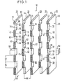
- the electrode shown in FIG. 1 has an electrode body 10 with a number of vertical, parallel, spaced-apart lamellae 20. These lamellae 20 are designed as rectangular, flat plates. On their end faces 21 they have a large number of identical recesses 30 of rectangular cross section. Between the recesses 30 there are webs 40 with flat end faces 41.
- the lamellae 20 forming the electrode body 10 are made of titanium. With the exception of the end faces 41, the lamellae 20 are provided with an electrocatalytically active coating. The edges 50 between the bottom surfaces 31 and the side surfaces 32, 33 of the recesses 30 are rounded.
- the edges 60 between the recesses 30 and the end faces 41 and the edges 70 between the end faces 41 and the side faces 23, 24 of the slats 20 are rounded.
- the width 34 of the recesses 30 corresponds to the width 42 of the webs 40.
- the depth 35 of the recesses 30 is less than their width 34; it is approximately 3 mm.
- the recesses 30 of all the slats 20 are arranged regularly.
- the recesses 30 of two adjacent slats 20 are offset from one another by exactly half the width 34.
- All slats 20 are at the same distance 80 from one another.
- the distance 80 is approximately 5 mm.
- the lamellae 20 are electrically conductively connected to one another with a current distributor 90 of rectangular cross section.
- FIG. 2 schematically shows the structure of a membrane electrolysis cell using the electrode according to the invention shown in FIG. 1.
- the fins 20 are vertical in the cell and form the anode.
- a membrane 91 bears against the end faces 41 of the webs 40.
- the counter electrode 92 is designed as a lamellar cathode. The distance between the membrane 91 and the counter electrode 92 is a few millimeters.
- FIG. 3 shows a similar arrangement in which the electrode according to the invention is opposed by a solid sheet cathode as counter electrode 92.
- a perforated plate cathode is used as counter electrode 92.
- This design is characterized by a particularly favorable current density distribution and a good supply to the membrane 91.
- the liquid electrolyte can reach the membrane 91 unhindered through the spaces between the lamellae 20 and their recesses 30.
- the electrolyte is supplied through the holes in the counter electrode 92.
- FIG. 5 shows a membrane electrolysis cell with an electrode according to the invention as an anode and a counter electrode 92 designed as an expanded metal cathode.
- the membrane 91 is largely exposed in space. Only about 10% of the membrane 91 is covered by the end faces 41 of the webs 40. Together with the open structure of the counterelectrode 92, this provides an excellent possibility of replenishing Na + ions.
- the vertical structure of the electrolysis cell as a result of the vertical arrangement of the fins 20 allows gas bubbles which arise to escape unimpeded upwards.
Landscapes
- Chemical & Material Sciences (AREA)
- Engineering & Computer Science (AREA)
- Chemical Kinetics & Catalysis (AREA)
- Electrochemistry (AREA)
- Materials Engineering (AREA)
- Metallurgy (AREA)
- Organic Chemistry (AREA)
- Electrolytic Production Of Non-Metals, Compounds, Apparatuses Therefor (AREA)
- Electrodes For Compound Or Non-Metal Manufacture (AREA)
- Manufacture Of Macromolecular Shaped Articles (AREA)
- Electrolytic Production Of Metals (AREA)
- Separation Using Semi-Permeable Membranes (AREA)
Claims (23)
Priority Applications (1)
| Application Number | Priority Date | Filing Date | Title |
|---|---|---|---|
| AT86105660T ATE45395T1 (de) | 1985-05-31 | 1986-04-24 | Elektrode fuer die membran-elektrolyse. |
Applications Claiming Priority (2)
| Application Number | Priority Date | Filing Date | Title |
|---|---|---|---|
| DE3519573 | 1985-05-31 | ||
| DE19853519573 DE3519573A1 (de) | 1985-05-31 | 1985-05-31 | Elektrode fuer die membran-elektrolyse |
Publications (2)
| Publication Number | Publication Date |
|---|---|
| EP0204126A1 EP0204126A1 (fr) | 1986-12-10 |
| EP0204126B1 true EP0204126B1 (fr) | 1989-08-09 |
Family
ID=6272125
Family Applications (1)
| Application Number | Title | Priority Date | Filing Date |
|---|---|---|---|
| EP86105660A Expired EP0204126B1 (fr) | 1985-05-31 | 1986-04-24 | Electrode pour électrolyse à membrane |
Country Status (7)
| Country | Link |
|---|---|
| US (1) | US4695355A (fr) |
| EP (1) | EP0204126B1 (fr) |
| AT (1) | ATE45395T1 (fr) |
| CA (1) | CA1291444C (fr) |
| DE (2) | DE3519573A1 (fr) |
| HU (1) | HUT45101A (fr) |
| NO (1) | NO862167L (fr) |
Families Citing this family (18)
| Publication number | Priority date | Publication date | Assignee | Title |
|---|---|---|---|---|
| SE465966B (sv) * | 1989-07-14 | 1991-11-25 | Permascand Ab | Elektrod foer elektrolys, foerfarande foer dess framstaellning samt anvaendningen av elektroden |
| US5087344A (en) * | 1990-09-26 | 1992-02-11 | Heraeus Elektroden Gmbh | Electrolysis cell for gas-evolving electrolytic processes |
| DE4419274A1 (de) * | 1994-06-01 | 1995-12-07 | Heraeus Elektrochemie | Elektrode für Elektrolysezellen |
| JP3035483B2 (ja) * | 1995-11-27 | 2000-04-24 | スガ試験機株式会社 | 酸素・水素電解ガス発生装置 |
| DE10234806A1 (de) * | 2002-07-31 | 2004-02-19 | Bayer Ag | Elektrochemische Zelle |
| ITMI20031269A1 (it) * | 2003-06-24 | 2004-12-25 | De Nora Elettrodi Spa | Nuovo anodo espandibile per celle a diaframma. |
| WO2013036802A1 (fr) | 2011-09-07 | 2013-03-14 | 24M Technologies, Inc. | Module de batterie semi-solide fixe et son procédé de production |
| US9401501B2 (en) | 2012-05-18 | 2016-07-26 | 24M Technologies, Inc. | Electrochemical cells and methods of manufacturing the same |
| EP2772469A1 (fr) | 2013-02-27 | 2014-09-03 | Bayer Technology Services GmbH | Micro-cellules à électrodes à lamelles et leur utilisation |
| EP2913306A1 (fr) | 2014-02-27 | 2015-09-02 | Bayer Technology Services GmbH | Procédé de nettoyage d'appareils de pulvérisation de résidus de produits phytosanitaires |
| ES2975858T3 (es) | 2014-10-13 | 2024-07-16 | 24M Tech Inc | Sistemas y métodos de carga y de formación de baterías en serie |
| EP3216067B1 (fr) | 2014-11-05 | 2021-09-15 | 24m Technologies, Inc. | Cellules électrochimiques à électrodes semi-solides et leurs procédés de fabrication |
| US10115970B2 (en) | 2015-04-14 | 2018-10-30 | 24M Technologies, Inc. | Semi-solid electrodes with porous current collectors and methods of manufacture |
| EP4668405A3 (fr) | 2015-06-18 | 2026-03-25 | 24M Technologies, Inc. | Cellules de batterie à poche unique et procédés de fabrication |
| US11742525B2 (en) | 2020-02-07 | 2023-08-29 | 24M Technologies, Inc. | Divided energy electrochemical cell systems and methods of producing the same |
| US12381277B2 (en) | 2020-06-17 | 2025-08-05 | 24M Technologies, Inc. | Electrochemical cells with flame retardant mechanism and methods of producing the same |
| US12320018B2 (en) * | 2020-11-23 | 2025-06-03 | Lawrence Livermore National Security, Llc | Corrugated electrodes for electrochemical applications |
| DE102022209312A1 (de) | 2022-09-07 | 2024-03-07 | Siemens Energy Global GmbH & Co. KG | Verfahren zur Herstellung eines Verbunds von Streckgittern, Stapel von Streckgittern und Portalmaschine |
Family Cites Families (7)
| Publication number | Priority date | Publication date | Assignee | Title |
|---|---|---|---|---|
| HU144457A (fr) * | 1956-10-27 | |||
| GB1290099A (fr) * | 1969-06-25 | 1972-09-20 | ||
| US4013525A (en) * | 1973-09-24 | 1977-03-22 | Imperial Chemical Industries Limited | Electrolytic cells |
| US4036717A (en) * | 1975-12-29 | 1977-07-19 | Diamond Shamrock Corporation | Method for concentration and purification of a cell liquor in an electrolytic cell |
| US4013537A (en) * | 1976-06-07 | 1977-03-22 | The B. F. Goodrich Company | Electrolytic cell design |
| FI58656C (fi) * | 1978-06-06 | 1981-03-10 | Finnish Chemicals Oy | Elektrolyscell och saett att framstaella densamma |
| DE3170397D1 (en) * | 1980-07-30 | 1985-06-13 | Ici Plc | Electrode for use in electrolytic cell |
-
1985
- 1985-05-31 DE DE19853519573 patent/DE3519573A1/de not_active Withdrawn
-
1986
- 1986-04-24 DE DE8686105660T patent/DE3664933D1/de not_active Expired
- 1986-04-24 EP EP86105660A patent/EP0204126B1/fr not_active Expired
- 1986-04-24 AT AT86105660T patent/ATE45395T1/de active
- 1986-05-13 US US06/862,818 patent/US4695355A/en not_active Expired - Fee Related
- 1986-05-20 HU HU862130A patent/HUT45101A/hu unknown
- 1986-05-30 NO NO862167A patent/NO862167L/no unknown
- 1986-05-30 CA CA000510423A patent/CA1291444C/fr not_active Expired - Lifetime
Also Published As
| Publication number | Publication date |
|---|---|
| US4695355A (en) | 1987-09-22 |
| ATE45395T1 (de) | 1989-08-15 |
| HUT45101A (en) | 1988-05-30 |
| NO862167L (no) | 1986-12-01 |
| EP0204126A1 (fr) | 1986-12-10 |
| DE3519573A1 (de) | 1986-12-04 |
| CA1291444C (fr) | 1991-10-29 |
| DE3664933D1 (en) | 1989-09-14 |
Similar Documents
| Publication | Publication Date | Title |
|---|---|---|
| EP0204126B1 (fr) | Electrode pour électrolyse à membrane | |
| DE69015518T2 (de) | Elektrode für Elektrolyse. | |
| DE3051012C2 (fr) | ||
| EP0428171B1 (fr) | Cellule d'électrolyse pour la production de composés peroxo et perhalogénés | |
| DE2656650A1 (de) | Bipolare elektrode fuer eine elektrolysezelle | |
| CH645138A5 (de) | Elektrodenanordnung. | |
| DD154831A5 (de) | Verfahren und vorrichtung zur elektrolyse | |
| DD211130A5 (de) | Elektrodenbauteil | |
| DE2856882C2 (fr) | ||
| EP0095039B1 (fr) | Cellule d'électrolyse à membrane | |
| DE4306889C1 (de) | Elektrodenanordnung für gasbildende elektrolytische Prozesse in Membran-Zellen und deren Verwendung | |
| EP0479840B1 (fr) | Cellule electrolytique pour processus electrolytiques degageant du gaz | |
| DE69213362T2 (de) | Elektrolyseur und Herstellung davon | |
| DD204949A5 (de) | Elektrolytzelle des filterpressentyps | |
| DE3401812C2 (de) | Elektrolysezelle | |
| EP1285103B1 (fr) | Cellule electrolytique polyvalente bipolaire destinee a des charges electriques elevees | |
| EP0097991B1 (fr) | Cellule d'électrolyse à membrane avec électrodes disposées verticalement | |
| DE2923818A1 (de) | Elektrodenabteil | |
| CH654852A5 (de) | Elektrode fuer elektrolysezellen. | |
| DE4419683C2 (de) | Bipolare Filterpressenzelle für anodische Oxidationen an Platin | |
| DE19853458C2 (de) | Polymerelektrolytmembran-Elektrolysezellenmodul und Polymerelektrolytmembran-Elektrolysevorrichtung mit einem solchen Modul | |
| DE3603254A1 (de) | Elektrolysezelleneinheit | |
| DE3519272C1 (de) | Elektrodenstruktur fuer elektrochemische Zellen | |
| WO2022122080A1 (fr) | Tôle formant électrode destinée à une batterie redox et batterie redox | |
| DD285127B5 (de) | Elektrodenelement einer Elektrode fuer gasentwickelnde elektrolytische Prozesse |
Legal Events
| Date | Code | Title | Description |
|---|---|---|---|
| PUAI | Public reference made under article 153(3) epc to a published international application that has entered the european phase |
Free format text: ORIGINAL CODE: 0009012 |
|
| AK | Designated contracting states |
Kind code of ref document: A1 Designated state(s): AT BE CH DE FR GB IT LI NL SE |
|
| 17P | Request for examination filed |
Effective date: 19870312 |
|
| 17Q | First examination report despatched |
Effective date: 19880205 |
|
| GRAA | (expected) grant |
Free format text: ORIGINAL CODE: 0009210 |
|
| AK | Designated contracting states |
Kind code of ref document: B1 Designated state(s): AT BE CH DE FR GB IT LI NL SE |
|
| PG25 | Lapsed in a contracting state [announced via postgrant information from national office to epo] |
Ref country code: BE Effective date: 19890809 |
|
| REF | Corresponds to: |
Ref document number: 45395 Country of ref document: AT Date of ref document: 19890815 Kind code of ref document: T |
|
| ITF | It: translation for a ep patent filed | ||
| ET | Fr: translation filed | ||
| GBT | Gb: translation of ep patent filed (gb section 77(6)(a)/1977) | ||
| RAP2 | Party data changed (patent owner data changed or rights of a patent transferred) |
Owner name: HERAEUS ELEKTRODEN GMBH |
|
| REF | Corresponds to: |
Ref document number: 3664933 Country of ref document: DE Date of ref document: 19890914 |
|
| ET1 | Fr: translation filed ** revision of the translation of the patent or the claims | ||
| BECN | Be: change of holder's name |
Effective date: 19890809 |
|
| PG25 | Lapsed in a contracting state [announced via postgrant information from national office to epo] |
Ref country code: GB Effective date: 19900424 Ref country code: AT Effective date: 19900424 |
|
| PG25 | Lapsed in a contracting state [announced via postgrant information from national office to epo] |
Ref country code: SE Effective date: 19900425 |
|
| PG25 | Lapsed in a contracting state [announced via postgrant information from national office to epo] |
Ref country code: LI Effective date: 19900430 Ref country code: CH Effective date: 19900430 |
|
| PLBE | No opposition filed within time limit |
Free format text: ORIGINAL CODE: 0009261 |
|
| STAA | Information on the status of an ep patent application or granted ep patent |
Free format text: STATUS: NO OPPOSITION FILED WITHIN TIME LIMIT |
|
| 26N | No opposition filed | ||
| PG25 | Lapsed in a contracting state [announced via postgrant information from national office to epo] |
Ref country code: NL Effective date: 19901101 |
|
| NLV4 | Nl: lapsed or anulled due to non-payment of the annual fee | ||
| GBPC | Gb: european patent ceased through non-payment of renewal fee | ||
| PG25 | Lapsed in a contracting state [announced via postgrant information from national office to epo] |
Ref country code: FR Effective date: 19901228 |
|
| REG | Reference to a national code |
Ref country code: CH Ref legal event code: PL |
|
| PG25 | Lapsed in a contracting state [announced via postgrant information from national office to epo] |
Ref country code: DE Effective date: 19910101 |
|
| REG | Reference to a national code |
Ref country code: FR Ref legal event code: ST |
|
| EUG | Se: european patent has lapsed |
Ref document number: 86105660.4 Effective date: 19910116 |
|
| PG25 | Lapsed in a contracting state [announced via postgrant information from national office to epo] |
Ref country code: IT Free format text: LAPSE BECAUSE OF NON-PAYMENT OF DUE FEES;WARNING: LAPSES OF ITALIAN PATENTS WITH EFFECTIVE DATE BEFORE 2007 MAY HAVE OCCURRED AT ANY TIME BEFORE 2007. THE CORRECT EFFECTIVE DATE MAY BE DIFFERENT FROM THE ONE RECORDED. Effective date: 20050424 |