EP0204127A2 - Druckfester Mischer - Google Patents
Druckfester Mischer Download PDFInfo
- Publication number
- EP0204127A2 EP0204127A2 EP86105684A EP86105684A EP0204127A2 EP 0204127 A2 EP0204127 A2 EP 0204127A2 EP 86105684 A EP86105684 A EP 86105684A EP 86105684 A EP86105684 A EP 86105684A EP 0204127 A2 EP0204127 A2 EP 0204127A2
- Authority
- EP
- European Patent Office
- Prior art keywords
- pressure
- mixing
- container
- vessel
- mixing container
- Prior art date
- Legal status (The legal status is an assumption and is not a legal conclusion. Google has not performed a legal analysis and makes no representation as to the accuracy of the status listed.)
- Granted
Links
- 238000002156 mixing Methods 0.000 claims abstract description 161
- 239000000203 mixture Substances 0.000 claims description 40
- 238000007789 sealing Methods 0.000 claims description 20
- 238000011049 filling Methods 0.000 claims description 5
- 230000002745 absorbent Effects 0.000 claims description 2
- 239000002250 absorbent Substances 0.000 claims description 2
- 239000000463 material Substances 0.000 abstract description 26
- 239000007789 gas Substances 0.000 description 11
- 238000010438 heat treatment Methods 0.000 description 10
- 230000008901 benefit Effects 0.000 description 6
- 230000007246 mechanism Effects 0.000 description 6
- 238000000034 method Methods 0.000 description 6
- 239000002826 coolant Substances 0.000 description 5
- 230000008569 process Effects 0.000 description 5
- 230000001681 protective effect Effects 0.000 description 4
- 239000002904 solvent Substances 0.000 description 4
- 239000000470 constituent Substances 0.000 description 3
- 238000001816 cooling Methods 0.000 description 3
- 238000009434 installation Methods 0.000 description 3
- 239000007788 liquid Substances 0.000 description 3
- 238000012423 maintenance Methods 0.000 description 3
- 230000000694 effects Effects 0.000 description 2
- 238000001704 evaporation Methods 0.000 description 2
- 230000008020 evaporation Effects 0.000 description 2
- 230000009969 flowable effect Effects 0.000 description 2
- 238000004898 kneading Methods 0.000 description 2
- 238000004519 manufacturing process Methods 0.000 description 2
- 238000005192 partition Methods 0.000 description 2
- 238000002360 preparation method Methods 0.000 description 2
- 238000005086 pumping Methods 0.000 description 2
- 239000000126 substance Substances 0.000 description 2
- DNXHEGUUPJUMQT-CBZIJGRNSA-N Estrone Chemical compound OC1=CC=C2[C@H]3CC[C@](C)(C(CC4)=O)[C@@H]4[C@@H]3CCC2=C1 DNXHEGUUPJUMQT-CBZIJGRNSA-N 0.000 description 1
- 230000008859 change Effects 0.000 description 1
- 238000006243 chemical reaction Methods 0.000 description 1
- 230000006835 compression Effects 0.000 description 1
- 238000007906 compression Methods 0.000 description 1
- 238000011109 contamination Methods 0.000 description 1
- 239000000110 cooling liquid Substances 0.000 description 1
- 238000013016 damping Methods 0.000 description 1
- 230000001419 dependent effect Effects 0.000 description 1
- 239000000428 dust Substances 0.000 description 1
- 239000002360 explosive Substances 0.000 description 1
- 239000000945 filler Substances 0.000 description 1
- 238000005429 filling process Methods 0.000 description 1
- 238000011068 loading method Methods 0.000 description 1
- 238000010327 methods by industry Methods 0.000 description 1
- 239000003973 paint Substances 0.000 description 1
- 235000011837 pasties Nutrition 0.000 description 1
- 239000004033 plastic Substances 0.000 description 1
- 238000003825 pressing Methods 0.000 description 1
- 238000007639 printing Methods 0.000 description 1
- 230000001105 regulatory effect Effects 0.000 description 1
- 230000008439 repair process Effects 0.000 description 1
- 239000004576 sand Substances 0.000 description 1
- 238000000926 separation method Methods 0.000 description 1
- 239000007787 solid Substances 0.000 description 1
- 238000003756 stirring Methods 0.000 description 1
- 239000002341 toxic gas Substances 0.000 description 1
- 238000003466 welding Methods 0.000 description 1
Images



Classifications
-
- B—PERFORMING OPERATIONS; TRANSPORTING
- B01—PHYSICAL OR CHEMICAL PROCESSES OR APPARATUS IN GENERAL
- B01F—MIXING, e.g. DISSOLVING, EMULSIFYING OR DISPERSING
- B01F29/00—Mixers with rotating receptacles
- B01F29/80—Mixers with rotating receptacles rotating about a substantially vertical axis
- B01F29/83—Mixers with rotating receptacles rotating about a substantially vertical axis with rotary paddles or arms, e.g. movable out of the receptacle
-
- B—PERFORMING OPERATIONS; TRANSPORTING
- B01—PHYSICAL OR CHEMICAL PROCESSES OR APPARATUS IN GENERAL
- B01F—MIXING, e.g. DISSOLVING, EMULSIFYING OR DISPERSING
- B01F33/00—Other mixers; Mixing plants; Combinations of mixers
- B01F33/70—Mixers specially adapted for working at sub- or super-atmospheric pressure, e.g. combined with de-foaming
-
- B—PERFORMING OPERATIONS; TRANSPORTING
- B01—PHYSICAL OR CHEMICAL PROCESSES OR APPARATUS IN GENERAL
- B01F—MIXING, e.g. DISSOLVING, EMULSIFYING OR DISPERSING
- B01F35/00—Accessories for mixers; Auxiliary operations or auxiliary devices; Parts or details of general application
- B01F35/45—Closures or doors specially adapted for mixing receptacles; Operating mechanisms therefor
- B01F35/451—Closures or doors specially adapted for mixing receptacles; Operating mechanisms therefor by rotating them about an axis parallel to the plane of the opening
-
- B—PERFORMING OPERATIONS; TRANSPORTING
- B01—PHYSICAL OR CHEMICAL PROCESSES OR APPARATUS IN GENERAL
- B01F—MIXING, e.g. DISSOLVING, EMULSIFYING OR DISPERSING
- B01F35/00—Accessories for mixers; Auxiliary operations or auxiliary devices; Parts or details of general application
- B01F35/75—Discharge mechanisms
- B01F35/751—Discharging by opening a gate, e.g. using discharge paddles
Definitions
- the invention relates to a pressure-resistant mixer with a filling opening, a rotating mixing container having an emptying device, with mixing tools arranged eccentrically to the mixing container axis inside the mixing container and with drive motors and output means for driving the mixing tools and / or the mixing container.
- machines with stationary containers for mixed materials are predominantly used for such mixing tasks (this term also includes kneading, agglomerating, rubbing, stirring, plasticizing, etc.).
- seals lie between the pressure vessel, which simultaneously forms the mixing vessel, and the projecting mixing tool shafts in the area exposed to the mixture. These seals are therefore exposed to heavy wear, contamination and chemical attacks. This often leads to extensive maintenance work in the area of the seals with correspondingly long machine downtimes.
- Mixers operating under pressure or vacuum are also known, the containers of which rotate about a horizontal or inclined axis. These machines usually have no mixing tools, but work on the principle of free fall. The processing of difficult-flowing and sticky mixes is not possible in such machines because the installation of scrapers to clean the container walls is not possible.
- a further disadvantage of these machines is that they need to be stopped for loading and unloading, respectively, wherein the B-e schickungs- and the discharge opening each have to be flanged to the respective terminal devices.
- connecting lines for maintaining a negative or positive pressure can only be attached concentrically to the drive shaft on such mixers, which in turn requires sliding seals subjected to the mixing material.
- a kneader is known in which a mix container is surrounded on three sides by a pressure vessel. However, the two end faces and the top are at the same time mixing vessel and pressure vessel walls.
- pressurized seals of the tool bearings are all in the mix area.
- a number of mixing tasks can be solved particularly well with so-called intensive mixers, which have a mixing plate (mixing container) rotating about a vertical or slightly inclined axis with mixing mechanisms 5 arranged eccentrically therein.
- intensive mixers which have a mixing plate (mixing container) rotating about a vertical or slightly inclined axis with mixing mechanisms 5 arranged eccentrically therein.
- Such machines have proven themselves particularly when mixing difficult-flowing, pasty and plastic masses. So far it has not been possible to do this to design a particularly effective mixing system for pressure or vacuum operation, since the slide seals required here would be extremely large and, moreover, would have been exposed to harmful mix material influences.
- This object is achieved in that a pressure vessel is arranged around the mixing vessel.
- This separation of the pressure tank and the mixing tank allows the installation of sliding seals in areas that do not come into contact with the mix. It is also possible to arrange an intensive mixer in the interior of a pressure vessel, the size of the sliding seals to be used not being determined by the eccentric arrangement of the mixing tools, but only by the diameter of the drive shaft for mixing tools and mixing vessel and by the diameter of an emptying opening .
- the pressure vessel is essentially a cylindrical vessel with a bottom, lid and wall and the mixing vessel is essentially a cylindrical vessel with bottom, wall and without a lid.
- Cylindrical containers are generally quite easy to manufacture and, on the other hand, are particularly suitable as pressure vessels due to their geometric shape.
- the mixing container is rotatably mounted inside the pressure container. To this way, the principle of the intensive mixer can be applied.
- the drive motor of the mixing container is arranged outside the pressure container and a shaft is provided as a driven means through the bottom of the pressure container and provided with a sliding seal, at the end of which a pinion is attached inside the pressure container, which is connected to a gear meshes at the bottom of the mixing container.
- the motor is easily accessible and easy to cool, and the required sliding seal of the drive shaft lies outside the mixing container and is therefore not exposed to the influences of the mix.
- a further advantageous embodiment of a mixer according to the invention is characterized in that the drive motor of the mixing container is arranged outside the pressure container and that a shaft which is guided by an elastic sleeve on the bottom of the pressure container and is provided with a sliding seal is provided as the output means, at the end of which Inside the pressure vessel, a friction wheel is attached, which abuts a drive ring of the mixing vessel.
- the drive of mixing containers by means of a friction wheel has proven to be particularly low-maintenance and quiet. Due to the flexibility of the friction wheel, however, the elastic mounting of the drive motor and the drive shaft is also required.
- the sliding seal of the shaft or its surround can be adjusted using a sleeve, e.g. can consist of a rubber plate, are connected to the housing of the pressure vessel.
- a sleeve e.g. can consist of a rubber plate
- the drive motor for the mixing tools is attached to the lid or side wall or on the machine frame outside the pressure vessel and via a shaft which is guided through the lid of the pressure vessel and provided with a sliding seal with the mixing tools inside the Mixing container is connected.
- the motor is easily accessible and the sliding seal for the shaft of the mixing tools generally does not come into contact with the material to be mixed, since it is arranged on the cover of the pressure vessel.
- the shaft can advantageously also be provided with a protective ring underneath the sliding seal.
- the invention advantageously further provides that there is a passage opening at the bottom of the pressure vessel concentric with the axis of the mixing vessel and an emptying opening at the bottom of the mixing vessel, which opening is formed by an outlet ring attached to the edge of the emptying opening, which has a sliding seal on its outside with a is connected concentrically to the passage opening sealing edge on the bottom of the pressure vessel.
- a passage opening is expediently provided concentrically with this emptying opening in the bottom of the pressure container below.
- This passage opening serves on the one hand for the passage of the closure lid of the discharge opening and on the other hand also for the passage of the mixed material flowing out or falling out of the discharge opening.
- the passage and emptying opening are connected to one another by an outlet ring, the upper edge of which is expediently tightly closed and firmly connected to the edge of the emptying opening. J unden is and the lower edge is connected to the sealing edge of the passage opening of the pressure vessel via a sliding seal adjacent to it.
- the passage opening is thus formed by the lower inner region of the outlet ring.
- This arrangement of the opening has the advantage that the sliding seal between the outlet ring and the sealing edge can have a minimal diameter, which means that the user can, if necessary, fall back on relatively inexpensive seals with standard dimensions, which are available from relevant specialist dealers.
- the arrangement of the sliding seal in turn has the advantage that the latter does not come into contact with the mix.
- closure lid for the discharge opening is rotatably mounted on the closure lid mechanism and in the closed state is firmly connected to the rotating mixing container via a stationary seal.
- Stationary seals can be manufactured from much less sensitive and robust materials than sliding seals and can also be pressed firmly against the sealing surfaces, so that their exposure to mixed material can be easily accepted, since there is no wear on the seal without relative movement between the cover and the opening edge .
- a suction pipe is arranged through the cover of the pressure vessel that is movable essentially perpendicular to the cover plane and sealed on the outside against the cover for the removal of absorbent mix.
- the discharge opening in the bottom of the mixing container can be replaced by the suction pipe.
- the mix can then be pumped out of the mixer at the end of the mixing time be sucked.
- the closure cover and the drive parts required for this are saved in this solution, and the diameter of the slide seals required is limited to the diameter of a drive or bearing shaft for the mixing container, which in this case is expediently also arranged centrally.
- the suction pipe is preferably arranged so that it can be raised and lowered so that no disturbance of the mixture flow occurs during the mixing process, in which the mixture can be very viscous under certain circumstances.
- the seal around the intake manifold can e.g. be a compression fitting which on the one hand enables the suction pipe to be raised and lowered and at the same time serves as a locking device with the aid of which the desired height of the suction pipe opening is adjusted.
- the person skilled in the art can select the seal and / or locking device that is best suited for the respective purpose.
- the lower edge of the suction pipe can be adjusted so that the distance from the bottom of the mixing tank corresponds to the desired height of the mix.
- the respective degree of filling then corresponds precisely to the average residence time of the mixed material.
- the pressure in the suction pipe must of course still be below the residual pressure of the pressure vessel so that removal is possible at all. If necessary, the pressure vessel can also be briefly pressurized with low pressure during the removal of the mix by the suction pipe in order to accelerate the removal of the mix.
- a sliding seal that is sealed against the mix is attached to the cover of the pressure container above the wall of the mixing container and / or at the upper edge thereof.
- Mixing tools whirled up mix (dust, sand, etc.) does not reach the area of the pressure vessel outside the mixing vessel, where the more sensitive pressure-resistant sliding seals are located.
- a pressure vessel are on the lid according to the invention to the mixing vessel in addition bsaug- to the filling opening or a vacuum flange for attaching an A or vacuum pump line and attached to the cylinder wall or on the cover of the pressure vessel outside the just mentioned Mischgutdichtung a pressure flange for connection of a pressure line.
- Such attached vacuum and pressure flanges are on the one hand independent of filling processes and on the other hand, gas supplied or extracted in this way always flows from the outer area of the pressure vessel into the mixing vessel, so that in this way it is also avoided that whirled up mix material in the outer area of the Mixing container arrives.
- openings in the wall of the pressure vessel which can be closed by pressure plates with pressure-resistant seals and in the wall of the mixing vessel are closed at the same height by plates bare openings are made with seals that are sealed against the mix.
- These openings make it possible to access functionally essential parts of the mixer, such as the mixing tools, from the outside or, for example, to line the mixing container from the inside with wear linings. It is also expedient and advantageous if the wear coverings are fastened by simple through-bores in the wall and / or in the bottom of the mixing container, which allow simple and quick replacement.
- a condenser for condensing gases pumped out of the mixture is arranged on the cover of the pressure vessel. It can be advantageous if the condenser for the backflow of the condensate is connected at its lowest point to the vacuum flange or another opening in the lid of the pressure vessel above the mixing vessel. So there is e.g. Mixing processes in which physical or chemical reactions generate thermal energy due to the mixing process and the mix may heating up in an undesirable manner. Such heating can be avoided by e.g. a partially gaseous constituent of the mixed material is pumped out, the further evaporation of this constituent forced by the pumping removing the heat of evaporation required for this from the mixed material. However, since the composition of the mix should generally not change, it is advantageous if the pumped gas condenses in a condenser (heat exchanger) and is then fed back to the mix in liquid form.
- a condenser is also arranged on the lid of the pressure vessel, which at its lowest point is connected to an outlet which opens outside the mixing vessel.
- the drain is attached so that it opens not only outside the mixing container but also outside the pressure container. At the end, the solvents can be recovered and used in the next batch.
- Pressure and / or temperature measuring devices which are coupled to a control device for setting a specific pressure or a specific pump output, can be arranged on the cover of the pressure container above or directly in contact with the material to be mixed. Since pressure and temperature are dependent on one another for gaseous systems, temperature control can advantageously be carried out by appropriately adjusting the pressure.
- Another possibility for regulating the temperature of the material to be mixed can be provided by a further embodiment of a pressure mixer in which the wall and bottom of the mixing container are hollow for the flow of a coolant and / or heating medium.
- feed lines are arranged on the bottom of the pressure container next to the passage opening, which are passed through the sealing edge and open in the interspaces of three sliding seals which are located one above the other at intervals between the sealing edge and the outlet ring.
- the seal required for the printing operation around the passage opening is thus designed so that at least two chambers are formed between several individual sealing rings, which are suitable for the supply and / or removal of cooling and / or heating media through appropriate supply lines.
- the interior of the wall and the bottom of the mixing container are connected to the same spaces between the sliding seals in which the feed lines open, by means of holes drilled on the entire edge of the outlet ring.
- the interior of the bottom and the wall of the mixing container is expediently divided into two regions by a further partition, one of which is connected to the inlet and the other to the outlet of the heating or cooling liquid and which are connected to one another at the upper edge of the mixing container wall .
- the inflowing heating or cooling agent must flow along the entire bottom and wall surface of the mixing container before it flows into the drain, so that very effective heating or cooling is achieved.
- Such a heating or cooling possibility of the mixing container is particularly advantageous when the mix contains hardly any gaseous constituents and temperature regulation by adjusting the gas pressure is not possible.
- a further 3 pressure sealing cover for the pressure container in addition to the sealing cover for the mixing container there is a further 3 pressure sealing cover for the pressure container. Both covers can be attached to the same swivel arm. While the pressure closure lid is already brought into its closed end position by the pivoting movement of the closure lid mechanism, the closing and pressing of the closure lid for the mixing container takes place by means of an additional drive attached to the swivel arm or to the pressure closure lid, e.g. Spring, hydraulic or pneumatic cylinder, electric motor etc.
- the cover for the mixing container is rotatably mounted on the additional drive.
- this embodiment can be expanded to the effect that the drive motors for the mixing container and the mixing tools are arranged inside the pressure container, so that the relatively small sliding seals of the drive shafts for the mixing container and the mixing tools can also be omitted.
- the pressure-resistant. Mixers can therefore only be used with stationary seals. This can be advantageous or even necessary if there are particularly large differences compared to atmospheric pressure or if toxic gases are used inside the pressure vessel.
- the pressure-tight supply of electrical connections and coolants for the drive motors can be carried out in a conventional and known manner.
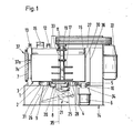
- FIG. 1 the vertical section through a pressure mixer according to the invention with the vertical axis of rotation of the mixing container 1 is shown.
- the pressure vessel 3 is mounted on a frame 14. Inside the pressure vessel 3, the mixing vessel 1 is rotatably mounted on a ball bearing 2.
- the emptying opening 20 of the mixing container 1 is closed by a closure lid 8, which is connected to the mixing container 1 in a tightly sealing manner by a stationary seal and is rotatably and pivotably mounted on the closure lid mechanism 21.
- the passage opening 18 of the pressure vessel bottom 31 enables the closure cover 8 to be inserted into the emptying opening 20 and the mixture to pass through when the cover 8 is open and after the mixing process has ended.
- the emptying and the passage openings 20 and 18 are formed by the outlet ring 25, on the outside of which the sliding seal 9 establishes the connection to the sealing edge 26 of the pressure vessel base 31.
- the ball bearing 2 is surrounded by a ring gear 4, in which a pinion 5 engages, which in turn is driven by the shaft 34 of the motor 6 provided with a sliding seal 10 and thus causes the mixing container 1 to rotate.
- the shaft 33 provided with the sliding seal 11 for the mixing tools 17 is driven via V-belts.
- the shaft is provided below the sliding seal 11 with a protective ring 19, which serves to protect the sliding seal 11 from whirled up mix.
- a seal 16 attached to the cover 27 of the pressure vessel 3 lies against the upper edge of the mixing vessel 1 and prevents mixed material from passing out of the mixing vessel ter 1 in the space surrounding the mixing vessel 1 of the pressure vessel 3.
- the pressure flange 13 is also arranged on the lid 27 of the pressure vessel 3, but is located outside of the circle described by the seal 16. In this way, gas introduced through the pressure flange 13 first flows into the space of the pressure container surrounding the mixing container and from there through the seal 16, which only seals tightly for mixed material, into the mixing container 1.
- openings 37 and 37a through which the interior of the mixing vessel 1 is made accessible, are provided at the same height by the covers 7 and 7a. This enables maintenance and repair work, for example on the mixing tools 17, or also the replacement of wear linings 23 with which the inside of the mixing container 1 can be lined.
- FIGS. 2 and 3 show details of the mounting of the mixing container 1 and the sealing of the mixing or pressure container 1 or 3 in the region of the bottom-side emptying or passage opening 20 or 18.
- FIG 23 shown. 2 shows in cross section the ball bearing 2 with the ring gear 4 surrounding the ball bearing 2.
- the discharge opening 20 and the passage opening 18 are enclosed by an outlet ring 25 which is fixed to the bottom of the mixing container 1 connected is.
- the sliding seal 9 which seals the interior of D ruckbenzol- ters 3 and the associated mixing container 1 against the surroundings, wherein the mixing vessel 1 to the outlet ring 25 relative to the pressure vessel 3 is rotatable with the sealing edge 26 along the sliding seal 9.
- the diameter of the outlet ring 25 and the sealing edge-26 is chosen so that the sliding seal 9 can be a seal in a commercially available shape and size.
- FIG. 3 shows another form of a mixing container wall 3, which in this case is designed as a hollow wall and through which a coolant or heating medium flows.
- supply lines 24 are inserted in a conventional manner in a pressure-tight manner through the bottom 31 of the pressure vessel 3 into the sealing edge 26 and open there in the interspaces of three annular sliding seals 9 arranged one above the other.
- the outlet ring 18 is provided over its entire circumference with bores which in turn are provided create the connection from these gaps to the interior of the mixing container wall 3l.
- a partition divides the interior of the mixing container wall 31 into two subspaces connected at the upper edge of the mixing container 1, one of which is connected to the inlet and the other to the outlet of the heating or coolant supply lines 24. In this way, an effective heat exchange is achieved on the entire mixing container wall 31.
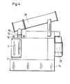
- Figures 4 and 5 show two embodiments of a pressure-resistant mixer according to the invention in side view.
- the axis of rotation of the mixing container 1 is vertical, in Figure 5 this axis is slightly inclined.
- the outline shows some of the components already mentioned in the description of FIG. 1, namely the machine frame 14, the drive motor 22, and the pressure vessel 3 with filler Opening 15, vacuum flange 12, pressure flange 13 and the side wall opening closed by the pressure plate 7.
- a condenser 29 is attached to the cover 27 of the pressure vessel 3 and is connected at its lower end to the vacuum flange 12.
- the gas drawn off by the vacuum flange 12 condenses in a heat exchanger of the condenser 29 and can then be fed back to the mixture in liquid form through the same opening.
- the vacuum flange 12 is shown larger than the fill opening 15 and the pressure flange 13.
- Figure 5 only the vacuum opening 12 is shown.
- the condensate flows back through the vacuum flange 12 into the interior of the mixing container 1, it can be dammed up in front of a collecting plate 39 in the lower region of the condenser 29 and, if necessary, can flow through the outlet 36 after opening the valve 32.
- This option will be chosen if, for example, solvents are removed from the mix and should not flow back into the mix.
- the solvent flowing off through the outlet 36 can then be collected outside the mixing container 1, preferably also outside the pressure container 3, and can be used again for the next batch, for example.
- the enlarged section in FIG. 5 indicates how, on the one hand, a gaseous substance is pumped into the condenser through an attachment pipe on the vacuum flange 12, while at the same time the cooled and again condensed gas flows back into the mixing container 1 as a liquid through the same opening.
- FIG. 6 shows a pressure-resistant mixer in which the mixing container 1 is driven by the drive motor 6 via a friction wheel 5a.
- the sliding seal 10 or the associated outer frame of the sliding seal 10 is pressure-tight with an elastic sleeve 10a connected to the opening in the bottom 31 of the pressure vessel 3.
- the shaft 34 of the drive motor 6 has enough play to adapt to the radial movements of the friction wheel 5a on the drive ring 4a with respect to the mixing container axis 35 without mechanically stressing the sliding seal 10, which could otherwise lead to leaks.
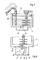
- FIG. 7 shows a pressure-resistant mixer in an embodiment in which there is no emptying opening 20 in the bottom 28 of the mixing container 1 but instead a suction tube 38 which is movable in the vertical direction and is attached to the cover 27, through which flowable mixture is sucked out of the mixing container 1 can.
- the suction pipe 38 is connected to a flange 42 of the cover 27 of the pressure vessel 3 via a seal (not visible here) and can be moved up and down in the vertical direction, so that the end of the suction pipe 38 is either above the material as required or immersed in it.
- the ability to pull the suction pipe 38 out of the mix can be advantageous in that the mix. during the mixing process can have a very viscous consistency or even partially have solids with a very rough structure A suction pipe 38 immersed in the material to be mixed would then be subjected to unnecessary mechanical loads and would also disrupt the circulation of the material to be mixed.
- such a suction pipe has the advantage that there is no need for an emptying opening 20 on the bottom 28 of the mixing container 1 and no through opening 18 for the mixing material on the bottom 31 of the pressure container 3.
- the relatively large sliding seal 9 can thus also be omitted, so that at most the sliding seal 10 for the shaft 34 of the drive motor 6 must be present in the bottom 31 of the pressure vessel 3, which in this embodiment is expediently firmly connected to the bottom of the mixing vessel bottom 28 in this embodiment.
- FIG. 8 shows a further embodiment of the pressure-resistant mixer, in which the still relatively large sliding seal 9 on the outlet ring 25 (see FIG. 2) can also be omitted.
- the closure cover 8 of the mixing container 1 in addition to the closure cover 8 of the mixing container 1, there is also a pressure closure cover 40 for the passage opening 18 of the pressure container 3.
- the closure cover 8 can be moved relative to it in the direction of the axis of symmetry of the concentric covers 8, 40 by a hydraulic or pneumatic drive on the closure cover mechanism 21 or on the pressure closure cover 40. In the open state, the two covers 8, 40 essentially rest on one another. After closing the pressure closure lid 40 with the aid of the closure lid mechanism 21, the closure lid 8 is then pressed into the emptying opening 20 of the mixing container 1 with the aid of the additional drive 41.
- the cover 8 is rotatably mounted on the additional drive. However, the pressure-tight sealing of the emptying or passage opening 20 or 18 takes place by means of a stationary seal on the edge of the pressure closure cover 40. The use of the relatively large sliding seal 9 can also be avoided in the case of non-flowable mixed materials. If the drive motors 6 and 22 for the mixing container 1 and the mixing tools 17 are also arranged in the pressure vessel 3, such a pressure-resistant mixer can be operated completely without sliding seals and thus meet particularly high sealing requirements.
Landscapes
- Chemical & Material Sciences (AREA)
- Chemical Kinetics & Catalysis (AREA)
- Mixers Of The Rotary Stirring Type (AREA)
- Processing And Handling Of Plastics And Other Materials For Molding In General (AREA)
- Preparation Of Clay, And Manufacture Of Mixtures Containing Clay Or Cement (AREA)
- Pressure Vessels And Lids Thereof (AREA)
- Mixers With Rotating Receptacles And Mixers With Vibration Mechanisms (AREA)
- Accessories For Mixers (AREA)
- Processing Of Solid Wastes (AREA)
Abstract
Description
- Die Erfindung betrifft einen druckfesten Mischer mit einer Einfüllöffnung, einem sich drehenden, eine Entleerungseinrichtung aufweisenden Mischbehälter, mit exzentrisch zur Mischbehälterachse angeordneten Mischwerkzeugen im Inneren des Mischbehälters und mit Antriebsmotoren und Abtriebsmitteln zum Antrieb der Mischwerkzeuge und/oder des Mischbehälters.
- Für eine Vielzahl von Aufgaben im Bereich der Verfahrenstechnik ist die Aufbereitung von Materialien unter Druck oder Vakuum notwendig oder vorteilhaft. Absaugen von Lösungsmitteln, blasenfreies Aufbereiten von Lacken, Mischen und Kneten explosiver Massen unter Schutzgas sind Beispiele für solche Aufgaben.
- Nach dem Stand der Technik werden für solche Mischaufgaben (unter diesem Begriff sind auch Kneten, Agglomerieren, Reiben, Rühren, Plastifizieren usw. zu verstehen) vorwiegend Maschinen mit stationären Mischgutbehältern eingesetzt.
- Es handelt sich hierbei vorwiegend um zylindrische Mischgutbehälter in stehender oder liegender Anordnung mit zentrischen oder planetenartig umlaufenden Mischwerkzeugwellen.
- Nachteilig ist bei diesen Maschinen, daß die Dichtungen ) zwischen dem Druckbehälter, der gleichzeitig den Mischbehälter bildet, und den hineinragenden Mischwerkzeugwellen im mischgutbeaufschlagten Bereich liegen. Diese Dichtungen sind damit einem starken Verschleiß, Verschmutzung, und auch chemischen Angriffen ausgesetzt. Dies führt häufig zu aufwendigen Wartungsarbeiten im Bereich der Dichtungen mit entsprechend langen Stillstandszeiten der Maschine.
- Weiterhin sind auch unter Druck oder Vakuum arbeitende Mischer bekannt, deren Behälter um eine horizontale oder geneigte Achse rotieren. Diese Maschinen haben in der Regel keine Mischwerkzeuge, sondern arbeiten nach dem Prinzip des freien Falles. Die Aufbereitung von schwerfließenden und klebrigen Mischgütern ist in solchen Maschinen nicht möglich, da der Einbau von Abstreifern zur Reinigung der Behälterwände nicht möglich ist. Ein weiterer Nachteil dieser Maschinen besteht darin, daß sie zum Beschicken und Entleeren jeweils angehalten werden müssen, wobei die Be-schickungs- und die Entleeröffnung jeweils an die entsprechenden Anschlußgeräte angeflanscht werden müssen. Außerdem können an derartigen Mischern Anschlußleitungen zur Aufrechterhaltung eines Unter- bzw. Überdruckes nur konzentrisch an der Antriebswelle angebracht werden, wodurch wiederum mischgutbeaufschlagte Gleitdichtungen erforderlich sind.
- Allen bisherigen Mischerkonstruktionen für Druck- oder Vakuumbetrieb haftet der Nachteil an, daß das Anbringen von Verschlei-ß- bzw. Schutzbelägen im Inneren -des Mischbehälters durch Schrauben nur schwer möglich ist. Das druckfeste Abdichten einer Vielzahl von durchgehenden Schraubenlöchern ist äußerst aufwendig und nicht betriebssicher. Das Anbringen von Gewindesacklöchern ist ebenfalls aufwendig, zudem sind derartige Gewindesacklöcher sehr schmutzempfindlich.
- Bei der Befestigung von Verschleißbelägen mittels Schwei-Ben wird dagegen das Austauschen der Beläge sehr erschwert.
- Aus der DE-PS 24 28 414 ist ein Kneter bekannt, bei dem ein Mischgutbehälter dreiseitig durch einen Druckbehälter umgeben ist. Die beiden Stirnseiten und die Oberseite sind i jedoch gleichzeitig Mischbehälter- und Druckbehälterwandungen.
- Die oben genannten Probleme mit der Befestigung der Verschleißbeläge treten bei dieser Maschine an den Stirnseiten ebenfalls auf.
- Außerdem ist bei dieser Maschine die Zugänglichkeit zum Mischbehälter durch den Druckbehälter besonders im unteren Bereich, der ja gerade am stärksten dem Verschleiß ausgesetzt ist, sehr schlecht.
- Durch den stillstehenden, asymmetrischen Behälter kann dieser nicht allseitig durch Mischwerkzeuge oder Abstreifer bestrichen werden, so daß die Mischung klebriger Produkte problematisch ist.
- Darüberhinaus liegen die druckbeaufschlagten Dichtungen der Werkzeuglagerungen sämtlich im Mischgutbereich.
- Schließlich ist der Mischgutaustrag über eine Förderschnekke für schwer fließende oder grobkörnige Mischgüter ungeeignet.
- Eine Reihe von Mischaufgaben ist besonders gut mit sogenannten Intensivmischern zu lösen, die einen um eine vertikale oder leicht geneigte Achse rotierenden Mischteller (Mischbehälter) mit darin exzentrisch angeordneten Mischwerk-5 zeugen aufweisen. Solche Maschinen haben sich insbesondere bei der Mischung schwer fließender, pastöser und plastischer Massen bewährt. Es war bisher nicht möglich, dieses besonders wirkungsvolle Mischsystem für Druck- oder Vakuumbetrieb auszulegen, da die hierbei erforderlichen Gleitdichtungen extrem groß und darüberhinaus auch schädlichen Mischguteinflüssen ausgesetzt gewesen-wären.
- Die zu lösende technische Aufgabe besteht nun darin, einen druckfesten Mischer herzustellen, der einerseits keine mischgutbeaufschlagten Gleitdichtungen aufweist und der andererseits auch ohne die Verwendung extrem großer Gleitdichtungen nach dem Prinzip der Intensivmischer arbeiten kann.
- Diese Aufgabe wird dadurch gelöst, daß um den Mischbehälter herum ein Druckbehälter angeordnet ist.
- Diese Trennung von Druckbehälter und Mischbehälter erlaubt das Anbringen von Gleitdichtungen in Bereichen, die nicht mit dem Mischgut in Berührung kommen. Weiterhin ist es möglich, einen Intensivmischer im Inneren eines Druckbehälters anzuordnen, wobei die zu verwendenden Gleitdichtungen in ihrer Größe nicht durch die exzentrische Anordnung der Mischwerkzeuge festgelegt werden, sondern lediglich durch den Durchmesser der Antriebswelle für Mischwerkzeuge und Mischbehälter und durch den Durchmesser einer Entleeröffnung bestimmt sind.
- Vorteilhaft im Sinne einer einfachen und preiswerten Herstellungsweise ist es dabei, wenn erfindungsgemäß der Druckbehälter im wesentlichen ein zylindrischer Behälter mit Boden, Deckel und Wand und der Mischbehälter im wesentlichen ein zylindrischer Behälter mit Boden, Wand und ohne Deckel ist. Zylindrische Behälter lassen sich im allgemeinen recht leicht herstellen und sind zum anderen aufgrund ihrer geometrischen Form vor allem als Druckbehälter gut geeignet.
- Ebenso ist es zweckmäßig, wenn der Mischbehälter im Inneren des Druckbehälters drehbar gelagert ist. Auf diese Weise kann das Prinzip der Intensivmischer angewendet werden.
- Gemäß der Erfindung ist es von Vorteil, wenn der Antriebsmotor des Mischbehälters außerhalb des Druckbehälters angeordnet und als Abtriebsmittel eine durch den Boden des Druckbehälters geführte, mit einer Gleitdichtung versehene Welle vorgesehen ist, an deren Ende im Inneren des Druckbehälters ein Ritzel angebracht ist, das mit einem Zahnrad am Boden des Mischbehälters kämmt.
- Auf diese Weise ist der Motor leicht zugänglich und einfach zu kühlen, und die erforderliche Gleitdichtung der Antriebswelle liegt außerhalb des Mischbehälters und ist somit nicht den Einflüssen des Mischgutes ausgesetzt.
- Eine weitere, vorteilhafte Ausführungsform eines Mischers gemäß der Erfindung ist dadurch gekennzeichnet, daß der Antriebsmotor des Mischbehälters außerhalb des Druckbehälters angeordnet und daß als Abtriebsmittel eine durch eine elastische Manschette am Boden des Druckbehälters geführte, mit einer Gleitdichtung versehene Welle vorgesehen ist, an deren Ende im Inneren des Druckbehälters ein Reibrad angebracht ist, das an einem Antriebsring des Mischbehälters anliegt.
- Der Antrieb von Mischbehältern mittels Reibrad hat sich als besonders wartungs- und geräuscharm bewährt. Durch die Flexibilität des Reibrades wird jedoch auch die elastische Lagerung des Antriebsmotors und der Antriebswelle erforderlich. Zum Ausgleich der bezüglich der Mischbehälterachse radialen Bewegung der Motorwelle kann die Gleitdichtung der Welle bzw. ihrer Einfassung über eine Manschette, die z.B. aus einer Gummiplatte bestehen kann, mit dem Gehäuse des Druckbehälters verbunden werden. Eine derartige Manschette hat vorteilhafterweise gleichzeitig eine schall-und vibrationsdämpfende Wirkung.
- Ebenfalls vorteilhaft bei einem Mischer gemäß der Erfindung ist es, wenn der Antriebsmotor für die Mischwerkzeuge außerhalb des Druckbehälters an dessen Deckel oder Seitenwand oder am Maschinenrahmen angebracht und über eine durch den Deckel des Druckbehälters geführte und mit einer Gleitdichtung versehene Welle mit den Mischwerkzeugen im Inneren des Mischbehälters verbunden ist.
- Auch in diesem Fall ist der Motor leicht zugänglich, und die Gleitdichtung für die Welle der Mischwerkzeuge kommt im allgemeinen, da sie am Deckel des Druckbehälters angeordnet ist, ebenfalls nicht mit dem Mischgut in Berührung. Im Fall von stark aufwirbelndem Mischgut kann die Welle vorteilhafterweise zusätzlich mit einem Schutzring unterhalb der Gleitdichtung versehen werden.
- Die Erfindung sieht vorteilhafterweise weiterhin vor, daß sich am Boden des Druckbehälters konzentrisch zur Achse des Mischbehälters und einer Entleeröffnung am Boden des Mischbehälters eine Durchtrittsöffnung befindet, die durch einen am Rand der Entleeröffnung angebrachten Auslaufring gebildet wird, der an seiner Außenseite über eine Gleitdichtung mit einem konzentrisch zur Durchtrittsöffnung verlaufenden Dichtungsrand am Boden des Druckbehälters verbunden ist.
- Da der Mischbehälter im Inneren des Druckbehälters angeordnet ist und da sich bei dieser Ausführungsform in der Bodenmitte des Mischbehälters eine Entleeröffnung mit einem Verschlußdeckel befindet, ist zweckmäßigerweise konzentrisch zu dieser Entleeröffnung im darunter befindlichen Boden des Druckbehälters eine Durchtrittsöffnung vorgesehen. Diese Durchtrittsöffnung dient zum einen dem Durchtritt des VerschluBdeckels der Entleeröffnung und zum anderen auch dem Durchtritt des aus der Entleeröffnung herausfließenden bzw. herausfallenden Mischgutes. Durchtritts-und Entleeröffnung sind durch einen Auslaufring miteinander verbunden, dessen oberer Rand zweckmäßigerweise dichtschließend und fest mit dem Rand der Entleeröffnung ver- Junden ist und dessen unterer Rand über eine außen an ihm anliegende Gleitdichtung mit dem Dichtungsrand der Durchtrittsöffnung des Druckbehälters verbunden ist. Die Durchtrittsöffnung wird somit durch den unteren Innenbereich des Auslaufringes gebildet.
- Diese Anordnung der Öffnung hat den Vorteil, daß die Gleitdichtung zwischen Auslaufring und Dichtungsrand einen minimalen Durchmesser haben kann, wodurch der Anwender gegebenenfalls auf relativ preiswerte Dichtungen mit Standardmaßen zurückgreifen kann, die im einschlägigen Fachhandel erhältlich sind. Die Anordnung der Gleitdichtung hat wiederum den Vorteil, daß letztere nicht mit dem Mischgut in Berührung kommt.
- Ein weiterer Vorteil liegt dabei auch darin, daß der Verschlußdeckel für die Entleeröffnung auf der Verschlußdekkelmechanik drehbar gelagert ist und im geschlossenen Zustand über eine stationäre Dichtung fest mit dem sich drehenden Mischbehälter verbunden ist. Stationäre Dichtungen sind aus wesentlich unempfindlicheren und robusteren Materialien herstellbar als Gleitdichtungen und können darüberhinaus auch fest an die Dichtflächen angepreßt werden, so daß ihre Beaufschlagung mit Mischgut ohne weiteres in Kauf genommen werden kann, da ohne Relativbewegung zwischen Verschlußdeckel und Öffnungsrand kein Verschleiß an der Dichtung auftritt.
- Bei einer Ausführungsform des druckfesten Mischers für gut fließende Mischgüter ist es vorteilhaft, wenn durch den Deckel des Druckbehälters ein im wesentlichen senkrecht zur Deckelebene bewegbares und an seiner Außenseite gegen den Deckel abgedichtetes Saugrohr zur Entnahme von saugfähigem Mischgut angeordnet ist.
- Auf diese Weise kann die Entleeröffnung im Mischbehälterboden durch das Saugrohr ersetzt werden. Das Mischgut kann dann am Ende der Mischzeit durch eine Pumpe aus dem Mischer gesaugt werden. Der VerschluBdeckel und die dafür erforderlichen Antriebsteile werden bei dieser Lösung eingespart, und der Durchmesser der benötigten Gleitdichtungen wird auf den Durchmesser einer Antriebs- oder Lagerwelle für den Mischbehälter beschränkt, die in diesem Fall zweckmäßigerweise auch zentral angeordnet ist. Vorzugsweise ist das Saugrohr heb- und senkbar angeordnet, so daß während des Mischvorganges, bei dem das Mischgut unter Umständen sehr zähflüssig sein kann, keine Störung der Mischgutzirkulation auftritt.
- Die um das Saugrohr anliegende Dichtung kann z.B. eine Quetschverschraubung sein, die zum einen das Heben und Senken des Saugrohres ermöglicht und gleichzeitig als Feststelleinrichtung dient, mit Hilfe derer die jeweils gewünschte Höhe der Saugrohröffnung eingestellt wird. Der Fachmann kann hier die für den jeweiligen Zweck am besten geeignete Dichtung und/oder Feststelleinrichtung wählen.
- Im kontinuierlichen Betrieb kann die Unterkante des Saugrohres so eingestellt werden, --daß -der Abstand vom Mischbehälterboden der gewünschten Mischgutschichthöhe entspricht. Bei kontinuierlichem Betrieb entspricht dann der jeweilige Füllgrad auch gerade der durchschnittlichen Verweilzeit des Mischgutes.
- Sofern im Inneren des Druckbehälters Unterdruck herrscht, muß der Druck im Saugrohr selbstverständlich noch unter dem Restdruck des Druckbehälters liegen, damit eine Entnahme überhaupt möglich ist. Gegebenenfalls kann der Druckbehälter während der Entnahme von Mischgut durch das Saugrohr auch kurzzeitig mit geringem Druck beaufschlagt werden, um so die Entnahme des Mischgutes zu beschleunigen.
- ) Nach der Erfindung ist am Deckel des Druckbehälters über der Wand des Mischbehälters und/oder am oberen Rand desselben eine gegen Mischgut dichte Gleitdichtung angebracht. Eine derartige Dichtung hat den Vorteil, daß durch die
- Mischwerkzeuge aufgewirbeltes'Mischgut (Staub, Sand, etc.) nicht in den Bereich des Druckbehälters außerhalb des Mischbehälters gelangt, wo sich die empfindlicheren druckfesten Gleitdichtungen befinden.
- Weiterhin sind am Deckel eines Druckbehälters gemäß der Erfindung über dem Mischbehälter zusätzlich zur Einfüllöffnung noch ein Vakuumflansch zum Anbringen einer Absaug- bzw. Vakuumpumpleitung und an der Zylinderwand oder am Deckel des Druckbehälters außerhalb der eben erwähnten Mischgutdichtung ein Druckflansch zum Anschluß einer Druckleitung angebracht. Derartig angebrachte Vakuum- und Druckflansche sind zum einen unabhängig von Einfüllvorgängen und zum anderen strömt auf diese Weise zugeführtes oder abgesaugtes Gas immer vom äußeren Bereich des Druckbehälters in den Mischbehälter hinein, so daß auf diese Weise ebenfalls vermieden wird, daß aufgewirbeltes Mischgut in den Außenbereich des Mischbehälters gelangt.
- ) Ein weiteres Merkmal der Erfindung liegt darin, daß in der Wand des Druckbehälters durch Druckplatten verschließbare Öffnungen mit druckfesten Dichtungen und in der Wand des Mischbehälters auf gleicher Höhe durch Platten verschließbare Öffnungen mit gegen Mischgut dichten Dichtungen angebracht sind. Diese Öffnungen ermöglichen es, von außen an funktionswesentliche Teile des Mischers, wie z.B. die Mischwerkzeuge, zu gelangen oder beispielsweise den Mischbehälter von innen mit Verschleißbelägen auszukleiden. Dabei ist es weiterhin zweckmäßig und vorteilhaft, wenn die Schleißbeläge durch einfache Durchgangsbohrungen in der Wand und/oder im Boden des Mischbehälters befestigt sind, die einen einfachen und schnellen Austausch erlauben.
- Für bestimmte Anwendungen ist es zweckmäßig, wenn bei einem Mischer nach der Erfindung am Deckel des Druckbehälters ein Kondensator zum Kondensieren von aus dem Mischgut abgepumpten Gasen angeordnet ist. Dabei kann es von Vorteil sein, wenn der Kondensator für den Rückfluß des Kondensats an seiner tiefsten Stelle mit dem Vakuumflansch oder einer anderen Öffnung des Deckels des Druckbehälters über dem Mischbehälter verbunden ist. So gibt es z.B. Mischvorgänge, bei denen aufgrund des Mischvorgangs physikalische oder chemische Reaktionen Wärmeenergie erzeugen und das Mischgut u.U. in unerwünschter Weise aufheizen. Eine derartige Erwärmung kann vermieden werden, indem z.B. ein teilweise gasförmiger Bestandteil des Mischgutes abgepumpt wird, wobei die durch das Abpumpen erzwungene weitere Verdampfung dieses Bestandteiles dem Mischgut die dafür erforderliche Verdampfungswärme entzieht. Da sich jedoch im allgemeinen die Zusammensetzung des Mischgutes nicht ändern soll, ist es vorteilhaft, wenn das abgepumpte Gas in einem Kondensator (Wärmetauscher) kondensiert und anschließend in flüssiger Form wieder dem Mischgut zugeführt wird.
- In einer weiteren Ausführungsform eines druckfesten Mischers gemäß der Erfindung ist ebenfalls am Deckel des Druckbehälters ein Kondensator angeordnet, der an seiner >tiefsten Stelle mit einem Ablauf, welcher außerhalb des Mischbehälters mündet, verbunden ist.
- Dies wäre z.B. dann zweckmäßig, wenn durch das Abpumpen ein Lösungsmitte] aus dem Mischgut entfernt werden soll. Vorteilhafterweise ist dabei der Ablauf so angebracht, daß er nicht nur außerhalb des Mischbehälters sondern auch außerhalb des Druckbehälters mündet. Am Ablauf können die Lösungsmittel zurückgewonnen und in der nächsten Charge wieder verwendet werden.
- Oberhalb des Mischgutes oder direkt in Kontakt mit diesem können am Deckel des Druckbehälters Druck- und/oder Temperaturmeßgeräte angeordnet sein, die mit einer Steuereinrichtung zum Einstellen eines bestimmten Druckes bzw. einer bestimmten Pumpleistung gekoppelt sind. Da Druck und Temperatur für gasförmige Systeme voneinander abhängig Variable sind, kann so in vorteilhafter Weise durch eine entsprechende Einstellung des Druckes eine Temperaturregelung vorgenommen werden.
- Eine andere Möglichkeit zur Temperaturregelung des Mischgutes kann durch eine weitere Ausführungsform eines Druckmischers erfolgen, bei der Wand und Boden des Mischbehälters für den Durchfluß eines Kühl- und/oder Heizmittels hohl sind.
- Erfindungsgemäß sind bei einem derartigen druckfesten Mischer am Boden des Druckbehälters neben der Durchtrittsöffnung Zuleitungen angeordnet, die durch den Dichtungsrand hindurchgeführt sind und in den Zwischenräumen von drei zwischen dem Dichtungsrand und dem Auslaufring in Abständen übereinanderliegenden Gleitdichtungen münden. Die für den Druckbetrieb erforderliche Dichtung um die Durchtrittsöffnung ist dabei also so ausgeführt, daß zwischen mehreren einzelnen Dichtringen mindestens zwei Kammern entstehen, die für die Zufuhr und/oder Abfuhr von Kühl- und/ oder Heizmedien durch entsprechende Zuleitungen geeignet sind. Das Innere der Wand und des Bodens des Mischbehälters sind dabei über auf dem ganzen Rand des Auslaufringes angebrachte Bohrungen mit denselben Zwischenräumen der Gleitdichtungen verbunden, in denen die Zuleitungen münden. Zweckmäßigerweise ist das Innere des Bodens und der Wand des Mischbehälters noch durch eine weitere Trennwand in zwei Bereiche aufgeteilt, von denen einer mit dem Zulauf und der andere mit dem Ablauf der Heiz- oder Kühlflüssigkeit verbunden ist und die am oberen Rand der Mischbehälterwand miteinander verbunden sind. Auf diese Weise muß das zufließende Heiz- oder Kühlmittel an der gesamten Boden- und Wandfläche des Mischbehälters entlangfließen, bevor es in den Abfluß gelangt, so daß eine sehr effektive Heizung oder Kühlung erreicht wird. Eine derartige Heiz- bzw. Kühlmöglichkeit des Mischbehälters ist vor allem dann vorteilhaft, wenn das Mischgut kaum gasförmige Bestandteile enthält und eine Temperaturregulierung durch Einstellen des Gasdruckes nicht möglich ist.
- Im Hinblick auf die vielseitige Verwendbarkeit des Mischers wählt man gemäß der Erfindung mit Vorteil derartige druckfeste Dichtungen aus, die sowohl gegen Überdruck als auch gegen Unterdruck dicht sind.
- In einer weiteren besonderen Ausführungsform des druckfesten Mischers, bei der besonders hohe Anforderungen an die Dichtheit des Systems gestellt werden, ist zusätzlich zu dem Verschlußdeckel für den Mischbehälter ein weiterer 3 Druckverschlußdeckel für den Druckbehälter vorhanden. Beide Deckel können auf demselben Schwenkarm befestigt sein. Während der Druckverschlußdeckel bereits durch die Schwenkbewegung der Verschlußdeckelmechanik in seine geschlossene Endlage gebracht wird, erfolgt das Schließen und das ) Anpressen des Verschlußdeckels für den Mischbehälter durch einen am Schwenkarm bzw. am Druckverschlußdeckel angebrachten Zusatzantrieb, z.B. Feder, Hydraulik- oder Pneumatikzylinder, Elektromotor etc. Dabei ist der Verschlußdeckel für den Mischbehälter auf dem Zusatzantrieb drehbar gela-5 gert.
- Auf diese Weise kann man im Bereich des Auslaufringes ausschließlich mit stationären Dichtungen arbeiten und auf die bei sehr hohen Dichtigkeitsanforderungen problematische Gleitdichtungen verzichten.
- Darüberhinaus kann diese Ausführungsform dahingehend erweitert werden, daß auch die Antriebsmotoren für den Mischbehälter und die Mischwerkzeuge im Inneren des Druckbehälters angeordnet sind, so daß auch die relativ kleinen Gleitdichtungen der Antriebswellen für den Mischbehälter und die Mischwerkzeuge entfallen können. Bei einer derartigen Ausführungsform des druckfesten. Mischers können daher ausschließlich stationäre Dichtungen verwendet werden. Dies kann dann vorteilhaft oder sogar notwendig sein, wenn besonders große Differenzen gegenüber dem Atmosphärendruck vorliegen oder wenn im Inneren des Druckbehälters mit giftigen Gasen gearbeitet wird. Die druckdichte Zuführung von elektrischen Anschlüssen und Kühlmitteln für die Antriebsmotoren kann dabei auf konventionelle und bekannte Weise erfolgen.
- Weitere Vorteile, Merkmale und Anwendungsmöglichkeiten der vorliegenden Erfindung ergeben sich aus der folgenden Beschreibung konkreter Ausführungsformen und der dazugehörigen Zeichnungen. Es zeigen:
- Figur 1 einen Schnitt entlang einer vertikalen Ebene durch einen Druckmischer gemäß der Erfindung,
- Figur 2 ein Schnittbild von einem Teil des Mischbehälterbodens mit Auslaufring und Druckbehälterboden,
- Figur 3 den Schnitt durch einen Mischbehälter mit hohler Wand und die zugehörigen Dichtungen und Zuleitungen,
- Figur 4 die Seitenansicht eines Druckmischers mit Kondensator und mit vertikaler Drehachse des Mischbehälters,
- Figur 5 einen Mischbehälter mit Kondensator und geneigter ) Achse des Mischbehälters,
- Figur 6 ein Schnittbild eines druckfesten Mischers mit Reibradantrieb für den Mischbehälter,
- Figur 7 ein Schnittbild durch einen druckfesten Mischer mit einem Saugrohr als Entleereinrichtung und
- Figur 8 ein Schnittbild eines druckfesten Mischers mit Verschlußdeckel und zusätzlichem Druckverschlußdeckel.
- In Figur 1 ist der vertikale Schnitt durch einen Druckmischer gemäß der Erfindung mit vertikaler Drehachse des Mischbehälters 1 dargestellt. Auf einem Rahmen 14 ist der Druckbehälter 3 montiert. Im Inneren des Druckbehälters 3 ist der Mischbehälter 1 auf einem Kugellager 2 drehbar gelagert. Die Entleeröffnung 20 des Mischbehälters 1 ist durch einen VerschluBdeckel 8, der über eine stationäre Dichtung dicht schließend mit dem Mischbehälter 1 verbunden und auf der Verschlußdeckelmechanik 21 drehbar und schwenkbar gelagert ist, verschlossen.
- Die Durchtrittsöffnung 18 des Druckbehälterbodens 31 ermöglicht zum einen den Einsatz des Verschlußdeckels 8 in die Entleeröffnung 20 und zum anderen den Durchtritt des Mischgutes bei geöffnetem Deckel 8 und nach beendigtem Mischvorgang. Die Entleer- und die Durchtrittsöffnung 20 und 18 werden gebildet vom Auslaufring 25, an dessen Außenseite die Gleitdichtung 9 die Verbindung zum Dichtungsrand 26 des Druckbehälterbodens 31 herstellt. Das Kugellager 2 ist umgeben von einem Zahnkranz 4, in den ein Ritzel 5 eingreift, das seinerseits über die mit einer Gleitdichtung 10 versehene Welle 34 des Motors 6 angetrieben wird und so die Drehung des Mischbehälters 1 bewirkt. Mit Hilfe des Antriebsmotors 22, der am Maschinenrahmen 14 befestigt ist, wird über Keilriemen die mit der Gleitdichtung 11 versehene Welle 33 für die Mischwerkzeuge 17 angetrieben. Die Welle ist unterhalb der Gleitdichtung 11 mit einem Schutzring 19 versehen, der zum Schutz der Gleitdichtung 11 vor aufgewirbeltem Mischgut dient.
- Eine am Deckel 27 des Druckbehälters 3 angebrachte Dichtung 16 liegt am oberen Rand des Mischbehälters 1 an und verhindert den Durchtritt von Mischgut aus dem Mischbehälter 1 in den den Mischbehälter 1 umgebenden Raum des Druckbehälters 3. Über dem Mischbehälter 1 befinden sich am Deckel 27 des Druckbehälters 3 die Einfüllöffnung 15 und der Absaugflansch 12. Der Druckflansch 13 ist ebenfalls am Deckel 27 des Druckbehälters 3 angeordnet, befindet sich jedoch außerhalb des von der Dichtung 16 beschriebenen Kreises. Auf diese Weise strömt durch den Druckflansch 13 eingeleitetes Gas zunächst in den den Mischbehälter umgebenden Raum des Druckbehälters und von dort durch die lediglich für Mischgut dichtschließende Dichtung 16 in den Mischbehälter 1 ein. Wird andererseits am .Absaugflansch 12 dem Mischbehälter 1 Gas entzogen, so strömt das außerhalb des Mischbehälters 1 im Druckbehälter 3 befindliche Gas ebenfalls von außen durch die Dichtung 16 nach. Auf diese Weise wird verhindert, daß ein Gasstrom aus dem Mischbehälter 1 durch die Dichtung 16 in den umgebenden Raum des Druckbehälters 3 fließt, wobei unter Umständen Mischgut in diesen Bereich gelangen könnte.
- An der Seitenwand 36 des Druckbehälters 3 und des Mischbehälters 1 sind auf gleicher Höhe durch die Deckel 7 bzw. 7a verschlossene Öffnungen 37 bzw. 37a angebracht, durch die das Innere des Mischbehälters 1 zugänglich gemacht wird. Dies ermöglicht Wartungs- und Reparaturarbeiten beispielsweise an den Mischwerkzeugen 17 oder auch den Austausch von Verschleißbelägen 23, mit denen die Innenseite des Mischbehälters 1 ausgekleidet sein kann.
- Die Figuren 2 und 3 zeigen Details der Lagerung des Mischbehälters 1 und der Abdichtung des Misch- bzw. Druckbehälters 1 bzw. 3 im Bereich der bodenseitigen Entleer- bzw. Durchtrittsöffnung 20 bzw. 18. Außerdem ist in Figur 2 durch mehrere horizontale Linien ein Verschleißbelag 23 dargestellt. Man erkennt in Figur 2 im Querschnitt das Kugellager 2 mit dem das Kugellager 2 umgebenden Zahnkranz 4. Am Boden des Mischbehälters 1 werden die Entleeröffnung 20 und die Durchtrittsöffnung 18 von einem Auslaufring 25 umschlossen, der fest mit dem Boden des Mischbehälters 1 verbunden ist. Zwischen der Außenseite des Auslaufringes 25 und dem Dichtungsrand 28 des Druckbehälters 3 befindet sich die Gleitdichtung 9, die das Innere des Druckbehäl- ters 3 und des damit verbundenen Mischbehälters 1 gegen die Umgebung abdichtet, wobei der Mischbehälter 1 mit dem Auslaufring 25 gegenüber dem Druckbehälter 3 mit dem Dichtungsrand 26 entlang der Gleitdichtung 9 drehbar ist. Der Durchmesser des Auslaufringes 25 und des Dichtungsrandes-26 ist dabei so gewählt, daß die Gleitdichtung 9 eine Dichtung in handelsüblicher Form und Größe sein kann.
- Die Figur 3 zeigt zusätzlich zu dem in Figur 2 dargestellten Ausschnitt eine andere Form einer Mischbehälterwand3 , die in diesem Fall als Hohlwand ausgebildet ist und von einem Kühl- oder Heizmittel durchflossen wird. Zu diesem Zweck sind Zuleitungen 24 auf konventionelle Weise druckdicht durch den Boden 31 des Druckbehälters 3 in den Dichtungsrand 26 eingelassen und münden dort in den Zwischenräumen dreier übereinander angeordneter, ringförmiger Gleitdichtungen 9. Der Auslaufring 18 ist auf seinem ganzen Umfang mit Bohrungen versehen, die ihrerseits die Verbindung von diesen Zwischenräumen zum Inneren der Mischbehälterwand 3lherstellen. Eine Trennwand teilt das Innere der Mischbehälterwand 31 in zwei am oberen Rand des Mischbehälters 1 verbundene Teilräume, von denen einer mit dem Zulauf und der andere mit dem Ablauf der Heiz- bzw. Kühlmittelzuleitungen 24 verbunden ist. Auf diese Weise erreicht man einen effektiven Wärmeaustausch auf der gesamten Mischbehälterwand 31.
- Die Figuren 4 und 5 zeigen zwei Ausführungsformen eines druckfesten Mischers gemäß der Erfindung in der Seitenansicht Bei dem in Fig. 4 dargestellten druckfesten Mischer steht die Drehachse des Mischbehälters 1 vertikal, in Figur 5 ist diese Achse etwas geneigt. In beiden Figuren erkennt man im Umriß einige der bereits bei der Beschreibung der Figur 1 erwähnten Komponenten, nämlich den Maschinenrahmen 14, den Antriebsmotor 22, und den Druckbehälter 3 mit Einfüllöffnung 15, Vakuumflansch 12, Druckflansch 13 und der durch die Druckplatte 7 verschlossenen seitlichen Wandöffnung. Zusätzlich ist auf dem Deckel 27 des Druckbehälters 3 noch ein Kondensator 29 angebracht, der an seinem unteren Ende mit dem Vakuumflansch 12 verbunden ist. Das durch den Vakuumflansch 12 abgesaugte Gas kondensiert in einem Wärmetauscher des Kondensators 29 und kann anschließend durch dieselbe Öffnung in flüssiger Form wieder dem Mischgut zugeführt werden. In Figur 4 ist der Vakuumflansch 12 größer dargestellt als die Einfüllöffnung 15 und der Druckflansch 13. In Figur 5 ist ausschließlich die Vakuumöffnung 12 dargestellt.
- Bevor das Kondensat durch den Vakuumflansch 12 in das Innere des Mischbehälters 1 zurückfließt, kann es im unteren Bereich des Kondensators 29 vor einem Auffangblech 39 aufgestaut werden und bei Bedarf nach dem Öffnen des Ventils 32 durch den Ablauf 36 abfließen. Diese Möglichkeit wird man dann wählen, wenn beispielsweise aus dem Mischgut Lösungsmittel entfernt werden und nicht wieder in das Mischgut zurückfließen sollen. Das durch den Ablauf 36 abfließende Lösungsmittel kann dann außerhalb des Mischbehälters 1, vorzugsweise auch außerhalb des Druckbehälters 3, aufgefangen und beispielsweise für die nächste Charge wieder verwendet werden.
- Der vergrößerte Ausschnitt in Figur 5 deutet an, wie einerseits eine gasförmige Substanz durch ein Ansatzrohr auf dem Vakuumflansch 12 in den Kondensator hineingepumpt wird, während gleichzeitig durch dieselbe Öffnung das abgekühlte und wieder kondensierte Gas als Flüssigkeit in den Mischbehälter 1 zurückfließt.
- Die Figur 6 stellt einen druckfesten Mischer dar, bei dem der Mischbehälter 1 über ein Reibrad 5a vom Antriebsmotor 6 angetrieben wird. Die Gleitdichtung 10 bzw. die zugehörige äußere Fassung der Gleitdichtung 10 ist über eine elastische Manschette 10a druckdicht mit einer entsprechenden Öffnung im Boden 31 des Druckbehälters 3 verbunden. Auf diese Weise hat die Welle 34 des Antriebsmotors 6 genügend Spiel, um sich den bezüglich der Mischbehälterachse 35 radialen Bewegungen des Reibrades 5a auf dem Antriebsring 4a anzupassen, ohne dabei die Gleitdichtung 10 mechanisch zu belasten, was ansonsten zu Undichtigkeiten führen könnte.
- Figur 7 zeigt einen druckfesten Mischer in einer Ausführungsform, bei der sich im Boden 28 des Mischbehälters 1 keine Entleeröffnung 20 befindet sondern bei der stättdessen am Deckel 27 ein in vertikaler Richtung bewegbares Saugrohr 38 angebracht ist, durch das fließfähiges Mischgut aus dem Mischbehälter 1 abgesaugt werden kann. Das Saugrohr 38 ist dabei über eine hier nicht sichtbare Dichtung mit einem Flansch 42 des Deckels 27 des Druckbehälters 3 verbunden und kann in vertikaler Richtung auf und ab bewegt werden, so daß das Ende des Saugrohres 38 sich je-nach Bedarf entweder oberhalb des Mischgutes befindet oder in dieses eintaucht. Die Möglichkeit, das Saugrohr 38 aus dem Mischgut herauszuziehen, kann insofern von Vorteil sein, als das Mischgut . während des Mischvorganges u.U. eine sehr zähe Konsistenz haben kann oder auch teilweise Feststoffe von sehr grober Struktur aufweist. Ein in das Mischgut eingetauchtes Saugrohr 38 wäre dann unnötigen mechanischen Belastungen ausgesetzt und würde überdies die Mischgutzirkulation stören.
- Weiterhin hat ein derartiges Saugrohr den Vorteil, daß am Boden 28 des Mischbehälters 1 keine Entleeröffnung 20 und am Boden 31 des Druckbehälters 3 keine Durchtrittsöffnung 18 für das Mischgut vorhanden zu sein brauchen. Die relativ große Gleitdichtung 9 kann damit ebenfalls entfallen, so daß im Boden 31 des Druckbehälters 3 allenfalls die Gleitdichtung 10 für die Welle 34 des Antriebsmotors 6 vorhanden sein muß, die bei dieser Ausführungsform zweckmäßigerweise in der Mitte des Mischbehälterbodens 28 fest mit diesem verbunden ist.
- Die Figur 8 zeigt schließlich eine weitere Ausführungsform des druckfesten Mischers, bei der ebenfalls die noch relativ große Gleitdichtung 9 am Auslaufring 25 (siehe Figur 2) entfallen kann. Bei dieser Ausführungsform ist zusätzlich zum Verschlußdeckel 8 des Mischbehälters 1 noch ein Druckverschlußdeckel 40 für die Durchtrittsöffnung 18 des Druckbehälters 3 vorhanden. Der Verschlußdeckel 8 ist dabei durch einen beispielsweise hydraulischen oder pneumatischen Antrieb an der Verschlußdeckelmechanik 21 bzw. am Druckverschlußdeckel 40 relativ zu diesem in Richtung der Symmetrieachse der konzentrischen Deckel 8, 40 bewegbar. In geöffnetem Zustand liegen beide Deckel 8, 40 im wesentlichen aufeinander auf. Nach dem Schließen des Druckverschlußdeckels 40 mit Hilfe der Verschlußdeckelmechanik 21 wird dann der Verschlußdeckel 8 mit Hilfe des Zusatzantriebes 41 in die Entleeröffnung 20 des Mischbehälters 1 eingepreßt. Dabei ist der Verschlußdeckel 8 auf dem Zusatzantrieb drehbar gelagert. Die druckfeste Abdichtung der Entleer- bzw. Durchtrittsöffnung 20 bzw. 18 erfolgt jedoch durch eine stationäre Dichtung am Rand des Druckverschlußdeckels 40. Auch bei nicht fließfähigen Mischgütern kann man so die Verwendung der relativ großen Gleitdichtung 9 vermeiden. Sofern in dem Druckbehälter 3 zusätzlich auch die Antriebsmotoren 6 und 22 für den Mischbehälter 1 und die Mischwerkzeuge 17 angeordnet sind, kann ein derartiger druckfester Mischer völlig ohne Gleitdichtungen betrieben werden und damit besonders hohe Dichtigkeitsanforderungen erfüllen.
Claims (14)
Priority Applications (1)
| Application Number | Priority Date | Filing Date | Title |
|---|---|---|---|
| AT86105684T ATE67429T1 (de) | 1985-06-07 | 1986-04-24 | Druckfester mischer. |
Applications Claiming Priority (2)
| Application Number | Priority Date | Filing Date | Title |
|---|---|---|---|
| DE3520409 | 1985-06-07 | ||
| DE19853520409 DE3520409A1 (de) | 1985-06-07 | 1985-06-07 | Druckfester mischer |
Publications (3)
| Publication Number | Publication Date |
|---|---|
| EP0204127A2 true EP0204127A2 (de) | 1986-12-10 |
| EP0204127A3 EP0204127A3 (en) | 1987-08-05 |
| EP0204127B1 EP0204127B1 (de) | 1991-09-18 |
Family
ID=6272657
Family Applications (1)
| Application Number | Title | Priority Date | Filing Date |
|---|---|---|---|
| EP86105684A Expired - Lifetime EP0204127B1 (de) | 1985-06-07 | 1986-04-24 | Druckfester Mischer |
Country Status (13)
| Country | Link |
|---|---|
| US (1) | US4854715A (de) |
| EP (1) | EP0204127B1 (de) |
| JP (1) | JPS61283330A (de) |
| CN (1) | CN1006282B (de) |
| AT (1) | ATE67429T1 (de) |
| AU (1) | AU583126B2 (de) |
| BR (1) | BR8602617A (de) |
| CA (1) | CA1263376A (de) |
| DE (2) | DE3520409A1 (de) |
| ES (1) | ES8704753A1 (de) |
| IN (1) | IN164137B (de) |
| MX (1) | MX161975A (de) |
| ZA (1) | ZA863160B (de) |
Cited By (4)
| Publication number | Priority date | Publication date | Assignee | Title |
|---|---|---|---|---|
| WO2011128435A1 (de) * | 2010-04-16 | 2011-10-20 | Maschinenfabrik Gustav Eirich Gmbh & Co Kg | MISCHVORRICHTUNG MIT VERSCHLEIßSCHUTZAUSKLEIDUNG |
| CN102476033A (zh) * | 2010-11-24 | 2012-05-30 | 昆山好烤克食品机械有限公司 | 双重冷却系统的真空搅拌机 |
| EP2319615A4 (de) * | 2008-07-28 | 2014-05-21 | Hongfu Wang | Multifunktionsmischer |
| WO2019057826A1 (en) | 2017-09-25 | 2019-03-28 | Paul Wurth S.A. | SINTER MIXER |
Families Citing this family (45)
| Publication number | Priority date | Publication date | Assignee | Title |
|---|---|---|---|---|
| JPH01194985A (ja) * | 1988-01-28 | 1989-08-04 | Nasu Takehito | 石綿屑回収処理方法およびその装置 |
| IT215075Z2 (it) * | 1988-07-05 | 1990-07-30 | Sancassiano Spa | Macchina impastatrice particolarmente per prodotti alimentari |
| JP2760880B2 (ja) * | 1989-09-05 | 1998-06-04 | ホソカワミクロン株式会社 | 粉体処理装置 |
| AU681040B2 (en) * | 1994-06-30 | 1997-08-14 | Max George Hood | Apparatus for cement blending |
| AUPM657894A0 (en) * | 1994-06-30 | 1994-07-21 | Hood, Max George | Method and apparatus for cement blending |
| US5797678A (en) * | 1995-09-25 | 1998-08-25 | Murray; William M. | Bone cement mixing device and method |
| DE19546848C2 (de) * | 1995-12-15 | 2002-05-02 | Benno Zimmermann | Mischvorrichtung für Flüssigkeiten |
| WO1999016669A1 (en) * | 1997-09-30 | 1999-04-08 | Systems-Design Corporation | Automatic supply device for solid-liquid mixed food |
| DE19956939A1 (de) * | 1999-11-26 | 2001-05-31 | Eirich Maschf Gustav | Vorrichtung und Verfahren zum Verschließen einer Entleeröffnung in einem drehenden Behälter |
| AUPR561101A0 (en) * | 2001-06-12 | 2001-07-12 | Sunbeam Corporation Limited | Food mixer |
| AU783632B2 (en) * | 2001-06-12 | 2005-11-17 | Sunbeam Corporation Limited | Food mixer |
| DE50107118D1 (de) * | 2001-07-05 | 2005-09-22 | Buehler Ag | Vorrichtung zum vertikalen Mischen |
| RU2255798C2 (ru) * | 2003-02-25 | 2005-07-10 | Государственное образовательное учреждение высшего профессионального образования "Оренбургский государственный университет" | Смеситель-измельчитель |
| EP1510256A1 (de) * | 2003-08-22 | 2005-03-02 | Maschinenfabrik Gustav Erich GmbH & Co. KG | Rührwerksmühle mit Tauchrohr zur Absaugung und Trennung von Mahlgut und Mahlhilfskörpern |
| DE102008054842A1 (de) * | 2008-12-17 | 2010-07-01 | Maschinenfabrik Gustav Eirich Gmbh & Co. Kg | Mischer |
| CN102327755A (zh) * | 2010-07-12 | 2012-01-25 | 南通全技纺织涂层有限公司 | 用于织物涂层浆料的搅拌机 |
| CN103611450A (zh) * | 2013-11-15 | 2014-03-05 | 侯如升 | 一种切割搅拌筒 |
| DE112015000239B4 (de) * | 2014-05-06 | 2025-09-11 | Amixon Gmbh | Vorrichtung zur Aufnahme und Abgabe von mischbaren Materialien |
| CN104056565A (zh) * | 2014-05-07 | 2014-09-24 | 江阴市创裕机械有限公司 | 强力混合机 |
| CN104907145B (zh) * | 2015-05-19 | 2017-06-30 | 广州中岳软件科技有限公司 | 一种铁矿石的破碎装置 |
| CN104907146B (zh) * | 2015-05-19 | 2017-04-05 | 江苏天鹏机电制造有限公司 | 一种铁矿石的破碎装置 |
| CN104923354B (zh) * | 2015-05-19 | 2017-03-29 | 崔志华 | 一种铁矿石的破碎装置 |
| CN104941488A (zh) * | 2015-05-26 | 2015-09-30 | 刘佩玲 | 一种改进型物料的搅拌装置 |
| CN104941490A (zh) * | 2015-05-26 | 2015-09-30 | 刘佩玲 | 一种新型物料的搅拌装置 |
| KR102590983B1 (ko) * | 2016-07-12 | 2023-10-19 | 삼성에스디아이 주식회사 | 슬러리 제조용 믹서 냉각장치 |
| CN106345356A (zh) * | 2016-10-30 | 2017-01-25 | 吴波 | 一种畜牧业用农药高效配制设备 |
| CN110464224B (zh) * | 2018-05-09 | 2022-07-12 | 广东美的生活电器制造有限公司 | 食物处理机 |
| DE102018106192A1 (de) * | 2018-03-16 | 2019-09-19 | Maschinenfabrik Gustav Eirich Gmbh & Co. Kg | Mischvorrichtung mit zweiteiligem Verschlussdeckel |
| DE102018106188A1 (de) * | 2018-03-16 | 2019-09-19 | Maschinenfabrik Gustav Eirich Gmbh & Co. Kg | Vorrichtung zur Umsetzung einer Linearbewegung in einem stationären System in eine Drehbewegung um eine Schwenkachse in einem sich um eine Drehachse drehenden System |
| DE102018106189A1 (de) * | 2018-03-16 | 2019-09-19 | Maschinenfabrik Gustav Eirich Gmbh & Co. Kg | Hygienemischer |
| DE102018106184A1 (de) | 2018-03-16 | 2019-09-19 | Maschinenfabrik Gustav Eirich Gmbh & Co. Kg | Mischvorrichtung mit Dichtung |
| DE102018106187A1 (de) * | 2018-03-16 | 2019-09-19 | Maschinenfabrik Gustav Eirich Gmbh & Co. Kg | Mischvorrichtung mit Verschlusselement |
| CN108339472B (zh) * | 2018-03-28 | 2019-03-12 | 南宁思飞电子科技有限公司 | 一种信箱装置 |
| EP3581550A1 (de) * | 2018-06-13 | 2019-12-18 | Pursell Agri-Tech, LLC | Düngemittelbeschichtungsverfahren |
| CN108772004A (zh) * | 2018-06-12 | 2018-11-09 | 合肥丰洁生物科技有限公司 | 一种化妆品生产用搅拌设备 |
| DE102019108869A1 (de) * | 2019-04-04 | 2020-10-08 | Maschinenfabrik Gustav Eirich Gmbh & Co. Kg | Mischer mit Verschlussdeckel |
| DK3788878T3 (da) * | 2019-09-03 | 2023-09-18 | Diosna Dierks & Soehne Gmbh | Æltemaskine til dej med afstrygningsring |
| CN110721616B (zh) * | 2019-10-29 | 2022-01-21 | 漳州卫生职业学院 | 一种氯化聚乙烯生产用螺旋锥形高效混合机 |
| CN112108048A (zh) * | 2020-09-29 | 2020-12-22 | 嘉施利(宁陵)化肥有限公司 | 一种复合肥生产用混料机 |
| CN113680273B (zh) * | 2021-09-02 | 2022-04-29 | 广州昇美材料科技有限公司 | 一种能实现长期稳定储存高性能sbs改性乳化沥青的装备 |
| CN114344940B (zh) * | 2021-12-28 | 2023-05-02 | 南通新华诚科研仪器有限公司 | 超临界萃取的加压装置 |
| CN114378973B (zh) * | 2021-12-30 | 2024-06-28 | 台州市手护神科技有限公司 | 一种改性pvc复合手套及其制备方法 |
| CN115056375B (zh) * | 2022-06-17 | 2023-12-05 | 瑞安市大虎鞋业有限公司 | 一种鞋底生产用原料混合装置 |
| CN116038981B (zh) * | 2023-03-07 | 2023-11-24 | 杭州伟天包装制品有限公司 | 一种xpe发泡设备及方法 |
| CN118142410B (zh) * | 2024-05-13 | 2024-08-23 | 上海智滨科技有限公司 | 旋转容器混合器 |
Family Cites Families (24)
| Publication number | Priority date | Publication date | Assignee | Title |
|---|---|---|---|---|
| DE1074371B (de) * | 1960-01-28 | |||
| US2023056A (en) * | 1934-07-28 | 1935-12-03 | Vacu Churns Ltd | Butter churning means |
| US2237859A (en) * | 1938-02-04 | 1941-04-08 | Norsk Spraengstofindustrie As | Mixing and kneading machine, particularly for plastic explosives or the like |
| US2651582A (en) * | 1952-12-22 | 1953-09-08 | Cellulose Fibers Inc | Method of making a cuprammonium cellulose solution |
| US2811338A (en) * | 1954-09-20 | 1957-10-29 | Earl B Beam | Portable mixer |
| US2931633A (en) * | 1958-02-27 | 1960-04-05 | Atlantic Res Corp | Mixing apparatus |
| NL135611C (de) * | 1961-07-24 | |||
| DE1864737U (de) * | 1962-09-21 | 1963-01-03 | Lico A G | Zwangsmischer. |
| US3718069A (en) * | 1966-01-28 | 1973-02-27 | Dow Chemical Co | Mixer-molder |
| DE1607783B1 (de) * | 1967-02-09 | 1971-01-28 | Fina Fernando | Vakuummischer fuer zahntechnische Anwendungen od. dgl. |
| AT286854B (de) * | 1968-06-25 | 1970-12-28 | Zyklos Metallbau Kg | Zwangsmischer, insbesondere für Baustoffe |
| DE1941831B2 (de) * | 1969-08-16 | 1972-03-30 | Eirich, Wilhelm; Eirich, Gustav; 6969 Hardheim | Mischmaschine mit zwangsweise angetriebenem tellerfoermigem mischbehaelter |
| BE754675A (fr) * | 1969-08-16 | 1971-01-18 | Eirich Wilhelm | Melangeur |
| US3809322A (en) * | 1972-04-28 | 1974-05-07 | S Hirosawa | Mixer |
| DE2428414C3 (de) * | 1974-06-12 | 1984-01-19 | Aachener Misch- und Knetmaschinenfabrik Peter Krüpper, 5100 Aachen | Knet- und Mischvorrichtung |
| JPS51117421A (en) * | 1975-04-07 | 1976-10-15 | Chichibu Cement Kk | Kneading device |
| US4053990A (en) * | 1976-03-03 | 1977-10-18 | Sav-Sol Drying Systems, Inc. | Differential pressure drying and solvent recovery unit |
| DE2631326A1 (de) * | 1976-07-12 | 1978-01-26 | Kraftwerk Union Ag | Verfahren zum einbinden fluessigkeitshaltiger radioaktiver abfallstoffe und knetvorrichtung dafuer |
| US4120050A (en) * | 1977-03-17 | 1978-10-10 | The French Oil Mill Machinery Company | Devolatilizing vent |
| JPS53134175U (de) * | 1977-03-30 | 1978-10-24 | ||
| DE2903951C3 (de) * | 1979-02-02 | 1985-01-03 | Eirich, Hubert | Vorrichtung zum Verschließen einer Entleerungsöffnung in einem Behälterboden |
| CA1153928A (en) * | 1981-02-23 | 1983-09-20 | Simonsen (Knud) Industries Limited | Vacuum agitator for meat products and method of processing |
| US4397760A (en) * | 1981-08-10 | 1983-08-09 | Armour-Dial, Inc. | Rapid saponification process |
| DE3302109A1 (de) * | 1983-01-22 | 1984-08-09 | Hubert Eirich | Vorrichtung zum verschliessen und kontinuierlichen entleeren des behaelters einer aufbereitungsmaschine |
-
1985
- 1985-06-07 DE DE19853520409 patent/DE3520409A1/de not_active Ceased
-
1986
- 1986-04-24 AT AT86105684T patent/ATE67429T1/de not_active IP Right Cessation
- 1986-04-24 DE DE8686105684T patent/DE3681502D1/de not_active Expired - Lifetime
- 1986-04-24 EP EP86105684A patent/EP0204127B1/de not_active Expired - Lifetime
- 1986-04-28 ZA ZA863160A patent/ZA863160B/xx unknown
- 1986-05-13 ES ES554899A patent/ES8704753A1/es not_active Expired
- 1986-05-22 CN CN86103496A patent/CN1006282B/zh not_active Expired
- 1986-05-22 IN IN386/CAL/86A patent/IN164137B/en unknown
- 1986-05-22 JP JP61116284A patent/JPS61283330A/ja active Granted
- 1986-06-04 US US06/870,439 patent/US4854715A/en not_active Expired - Lifetime
- 1986-06-05 BR BR8602617A patent/BR8602617A/pt not_active IP Right Cessation
- 1986-06-06 MX MX2737A patent/MX161975A/es unknown
- 1986-06-06 CA CA000510981A patent/CA1263376A/en not_active Expired
- 1986-06-06 AU AU58445/86A patent/AU583126B2/en not_active Ceased
Cited By (5)
| Publication number | Priority date | Publication date | Assignee | Title |
|---|---|---|---|---|
| EP2319615A4 (de) * | 2008-07-28 | 2014-05-21 | Hongfu Wang | Multifunktionsmischer |
| WO2011128435A1 (de) * | 2010-04-16 | 2011-10-20 | Maschinenfabrik Gustav Eirich Gmbh & Co Kg | MISCHVORRICHTUNG MIT VERSCHLEIßSCHUTZAUSKLEIDUNG |
| RU2560371C2 (ru) * | 2010-04-16 | 2015-08-20 | Машиненфабрик Густав Айрих Гмбх Унд Ко Кг | Устройство для смешивания с износостойкой футеровкой |
| CN102476033A (zh) * | 2010-11-24 | 2012-05-30 | 昆山好烤克食品机械有限公司 | 双重冷却系统的真空搅拌机 |
| WO2019057826A1 (en) | 2017-09-25 | 2019-03-28 | Paul Wurth S.A. | SINTER MIXER |
Also Published As
| Publication number | Publication date |
|---|---|
| AU5844586A (en) | 1986-12-11 |
| ES8704753A1 (es) | 1987-04-16 |
| EP0204127A3 (en) | 1987-08-05 |
| DE3681502D1 (de) | 1991-10-24 |
| CN1006282B (zh) | 1990-01-03 |
| JPH0415017B2 (de) | 1992-03-16 |
| ES554899A0 (es) | 1987-04-16 |
| CN86103496A (zh) | 1988-04-27 |
| EP0204127B1 (de) | 1991-09-18 |
| IN164137B (de) | 1989-01-21 |
| US4854715A (en) | 1989-08-08 |
| BR8602617A (pt) | 1987-02-03 |
| JPS61283330A (ja) | 1986-12-13 |
| MX161975A (es) | 1991-03-14 |
| AU583126B2 (en) | 1989-04-20 |
| DE3520409A1 (de) | 1986-12-11 |
| CA1263376A (en) | 1989-11-28 |
| ZA863160B (en) | 1986-12-30 |
| ATE67429T1 (de) | 1991-10-15 |
Similar Documents
| Publication | Publication Date | Title |
|---|---|---|
| EP0204127B1 (de) | Druckfester Mischer | |
| DE2918762C2 (de) | Vorrichtung zum Überziehen bzw. Kandieren von körnigem Gut | |
| EP0196291B1 (de) | Mischvorrichtung | |
| EP3765181B1 (de) | Hygienemischer | |
| DE2544831A1 (de) | Verfahren und vorrichtung zum mischen viskoser materialien | |
| EP0213232A1 (de) | Nahrungsmittelverarbeitungsvorrichtung | |
| DE2020649A1 (de) | Vorrichtung zum Deagglomerieren und zum Dispergieren von in agglomerierter Form in einem fluessigen Traeger vorliegenden Festkoerperteilchen | |
| DE2017809A1 (de) | Dichtungsanordnung zum Abdichten einer sich drehenden Welle | |
| DE3629878A1 (de) | Knetmaschine | |
| EP0410972B1 (de) | Materialaufgabebehälter für dickstoffpumpen | |
| EP0188717B1 (de) | Mischer | |
| DE1961970B2 (de) | Vorrichtung zum Mischen und Plastifizieren von Kunststoffen, Kautschuk und anderen hochviskosen Materialien | |
| DE102024127987A1 (de) | Rotierender Behältermischer | |
| DE2849528C2 (de) | Zellendrehfilter | |
| EP0111067B1 (de) | Konus-Schneckenmischer | |
| EP0403951B1 (de) | Mischer | |
| AT403033B (de) | Materialschleuse für schüttgüter oder flüssigkeiten | |
| DE3706002A1 (de) | Vorrichtung zum zerkleinern, mischen, kneten und schlagen von gut | |
| DE102021101527B4 (de) | Rührwerksmühle | |
| EP0274668A1 (de) | Knetmischer | |
| EP0610480B1 (de) | Beschickungseinrichtung für innenmischer, schneckenextruder o. dgl. | |
| EP0517178B1 (de) | Konus-Trocker oder -Mischer mit Schwenkarmgetriebe und Dichtungsanordnung | |
| EP0832682A1 (de) | Einrichtung zum Homogenisieren und Dispergieren von flüssigen Phasen | |
| CH684170A5 (de) | Vorrichtung zur Lagerung und Abdichtung von Wellen in einem Mischer. | |
| CH662066A5 (en) | Agitator mill |
Legal Events
| Date | Code | Title | Description |
|---|---|---|---|
| PUAI | Public reference made under article 153(3) epc to a published international application that has entered the european phase |
Free format text: ORIGINAL CODE: 0009012 |
|
| AK | Designated contracting states |
Kind code of ref document: A2 Designated state(s): AT BE CH DE FR GB IT LI NL SE |
|
| PUAL | Search report despatched |
Free format text: ORIGINAL CODE: 0009013 |
|
| AK | Designated contracting states |
Kind code of ref document: A3 Designated state(s): AT BE CH DE FR GB IT LI NL SE |
|
| 17P | Request for examination filed |
Effective date: 19870827 |
|
| 17Q | First examination report despatched |
Effective date: 19880921 |
|
| 17Q | First examination report despatched |
Effective date: 19890829 |
|
| ITF | It: translation for a ep patent filed | ||
| GRAA | (expected) grant |
Free format text: ORIGINAL CODE: 0009210 |
|
| AK | Designated contracting states |
Kind code of ref document: B1 Designated state(s): AT BE CH DE FR GB IT LI NL SE |
|
| REF | Corresponds to: |
Ref document number: 67429 Country of ref document: AT Date of ref document: 19911015 Kind code of ref document: T |
|
| ET | Fr: translation filed | ||
| REF | Corresponds to: |
Ref document number: 3681502 Country of ref document: DE Date of ref document: 19911024 |
|
| GBT | Gb: translation of ep patent filed (gb section 77(6)(a)/1977) | ||
| PLBE | No opposition filed within time limit |
Free format text: ORIGINAL CODE: 0009261 |
|
| STAA | Information on the status of an ep patent application or granted ep patent |
Free format text: STATUS: NO OPPOSITION FILED WITHIN TIME LIMIT |
|
| 26N | No opposition filed | ||
| EAL | Se: european patent in force in sweden |
Ref document number: 86105684.4 |
|
| REG | Reference to a national code |
Ref country code: GB Ref legal event code: IF02 |
|
| PGFP | Annual fee paid to national office [announced via postgrant information from national office to epo] |
Ref country code: NL Payment date: 20040331 Year of fee payment: 19 Ref country code: GB Payment date: 20040331 Year of fee payment: 19 |
|
| PGFP | Annual fee paid to national office [announced via postgrant information from national office to epo] |
Ref country code: SE Payment date: 20040402 Year of fee payment: 19 Ref country code: CH Payment date: 20040402 Year of fee payment: 19 |
|
| PGFP | Annual fee paid to national office [announced via postgrant information from national office to epo] |
Ref country code: AT Payment date: 20040405 Year of fee payment: 19 |
|
| PGFP | Annual fee paid to national office [announced via postgrant information from national office to epo] |
Ref country code: FR Payment date: 20040415 Year of fee payment: 19 |
|
| PGFP | Annual fee paid to national office [announced via postgrant information from national office to epo] |
Ref country code: BE Payment date: 20040527 Year of fee payment: 19 |
|
| PGFP | Annual fee paid to national office [announced via postgrant information from national office to epo] |
Ref country code: DE Payment date: 20040617 Year of fee payment: 19 |
|
| PG25 | Lapsed in a contracting state [announced via postgrant information from national office to epo] |
Ref country code: IT Free format text: LAPSE BECAUSE OF NON-PAYMENT OF DUE FEES;WARNING: LAPSES OF ITALIAN PATENTS WITH EFFECTIVE DATE BEFORE 2007 MAY HAVE OCCURRED AT ANY TIME BEFORE 2007. THE CORRECT EFFECTIVE DATE MAY BE DIFFERENT FROM THE ONE RECORDED. Effective date: 20050424 Ref country code: GB Free format text: LAPSE BECAUSE OF NON-PAYMENT OF DUE FEES Effective date: 20050424 Ref country code: AT Free format text: LAPSE BECAUSE OF NON-PAYMENT OF DUE FEES Effective date: 20050424 |
|
| PG25 | Lapsed in a contracting state [announced via postgrant information from national office to epo] |
Ref country code: SE Free format text: LAPSE BECAUSE OF NON-PAYMENT OF DUE FEES Effective date: 20050425 |
|
| PG25 | Lapsed in a contracting state [announced via postgrant information from national office to epo] |
Ref country code: LI Free format text: LAPSE BECAUSE OF NON-PAYMENT OF DUE FEES Effective date: 20050430 Ref country code: CH Free format text: LAPSE BECAUSE OF NON-PAYMENT OF DUE FEES Effective date: 20050430 Ref country code: BE Free format text: LAPSE BECAUSE OF NON-PAYMENT OF DUE FEES Effective date: 20050430 |
|
| BERE | Be: lapsed |
Owner name: *EIRICH WALTER Effective date: 20050430 Owner name: *EIRICH PAUL Effective date: 20050430 Owner name: *EIRICH HUBERT Effective date: 20050430 |
|
| PG25 | Lapsed in a contracting state [announced via postgrant information from national office to epo] |
Ref country code: NL Free format text: LAPSE BECAUSE OF NON-PAYMENT OF DUE FEES Effective date: 20051101 Ref country code: DE Free format text: LAPSE BECAUSE OF NON-PAYMENT OF DUE FEES Effective date: 20051101 |
|
| EUG | Se: european patent has lapsed | ||
| REG | Reference to a national code |
Ref country code: CH Ref legal event code: PL |
|
| GBPC | Gb: european patent ceased through non-payment of renewal fee |
Effective date: 20050424 |
|
| PG25 | Lapsed in a contracting state [announced via postgrant information from national office to epo] |
Ref country code: FR Free format text: LAPSE BECAUSE OF NON-PAYMENT OF DUE FEES Effective date: 20051230 |
|
| NLV4 | Nl: lapsed or anulled due to non-payment of the annual fee |
Effective date: 20051101 |
|
| REG | Reference to a national code |
Ref country code: FR Ref legal event code: ST Effective date: 20051230 |
|
| BERE | Be: lapsed |
Owner name: *EIRICH WALTER Effective date: 20050430 Owner name: *EIRICH PAUL Effective date: 20050430 Owner name: *EIRICH HUBERT Effective date: 20050430 |