EP0204249A2 - Machine d'application de rubans et organe presseur pour les rubans dans les machines d'application de rubans - Google Patents
Machine d'application de rubans et organe presseur pour les rubans dans les machines d'application de rubans Download PDFInfo
- Publication number
- EP0204249A2 EP0204249A2 EP86107170A EP86107170A EP0204249A2 EP 0204249 A2 EP0204249 A2 EP 0204249A2 EP 86107170 A EP86107170 A EP 86107170A EP 86107170 A EP86107170 A EP 86107170A EP 0204249 A2 EP0204249 A2 EP 0204249A2
- Authority
- EP
- European Patent Office
- Prior art keywords
- tape
- force
- members
- presser
- axle
- Prior art date
- Legal status (The legal status is an assumption and is not a legal conclusion. Google has not performed a legal analysis and makes no representation as to the accuracy of the status listed.)
- Granted
Links
Images


Classifications
-
- B—PERFORMING OPERATIONS; TRANSPORTING
- B29—WORKING OF PLASTICS; WORKING OF SUBSTANCES IN A PLASTIC STATE IN GENERAL
- B29C—SHAPING OR JOINING OF PLASTICS; SHAPING OF MATERIAL IN A PLASTIC STATE, NOT OTHERWISE PROVIDED FOR; AFTER-TREATMENT OF THE SHAPED PRODUCTS, e.g. REPAIRING
- B29C70/00—Shaping composites, i.e. plastics material comprising reinforcements, fillers or preformed parts, e.g. inserts
- B29C70/04—Shaping composites, i.e. plastics material comprising reinforcements, fillers or preformed parts, e.g. inserts comprising reinforcements only, e.g. self-reinforcing plastics
- B29C70/28—Shaping operations therefor
- B29C70/30—Shaping by lay-up, i.e. applying fibres, tape or broadsheet on a mould, former or core; Shaping by spray-up, i.e. spraying of fibres on a mould, former or core
- B29C70/38—Automated lay-up, e.g. using robots, laying filaments according to predetermined patterns
- B29C70/386—Automated tape laying [ATL]
- B29C70/388—Tape placement heads, e.g. component parts, details or accessories
-
- Y—GENERAL TAGGING OF NEW TECHNOLOGICAL DEVELOPMENTS; GENERAL TAGGING OF CROSS-SECTIONAL TECHNOLOGIES SPANNING OVER SEVERAL SECTIONS OF THE IPC; TECHNICAL SUBJECTS COVERED BY FORMER USPC CROSS-REFERENCE ART COLLECTIONS [XRACs] AND DIGESTS
- Y10—TECHNICAL SUBJECTS COVERED BY FORMER USPC
- Y10T—TECHNICAL SUBJECTS COVERED BY FORMER US CLASSIFICATION
- Y10T156/00—Adhesive bonding and miscellaneous chemical manufacture
- Y10T156/12—Surface bonding means and/or assembly means with cutting, punching, piercing, severing or tearing
- Y10T156/1348—Work traversing type
-
- Y—GENERAL TAGGING OF NEW TECHNOLOGICAL DEVELOPMENTS; GENERAL TAGGING OF CROSS-SECTIONAL TECHNOLOGIES SPANNING OVER SEVERAL SECTIONS OF THE IPC; TECHNICAL SUBJECTS COVERED BY FORMER USPC CROSS-REFERENCE ART COLLECTIONS [XRACs] AND DIGESTS
- Y10—TECHNICAL SUBJECTS COVERED BY FORMER USPC
- Y10T—TECHNICAL SUBJECTS COVERED BY FORMER US CLASSIFICATION
- Y10T156/00—Adhesive bonding and miscellaneous chemical manufacture
- Y10T156/17—Surface bonding means and/or assemblymeans with work feeding or handling means
- Y10T156/1788—Work traversing type and/or means applying work to wall or static structure
Definitions
- the invention relates generally to composite tape laying machines for creating laminated structures, wherein the composite tape plys are detruded by a tape head presser member such as a roller or skidding shoe.
- the invention relates to composite tape laying machines where the tape laydown surface has a changing contour, especially across the presser member face.
- the tape laying head may be oriented around the tape laying path, so that the tape presser member face will remain generally parallel to the tape surface.
- the tape laydown surface experiences contour changes across the presser member face
- the elastomeric member must become thicker to accommodate more radical changes in contour, since the rigid backing element possesses no flexibility for adapting to the contour.
- a new structure for a tape presser member wherein the member embodies discreet solid alignable elements which serve as backup members to an elastomeric band commonly uniting the members.
- the movable solid members are embodied in a force dividing mechanism for proportioning the laydown force to the respective elements, thereby creating a better compacting and laydown situation.
- a tape presser assembly for a tape laying machine, the presser assembly comprising a frame member adapted to be coupled to a head of the machine, an axle carried by said frame to transmit force radially through said axle, force divider means carried by said axle for dividing said radial force into at least two separate radial components, at least two members in contact with said force divider means, said members being mounted for limited movement in multiple directions, a deformable presser member spanning and connected to said members, and means for biasing said presser member into an undeformed shape.
- said presser member is in the form of a strip, and comprises elastomeric material.
- said force divider means comprises cooperating inner and outer spherical raceways carried by said axle and a pair of cooperating inner and outer spherical raceways carried by the first said outer raceway, the spherical centre of the second inner raceways being spaced apart and non-coincident with the centre of the first said inner raceway.
- the members in contact with said force divider means are solid, and arcuate, and the presser strip subtends an arc of circumference on said members.
- the solid members are cylindrical rings, and the presser strip is in the form of a cylindrical sleeve fitted to said rings, conveniently in form of an elastomeric tube.
- the force divider means comprises a pair of force divider devices axial spaced on said axle, each carrying approximately half of the total radial force and each dividing its respective half of the force into two separate radial components, preferably there being four members in contact with said force divider devices.
- a tape laying machine comprising a tape laying head for dispensing tape to be applied to a laydown surface, and a tape presser assembly for directing a tape laydown force against said laydown force against said laydown surface to press tape against the laydown surface, the presser assembly comprising
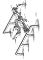
- Figure I depicts a high rail gantry tape laying machine 10 wherein a tape laying head I l is transported coordinately on side rails 12, 13 and transverse gantry rails 14.
- a contoured tape laydown surface 15 is positionable with respect to the tape laying head I to form laminated composite structures.
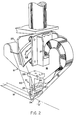
- FIG. 2 The close-up perspective view of Figure 2 illustrates the tape laying head 11 as comprising in part, a main frame 16 supporting a tape supply reel 17 carrying a tape structure 18 comprising a filamentous composite tape 19 and a backing paper tape 20.
- the tape structure 18 is trained across a tape presser assembly 21 and the backing paper tape 20 is accumulated on a take- up reel 22.
- the tape laying head main frame 16 is rotatable on a circular way system 23 about the tape laying path axial "A".
- a presser shoe assembly 24 is depicted as part of the tape presser assembly 21 and, while the shoe assembly 24 may be carried in a variety of shoe support structures, the preferred embodiment herein illustrates the shoe assembly 24 as being carried in a cam plate 25 forming a yoke which also is rotatable about axis A, independent of the tape head main frame rotation.
- the cam plate rotation is effected by a circular track 26, concentric with the circular way system 23, supported on cam followers 27 in the T-block 28 of the presser member assembly 21.
- Figure 3 depicts in diagrammatic forms a force divider 29 of a tape presser assembly 30 consisting elementally of a presser frame 31 upon which a downward force, F 1 , is directed.
- the vertical leg 32 of the presser frame 31 has a horizontal axle 33 and intergral ball element 34.
- a solid member 35 has a curved raceway 36 in contact with the bottom of the ball element 34, and a pair of spaced outer ball segments 37, 38 are provided on the solid member 35.
- the outer race elements 39, 40 are adapted to the two spaced- apart ball segments 37, 38 and from simple mechanics it can therefore be shown that reaction toads on the outer race elements 39, 49 may be designated as F 2 and F 3 , wherein F 1 equals F 2 plus F 3 .
- the respective values of F 2 and F 3 are dependent upon the respective spacings from the application point of force F 1 .
- Figure 4a depicts, in diagrammatic form, a structural embodiment of the force divider 29 of Figure 3 in a tape presser assembly 41, having the outer raceways 39a, 40a being completely circular about spherical ball segments 37a, 38a, and joined together by an elastometric sleeve 42.
- the biasing mechanism 43 herein depicted is a circular 44 ring having spring supports 45 about the central axle 33 to provide for a normal or home position of the assembly when the distortion forces of the presser member are removed.
- Figure 4b is an alternate embodiment of the elements of Figure 4a, wherein a plurality of like assemblies are employed, banded together by a common elastomeric sleeve 42a.
- the outboard assembly serves as the restorative biasing element 43a, and the assembly in its undistorted state, will return to the normal or home position depicted.
- a simplified structure for a wheel steering mechanism 46 such as might be employed in automobiles, is depicted in Figures 5, 6, and 7 wherein a pair of parallel wheels 47, 48 are arranged for rotation about wheel axes 47a, 48a, of rotation which are parallel to a surface 49 in contact with the wheels 47, 48. Knuckles axes 47b, 48b are arranged in a vertical attitude so that the wheels 47, 48 may be swiveled on the contact surface 49.
- Figure 5a depicts a side view of the wheels of Figure 5, wherein the (previously) vertical knuckle axes 47b, 48b have been titled backward through an angle alpha to increase stability of the mechanism 46 when moving in the direction of the broad arrow.
- the condition depicted is referred to as negative caster. If the knuckle axis 47b is tilted to a forward angle, the resulting condition would be positive coster.
- Figure 6a depicts the wheels of Figure 6 wherein the wheels 47, 48 are closer together at the bottom thereby tilting the knuckle axes 47b, 48b through an included angle alpha.
- the condition depicted is referred to as positive camber, and angle beta is referred to as the comber angle.
- Figure 7a depicts the plan view of Figure 7 with the wheels 47, 48 swivled about the vertical knuckle axes 47, 48b so that the wheels 47, 48 are closer together at the front, i.e., the wheels 47, 48 converge through an included angle gamma to a forward point.
- the condition depicted is referred to as toe-in.
- the wheels 47, 48 are swiveled about their respective vertical axes 47b, 48b so that they diverge at the forward end, the condition is referred to as toe-out.
- Figure 8 is an elevational section through the cam plate 25, or yoke, and presser shoe assembly 24 of Figure 2.
- the yoke 25 has a large, downwardly opening slot 50 machined into its bottom surface 51, resulting in right and left yoke legs 52, 53.
- the legs 52, 53 have in-line bores 54 and side set screws 55 for captivating an axle assembly 56.
- the axle assembly 56 consits of a central shaft 57 having an enlarged centre section 58 and smaller threaded stud portions 59 extending from each end.
- a bored ball segment 60 is received on each stud portion 59 and a cylindrical sleeve nut 61 is finally received on the stud portion 59 to clamp the ball segments 60 and central shaft 57 into a unitary axle assembly 56.
- the axle assembly 56 is retained by the side set screws 55 so that the assembly 56 does not rotate. Since the shoe assembly 24 is essentially symmetrical about a vertical central axis 62, which intersects axis "A" on the tape loydown surface 15, only the left-hand portion will be described in detail, the right-hand portion being a mirror image.
- the shoe assembly 24 has an inboard shoe member 63 and an outboard shoe member 64 spaced by loose fitting plates 65, 66 having the same cross- section, i.e., as shown in Figure 9.
- the members 63, 64 are tied to one another by a common sheet or strip 67 of elastomeric material, for example, silicon rubber, which is held to each member 64, 64 by a buttonhead screw 68 received through a clamping washer 69.
- the strip 67 may be covered with an outer sheet of low-friction material, such as "Telflon", a DuPont Company Trade Mark for polytetraflouroethylene (PTFE) plastic.
- the central ball segment 60 has an outer race 70 mounted thereon with a smooth slip fit, and the outer race 70 supports a tube 71 having a flange 72 at one end and a snap ring 73 at the other which, in turn, serve to retain a pair of outer ball segments 74 on the tube 71.
- the ball segments 74 are held to a fixed centre distance by a washer 75 received axially therebetween.
- the large bores 76, 77 at either end of the tube 71 permit the tube to swivel freely on the inner ball segment 60.
- the outer ball segments 74 each have an outer race 78 running with a smooth slip fit secured in respective inboard and outboard shoe members 63, 64.
- the upper slot face 79 has accurate vertical bores 80 machined inline with the centrelines 74a of the outer ball segments 74 when the assembly 24 is in an unstressed or undistorted state.
- the shoe members 63, 64 have vertical bores 81 in their top surfaces inline with the s!ot bores 80 andknuckle pins 82 serve to link the yoke 35 and shoe members 63, 64.
- the knuckle pin 82 is tightly fitted in the segment member 63, 64 having a flange 83 located against the tip surface 63a, 64a, and a top knuckle pin portion has a full diameter circular contact line 84 with back tapers 85, 86 machined from the line 84 to provide relief for the pin 82 in the bore 80.
- the pin 82 may smoothly translate in a vertical direction, axially with the slot bore 80, and the pin 82 may also be swiveled universally in a knuckling action with the bore 80.
- the inboard and outboard shoe members 63, 64 may toe-in or toe-out, owing to the rotatability of the knuckle pin 82 and the distortion of the elastomer which bonds the pieces together.
- the tube 71 may be swiveled into the plane of the paper as viewed by the reader, so that one outer ball segment 74 will come forward while the other moves in a rearward direction, thus creating alternating conditions of generally positive and negative caster.
- the shoe assembly 25 provides for a flexible mechanism banded together by undistorted elastomeric strip 67.
- Outer retaining plates 87 are secured with screws 88 to the outboard shoe members 64 to assist in keeping the elastomeric strip 67 in position.
- roller assembly 89 depicted in the elevational section of Figure 10 and side view of Figure I I.
- the axle assembly 56 is the same as that depicted in Figure 8, including the ball segments 60, 74 and respective races 70, 78. Again, the assembly 89 is symmetrically a mirror image about the vertical centreline 62.
- a cylindrical, flanged roller ring 90 is received on the outboard outer race 78.
- the inboard race 78 supports an unflanged roller ring 91.
- Loose-fitting spacer rings 92, 93 serve to separate the roller rings 90, 91 and an elastomeric sleeve 94 is received over the entire assembly and retained therewith by moulded internal grooves 95 received on the flanges 96 of the outboard roller rings 90.
- the assembly 89 in its undistorted state thus comprises a cylindrical roller journalled on the axle assembly 56.
- the assembly 89 has great universal swivel movement owing to combinations of both the tube 71 on the inner ball segment 60 and the outer roller rings 90, 91 on the outer ball segments 74.
- the yieldoble sleeve 94 may be distorted to accommodate various surface contours, and the ball segments 60, 74 will accommodate adaptation of the solid members of assembly 89 to the surface contours. Additionally, the ball segments 60, 74 will transmit the application force from the tape head I through the force dividing characteristics as explained in Figures 3, 4a and 4b.
- the section depicted in diagrammatic forms in Figure 12 shows exemplary main or parallel contour surfaces 15c, b joined by a slope 15c of approximately one in five.
- the axle assembly 56 is canted to approximate the slope 15c, while the force dividing ball segments of the roller assembly 89 permit the sleeve to be distorted to fit adjacent contour surface 15a, b, c.
- the elastomeric sleeve will tend to bias the entire assembly back to the cylindrical form depicted in Figure 10.
Landscapes
- Engineering & Computer Science (AREA)
- Robotics (AREA)
- Chemical & Material Sciences (AREA)
- Composite Materials (AREA)
- Mechanical Engineering (AREA)
- Sewing Machines And Sewing (AREA)
- Laminated Bodies (AREA)
- Moulding By Coating Moulds (AREA)
- Lining Or Joining Of Plastics Or The Like (AREA)
- Tyre Moulding (AREA)
Applications Claiming Priority (2)
| Application Number | Priority Date | Filing Date | Title |
|---|---|---|---|
| US740708 | 1985-06-03 | ||
| US06/740,708 US4601775A (en) | 1985-06-03 | 1985-06-03 | Compliant presser member for composite tape laying machine |
Publications (3)
| Publication Number | Publication Date |
|---|---|
| EP0204249A2 true EP0204249A2 (fr) | 1986-12-10 |
| EP0204249A3 EP0204249A3 (en) | 1987-07-22 |
| EP0204249B1 EP0204249B1 (fr) | 1990-05-09 |
Family
ID=24977710
Family Applications (1)
| Application Number | Title | Priority Date | Filing Date |
|---|---|---|---|
| EP86107170A Expired - Lifetime EP0204249B1 (fr) | 1985-06-03 | 1986-05-27 | Machine d'application de rubans et organe presseur pour les rubans dans les machines d'application de rubans |
Country Status (4)
| Country | Link |
|---|---|
| US (1) | US4601775A (fr) |
| EP (1) | EP0204249B1 (fr) |
| JP (1) | JPH069874B2 (fr) |
| DE (1) | DE3670972D1 (fr) |
Cited By (3)
| Publication number | Priority date | Publication date | Assignee | Title |
|---|---|---|---|---|
| FR2635714A1 (fr) * | 1988-08-26 | 1990-03-02 | Brisard Machines Outils | Dispositif de nappage pour la mise en place automatique d'une nappe de fibres sur un moule et machine comportant un tel dispositif |
| EP0361828A3 (en) * | 1988-09-26 | 1990-06-27 | Cincinnati Milacron Inc. | Fiber placement machine, and fiber placement head |
| FR2650529A1 (fr) * | 1989-08-03 | 1991-02-08 | Aerospatiale | Dispositif applicateur pour machine de nappage au moyen de ruban de matiere composite |
Families Citing this family (30)
| Publication number | Priority date | Publication date | Assignee | Title |
|---|---|---|---|---|
| US4696707A (en) * | 1987-08-18 | 1987-09-29 | The Ingersoll Milling Machine Company | Composite tape placement apparatus with natural path generation means |
| US4750965A (en) * | 1986-03-28 | 1988-06-14 | The Ingersoll Milling Machine Company | Adaptive control for tape laying head having natural path generation |
| US4915771A (en) * | 1987-10-08 | 1990-04-10 | The Boeing Company | Segmented tape shoe |
| EP0334123B1 (fr) * | 1988-03-25 | 1993-08-11 | Akechi Yano | Rouleau avec un axe courbé |
| JPH0725145B2 (ja) * | 1988-05-24 | 1995-03-22 | 新日本工機株式会社 | テープの自動貼付装置におけるテープの進行方向制御方法 |
| US4872619A (en) * | 1988-11-02 | 1989-10-10 | Cincinnati Milacron Inc. | Serco driven redirect roller apparatus for fiber placement machine |
| US4877193A (en) * | 1988-08-25 | 1989-10-31 | Cincinnati Milacron Inc. | Redirect roller apparatus for fiber placement machine |
| US4943338A (en) * | 1988-09-26 | 1990-07-24 | Cincinnati Milacron Inc. | Multi-tow fiber placement machine with full band width clamp, cut, and restart capability |
| US4954204A (en) * | 1988-11-25 | 1990-09-04 | Cincinnati Milacron Inc. | Presser member for contoured surfaces |
| DE3900156A1 (de) * | 1989-01-04 | 1990-07-05 | Czewo Plast Kunststofftech | Vorrichtung zum auftragen eines klebstoffilms |
| US5015326A (en) * | 1989-05-08 | 1991-05-14 | The Boeing Company | Compliant tape dispensing and compacting head |
| GB9312520D0 (en) * | 1993-06-17 | 1993-08-04 | Gillette Co | Correction tape dispenser |
| US5454897A (en) * | 1994-05-02 | 1995-10-03 | Cincinnati Milacron Inc. | Presser member for fiber laying machine |
| USD473642S1 (en) * | 2001-03-12 | 2003-04-22 | Johnson & Johnson Industria E Comercio Ltda | Hygienic napkin |
| US7004219B2 (en) * | 2002-10-11 | 2006-02-28 | The Boeing Company | Roller for automated fabric layup |
| US7810539B2 (en) * | 2005-08-25 | 2010-10-12 | Ingersoll Machine Tools, Inc. | Compaction roller for a fiber placement machine |
| US20080093026A1 (en) * | 2006-10-24 | 2008-04-24 | Niko Naumann | Device for pressing a tape |
| US7717151B2 (en) * | 2007-11-29 | 2010-05-18 | Spirit Aerosystems, Inc. | Material placement method and apparatus |
| US7591294B2 (en) * | 2007-11-29 | 2009-09-22 | Spirit Aerosystems, Inc. | Material placement method and apparatus |
| US8206277B2 (en) * | 2008-04-30 | 2012-06-26 | Hewlett-Packard Development Company, L.P. | Idler roller assembly having a roller and a shaft the roller being formed such that it remains parallel to contacted media despite deflection of the shaft |
| DE102009009186B4 (de) | 2009-02-16 | 2011-04-21 | Airbus Operations Gmbh | Anpressvorrichtung zum Anpressen von faserverstärkten thermoplastischen Materialien und Faseranordnungsvorrichtung |
| FR2982792B1 (fr) * | 2011-11-23 | 2013-11-29 | Eurocopter France | Tete de depose d'un ruban de fibres impregnees, et dispositif de placement d'un tel ruban |
| TWI464070B (zh) * | 2011-12-16 | 2014-12-11 | Cal Comp Electronics & Comm Co | 從動單元及饋紙裝置 |
| EP2730385A1 (fr) * | 2012-11-09 | 2014-05-14 | Eurocopter Deutschland GmbH | Système de contrôle thermique pour rouleau de consolidation |
| US9314974B2 (en) * | 2013-01-07 | 2016-04-19 | The Boeing Company | Method and apparatus for fabricating contoured laminate structures |
| US10828846B2 (en) * | 2013-01-07 | 2020-11-10 | The Boeing Company | Method and apparatus for fabricating contoured laminate structures |
| DE102016103484A1 (de) * | 2016-02-26 | 2017-08-31 | Deutsches Zentrum für Luft- und Raumfahrt e.V. | Faserlegekopf zum Legen von Faserhalbzeugprofilen, Faserlegeanlage sowie Verfahren hierzu |
| US10391723B2 (en) | 2017-08-31 | 2019-08-27 | The Boeing Company | Rotary compaction tool |
| US20240326353A1 (en) * | 2022-03-03 | 2024-10-03 | Massivit 3D Printing Technologies Ltd. | A Dynamic Configurable Digital Mold |
| GB2622647A (en) * | 2022-09-20 | 2024-03-27 | Icomat Ltd | A tape laying head |
Family Cites Families (9)
| Publication number | Priority date | Publication date | Assignee | Title |
|---|---|---|---|---|
| DE32344C (de) * | sächsische Stickmaschinenfabrik (Albert Voigt) in Kappel b. Chemnitz | Apparat zur Zuführung der Hölzer an Säge- und Hobelmaschinen | ||
| US1717372A (en) * | 1927-07-20 | 1929-06-18 | United Shoe Machinery Corp | Leveling machine |
| US2446211A (en) * | 1947-06-09 | 1948-08-03 | Louis D Clark | Ring roll |
| US2593158A (en) * | 1950-02-23 | 1952-04-15 | United States Steel Corp | Apparatus for positioning strip |
| DE1099717B (de) * | 1956-04-24 | 1961-02-16 | Lutz Kg Eugen | Vorschubapparat mit Vorschubrollen |
| US3037449A (en) * | 1958-01-21 | 1962-06-05 | Carl Allers Ets | Ductor roller for use in distribution roller systems for liquid and semiliquid substances |
| DE2216784C3 (de) * | 1972-04-07 | 1980-10-16 | Rauhut Kg Rohr- Und Strohmattenfabrik, 2831 Bramstedt | Laminierwalze zur Herstellung von glasfaserverstärkten Kunstharz-Formteilen mit ebener oder gekrümmter Oberfläche |
| US4460433A (en) * | 1982-11-04 | 1984-07-17 | Boyd Walter K | Pressure roller for roofing machines |
| FR2539122B1 (fr) * | 1983-01-10 | 1986-10-24 | Dassault Avions | Machine pour revetir une surface quelconque avec un materiau composite de fibres et de resine |
-
1985
- 1985-06-03 US US06/740,708 patent/US4601775A/en not_active Expired - Lifetime
-
1986
- 1986-05-27 DE DE8686107170T patent/DE3670972D1/de not_active Expired - Fee Related
- 1986-05-27 EP EP86107170A patent/EP0204249B1/fr not_active Expired - Lifetime
- 1986-06-02 JP JP61127844A patent/JPH069874B2/ja not_active Expired - Lifetime
Cited By (8)
| Publication number | Priority date | Publication date | Assignee | Title |
|---|---|---|---|---|
| FR2635714A1 (fr) * | 1988-08-26 | 1990-03-02 | Brisard Machines Outils | Dispositif de nappage pour la mise en place automatique d'une nappe de fibres sur un moule et machine comportant un tel dispositif |
| EP0361997A1 (fr) * | 1988-08-26 | 1990-04-04 | Brisard Machines-Outils | Dispositif de nappage pour la mise en place automatique d'une nappe de fibres sur un moule |
| US5074948A (en) * | 1988-08-26 | 1991-12-24 | Brisard Machines Outils | Lay-up device for automatic positioning of a web of fibers on a mold |
| WO1993013931A1 (fr) * | 1988-08-26 | 1993-07-22 | Greffioz Andre | Dispositif de nappage pour la mise en place automatique d'une nappe de fibres sur un moule |
| EP0361828A3 (en) * | 1988-09-26 | 1990-06-27 | Cincinnati Milacron Inc. | Fiber placement machine, and fiber placement head |
| FR2650529A1 (fr) * | 1989-08-03 | 1991-02-08 | Aerospatiale | Dispositif applicateur pour machine de nappage au moyen de ruban de matiere composite |
| EP0411995A3 (en) * | 1989-08-03 | 1991-08-28 | Aerospatiale Societe Nationale Industrielle Societe Anonyme Dite: | Applicator-head for composite tape laying machine |
| US5176785A (en) * | 1989-08-03 | 1993-01-05 | Societe Anonyme Dite: Aerospatiale Societe Nationale Industrielle Ayant Son Siege Social | Applicator device for a laying machine using a composite material tape |
Also Published As
| Publication number | Publication date |
|---|---|
| EP0204249B1 (fr) | 1990-05-09 |
| JPS6237161A (ja) | 1987-02-18 |
| EP0204249A3 (en) | 1987-07-22 |
| US4601775A (en) | 1986-07-22 |
| DE3670972D1 (de) | 1990-06-13 |
| JPH069874B2 (ja) | 1994-02-09 |
Similar Documents
| Publication | Publication Date | Title |
|---|---|---|
| EP0204249A2 (fr) | Machine d'application de rubans et organe presseur pour les rubans dans les machines d'application de rubans | |
| EP0361828B1 (fr) | Machine pour l'application de fibres et tête d'application de fibres | |
| JP3018520U (ja) | 繊維付設機用押え部材 | |
| US4943338A (en) | Multi-tow fiber placement machine with full band width clamp, cut, and restart capability | |
| US4627886A (en) | Composite tape laying machine with pivoting presser member | |
| US6105899A (en) | Web tension equalizing roll and tracking apparatus | |
| US4877193A (en) | Redirect roller apparatus for fiber placement machine | |
| US4178664A (en) | Roller with replaceable sleeve | |
| DE69836585T2 (de) | Rollschuh | |
| DE2165140C2 (de) | Vorrichtung zur Führung und Lagerung eines bewegten, endlosen flexiblen Bandes auf mindestens zwei Rollen | |
| CA2592644A1 (fr) | Ensemble destine a fournir une souplesse a un systeme de lame | |
| ATE209114T1 (de) | Gummigefedertes schienenrad | |
| JPH10513426A (ja) | プレフォーム支持装置 | |
| GB1589106A (en) | Apparatus for removing a cylinder from a screw extruder | |
| US4967440A (en) | Rotary cloth roll assembly | |
| US5984767A (en) | Assembly using an abrasive strip to machine a cylindrical bearing surface of a workpiece | |
| WO1992018210A2 (fr) | Article de sport dirigeable par deplacement du poids du corps et systeme de roulettes dirigeable pour un tel article | |
| EP0250673B1 (fr) | Machine d'application de bandes composites avec un organe presseur pivotant | |
| CA1142350A (fr) | Ensemble de plaques a mouvements translatoire et rotatif pour le redressement des roues de vehicules | |
| JPS5845020A (ja) | テ−プ自動貼付用押付ロ−ル装置 | |
| JPH0221192Y2 (fr) | ||
| RU2079386C1 (ru) | Роликовая волока | |
| JPS6277620U (fr) | ||
| DE60104624T2 (de) | Vorrichtung zum Laserschweissen von Längsverstärkungselementen auf Aluminiumplatten | |
| CA2107835C (fr) | Dispositif pour liaisonner les plis d'une trame de papier ou de materiaux analogue |
Legal Events
| Date | Code | Title | Description |
|---|---|---|---|
| PUAI | Public reference made under article 153(3) epc to a published international application that has entered the european phase |
Free format text: ORIGINAL CODE: 0009012 |
|
| AK | Designated contracting states |
Kind code of ref document: A2 Designated state(s): CH DE FR GB IT LI SE |
|
| PUAL | Search report despatched |
Free format text: ORIGINAL CODE: 0009013 |
|
| AK | Designated contracting states |
Kind code of ref document: A3 Designated state(s): CH DE FR GB IT LI SE |
|
| 17P | Request for examination filed |
Effective date: 19870914 |
|
| 17Q | First examination report despatched |
Effective date: 19871203 |
|
| GRAA | (expected) grant |
Free format text: ORIGINAL CODE: 0009210 |
|
| AK | Designated contracting states |
Kind code of ref document: B1 Designated state(s): CH DE FR GB IT LI SE |
|
| ITF | It: translation for a ep patent filed | ||
| REF | Corresponds to: |
Ref document number: 3670972 Country of ref document: DE Date of ref document: 19900613 |
|
| ET | Fr: translation filed | ||
| PLBE | No opposition filed within time limit |
Free format text: ORIGINAL CODE: 0009261 |
|
| STAA | Information on the status of an ep patent application or granted ep patent |
Free format text: STATUS: NO OPPOSITION FILED WITHIN TIME LIMIT |
|
| 26N | No opposition filed | ||
| ITTA | It: last paid annual fee | ||
| PGFP | Annual fee paid to national office [announced via postgrant information from national office to epo] |
Ref country code: SE Payment date: 19930517 Year of fee payment: 8 |
|
| PGFP | Annual fee paid to national office [announced via postgrant information from national office to epo] |
Ref country code: CH Payment date: 19930526 Year of fee payment: 8 |
|
| PG25 | Lapsed in a contracting state [announced via postgrant information from national office to epo] |
Ref country code: SE Effective date: 19940528 |
|
| PG25 | Lapsed in a contracting state [announced via postgrant information from national office to epo] |
Ref country code: LI Effective date: 19940531 Ref country code: CH Effective date: 19940531 |
|
| EUG | Se: european patent has lapsed |
Ref document number: 86107170.2 Effective date: 19941210 |
|
| REG | Reference to a national code |
Ref country code: CH Ref legal event code: PL |
|
| EUG | Se: european patent has lapsed |
Ref document number: 86107170.2 |
|
| PGFP | Annual fee paid to national office [announced via postgrant information from national office to epo] |
Ref country code: FR Payment date: 19950510 Year of fee payment: 10 |
|
| PGFP | Annual fee paid to national office [announced via postgrant information from national office to epo] |
Ref country code: GB Payment date: 19950516 Year of fee payment: 10 |
|
| PGFP | Annual fee paid to national office [announced via postgrant information from national office to epo] |
Ref country code: DE Payment date: 19950523 Year of fee payment: 10 |
|
| PG25 | Lapsed in a contracting state [announced via postgrant information from national office to epo] |
Ref country code: GB Effective date: 19960527 |
|
| GBPC | Gb: european patent ceased through non-payment of renewal fee |
Effective date: 19960527 |
|
| PG25 | Lapsed in a contracting state [announced via postgrant information from national office to epo] |
Ref country code: FR Effective date: 19970131 |
|
| PG25 | Lapsed in a contracting state [announced via postgrant information from national office to epo] |
Ref country code: DE Effective date: 19970201 |
|
| REG | Reference to a national code |
Ref country code: FR Ref legal event code: ST |
|
| PG25 | Lapsed in a contracting state [announced via postgrant information from national office to epo] |
Ref country code: IT Free format text: LAPSE BECAUSE OF NON-PAYMENT OF DUE FEES Effective date: 20050527 |