EP0204569A2 - Nichtharmonische NMR-Spin-Echo-Bildgebung - Google Patents
Nichtharmonische NMR-Spin-Echo-Bildgebung Download PDFInfo
- Publication number
- EP0204569A2 EP0204569A2 EP86304287A EP86304287A EP0204569A2 EP 0204569 A2 EP0204569 A2 EP 0204569A2 EP 86304287 A EP86304287 A EP 86304287A EP 86304287 A EP86304287 A EP 86304287A EP 0204569 A2 EP0204569 A2 EP 0204569A2
- Authority
- EP
- European Patent Office
- Prior art keywords
- signals
- spin echo
- radio frequency
- frequency signal
- signal
- Prior art date
- Legal status (The legal status is an assumption and is not a legal conclusion. Google has not performed a legal analysis and makes no representation as to the accuracy of the status listed.)
- Granted
Links
- 238000003384 imaging method Methods 0.000 title description 8
- 238000005481 NMR spectroscopy Methods 0.000 claims abstract description 29
- 230000001939 inductive effect Effects 0.000 claims abstract 2
- 230000003068 static effect Effects 0.000 claims abstract 2
- 230000003252 repetitive effect Effects 0.000 claims 2
- 238000000034 method Methods 0.000 description 17
- 230000005284 excitation Effects 0.000 description 13
- 238000001208 nuclear magnetic resonance pulse sequence Methods 0.000 description 9
- 238000002592 echocardiography Methods 0.000 description 6
- 230000000694 effects Effects 0.000 description 6
- 230000005540 biological transmission Effects 0.000 description 4
- 230000004075 alteration Effects 0.000 description 3
- 238000010586 diagram Methods 0.000 description 3
- 238000010438 heat treatment Methods 0.000 description 3
- 238000004519 manufacturing process Methods 0.000 description 3
- 230000015572 biosynthetic process Effects 0.000 description 2
- 238000012512 characterization method Methods 0.000 description 2
- 230000001934 delay Effects 0.000 description 2
- 230000001066 destructive effect Effects 0.000 description 2
- 238000001514 detection method Methods 0.000 description 2
- 238000011161 development Methods 0.000 description 2
- 238000002474 experimental method Methods 0.000 description 2
- 238000012545 processing Methods 0.000 description 2
- 238000011896 sensitive detection Methods 0.000 description 2
- 238000012163 sequencing technique Methods 0.000 description 2
- 238000009825 accumulation Methods 0.000 description 1
- 238000010276 construction Methods 0.000 description 1
- 238000013480 data collection Methods 0.000 description 1
- 238000003745 diagnosis Methods 0.000 description 1
- 230000006870 function Effects 0.000 description 1
- 230000006698 induction Effects 0.000 description 1
- 238000002360 preparation method Methods 0.000 description 1
- 230000035945 sensitivity Effects 0.000 description 1
- 238000000264 spin echo pulse sequence Methods 0.000 description 1
- 238000003860 storage Methods 0.000 description 1
- 238000012546 transfer Methods 0.000 description 1
Images



Classifications
-
- G—PHYSICS
- G01—MEASURING; TESTING
- G01R—MEASURING ELECTRIC VARIABLES; MEASURING MAGNETIC VARIABLES
- G01R33/00—Arrangements or instruments for measuring magnetic variables
- G01R33/20—Arrangements or instruments for measuring magnetic variables involving magnetic resonance
- G01R33/44—Arrangements or instruments for measuring magnetic variables involving magnetic resonance using nuclear magnetic resonance [NMR]
- G01R33/48—NMR imaging systems
- G01R33/4818—MR characterised by data acquisition along a specific k-space trajectory or by the temporal order of k-space coverage, e.g. centric or segmented coverage of k-space
- G01R33/482—MR characterised by data acquisition along a specific k-space trajectory or by the temporal order of k-space coverage, e.g. centric or segmented coverage of k-space using a Cartesian trajectory
-
- G—PHYSICS
- G01—MEASURING; TESTING
- G01R—MEASURING ELECTRIC VARIABLES; MEASURING MAGNETIC VARIABLES
- G01R33/00—Arrangements or instruments for measuring magnetic variables
- G01R33/20—Arrangements or instruments for measuring magnetic variables involving magnetic resonance
- G01R33/44—Arrangements or instruments for measuring magnetic variables involving magnetic resonance using nuclear magnetic resonance [NMR]
- G01R33/48—NMR imaging systems
- G01R33/54—Signal processing systems, e.g. using pulse sequences ; Generation or control of pulse sequences; Operator console
- G01R33/56—Image enhancement or correction, e.g. subtraction or averaging techniques, e.g. improvement of signal-to-noise ratio and resolution
- G01R33/565—Correction of image distortions, e.g. due to magnetic field inhomogeneities
- G01R33/56554—Correction of image distortions, e.g. due to magnetic field inhomogeneities caused by acquiring plural, differently encoded echo signals after one RF excitation, e.g. correction for readout gradients of alternating polarity in EPI
Definitions
- This invention relates to nuclear magnetic resonance (NMR) imaging systems and, in particular, to techniques for acquiring NMR information signals with short and long spin echo delays.
- NMR nuclear magnetic resonance
- NMR imaging systems there are two general techniques for collecting NMR information signals.
- One is to detect the free induction decay (FID) signals which are present immediately following a radio frequency (RF) excitation pulse.
- FID free induction decay
- RF radio frequency
- the immediacy of the occurrence of these signals is advantageous in that it allows NMR information to be gathered quickly, which can shorten the time required to gather the desired information.
- their near proximity in time to the excitation pulses makes detection difficult, since residual effects of these pulses can interfere with accurate detection of the FID signals.
- switching from RF pulse transmission to FID signal reception becomes critical, especially when a common RF coil is used for both transmission and reception.
- a second technique for NMR information acquisition is the spin echo technique.
- the FID signals following the RF excitation pulses are ignored.
- a 180 degree inverting RF pulse is applied to refocus the previously excited spins.
- a spin echo signal is produced which resembles back-to-back FID signals.
- the spin echo signal may be detected at a time when RF pulse effects have substantially dissipated, making data collection less critical.
- numerous gradient fields can be applied to the subject being imaged to imbue the spin echo signals with greater information content.
- the successively occurring inverting RF pulses are applied at precisely timed. equal intervals after the RF excitation pulse. This results in the production of spin echo signals at regularly recurring time intervals, affording ease in timed signal acquisition.
- the present inventors have found that these techniques result in a complex form of harmonic signal distortion.
- Each regularly recurring spin echo signal will contain signal artifacts which are harmonically-related reflections of earlier applied and produced signals.
- these signals will contain artifact components resulting from any imperfections in the earlier applied RF pulses. A great deal of the contrast of these later spin echoes can become obscured by these artifact components.
- a technique for producing multiple spin echo signals following an initial excitation pulse is provided.
- a first inverting pulse is applied a given time interval following the initial excitation pulse, resulting in the formation of the usual first spin echo signal after passage of the given time interval.
- Information from this first spin echo signal may be used in the construction of an image of high signal to noise ratio.
- a second inverting pulse is applied. The tine interval between the initial excitation pulse and this second inverting pulse is not required to be harmonically related to the first given time interval. This results in the production of at least a second, later occurring spin echo signal which does not contain harmonically-related artifact components of the earlier pulses and spin echo signals.
- a plurality of spin echo signals are generally produced after the second inverting pulse at times which are functions of the given time interval and the time interval between the initial excitation pulse and the second inverting pulse.
- One of these spin echo signals is the desired, later occurring spin echo. and the others are unwanted.
- the close proximity in time of these pulses can cause the unwanted signals to interfere with the sensitive detection of the desired signal.
- the phases of the RF pulses are coordinated so that ones of the unwanted signal components will destructively interfere with each other and thereby be eliminated. An ease in the sensitive detection of the desired later occurring spin echo signal is thus afforded.
- the NMR techniques of the present invention may be performed by an NMR imaging system such as that shown in block diagram form in FIGURES 1 and 2.
- FIGURE 1 the transmission portion of an NMR imaging system is shown.
- a transmitter mixer 12 receives a signal F s , where F s is the transmitted radio frequency NMR signal, from a frequency synthesizer 10.
- the F s signal is heterodyned by the mixer to produce a modulated F signal, which is coupled by way of a controlled transmitter attenuator 14 to a transmitter amplifier 16.
- the transmitter mixer 12 and attenuator 14 are controlled by control signals provided by a pulse sequencer 20, which applies an RF enable signal to the mixer 12.
- the F s signal is amplified by the amplifier 16 and applied to the RF coil 24 in the magnet 30 in the form of a sequence of pulses formed under control of the pulse sequencer 20.
- the RF coil 24 applies the F s pulses to the subject being imaged.
- x, y. and z gradient coils 26. 28, and 29 are also located within the field of the magnet 30. These coils receive gradient control signals G x , G y , and G z from gradient signal amplifiers 22. The control signals are produced by the pulse sequencer 20.
- the NMR signals emitted by the nuclei of the material being imaged induce F s return signals in the RF coil 24. These return signals are coupled by way of an RF matching network 25 to a pre-amplifier 27, and on to a receiver attenuator 34 as shown in FIGURE 2.
- the received F s signals are amplified by an amplifier 36 and applied to quadrature phase detectors 42 and 44.
- the phase detectors receive two phase demodulating signals at respective 0° and 90° phase angles from a phase shifter 40. which receives an F s reference signal from the frequency synthesizer 10.
- the phase detectors 42 and 44 produce a channel A and a channel B signal. respectively.
- the baseband A and B signals are filtered by respective low pass filters 46 and 48, and the filtered signals are then sampled by respective analog to digital converters 50 and 52.
- the resultant channel A and channel B digital words are stored in the memory of a computer 60.
- the channel A and B digital words are then combined and transformed to the frequency domain by a Fourier transform array processor 62.
- the resultant image signals are assembled in an image format by an image processor 64, and the processed image is displayed on a video monitor 66.
- a multiple echo pulse sequence is shown in which he spin echoes are derived from a sequence of uniformly time-spaced 180° inverting pulses.
- a 90° pulse 70 is applied to the subject by the RF coil to excite a group of nuclei.
- a 180° pulse 72 is applied, resulting in the generation of a spin echo signal 72 at time 2t.
- the spin echo signal 72 exhibits good signal to noise characteristics, and may be used in combination with similarly acquired spin echo signals to produce a clearly defined image with good structural detail.
- a second 180° pulse 73 is applied, producing another spin echo signal 74 at time 4t.
- Another 180° pulse 75 at time 5t produces a third spin echo signal 76 at time 6t.
- a further 180° pulse 77 results in the development of the desired spin echo signal 78 at time ; 8t.
- the spin echo signal 78 exhibits poorer signal-to-noise characteristics than the previous signals. but has relatively high spin-spin relaxation contrast for the reconstruction of images with good tissue characterization.
- spin echo signal 72 contains one echo component. which is the refocused equivalent of the FID signal occurring immediately after the 90° pulse 70. FID signals occur after every RF pulse, but are not shown in FIGURE 3. Since the spin echo signal 72 contains only one echo component, there are no undesired artifacts associated with this signal.
- the second 180° pulse 73 produces four echo components.
- RF pulse delays of t and 3t for the 180° pulses 71 and 73 two of these components will coincide at time 4t.
- One of these signal components will contain phase-cancelling artifact components.
- spin echo signal components follow 180° pulse 75. of which five occur at time 6t, where the desired component also appears.
- the desired, later occurring spin echo signal 78 contains thirteen echo components which are overlapping in time.
- the number of echo components following in the n th 180° pulse may be expressed mathematically as:
- FIGURE 3 shows that five RF pulses must be applied in order to produce the desired later occurring spin echo signal 78. It is desirable to minimize RF heating by applying as few RF pulses as necessary to produce the wanted later occurring spin echo signal.
- a 90° RF excitation pulse 80 which exhibits a phase angle ⁇ 1 is applied initially. This pulse is followed at time t by a 180° RF inverting pulse 82 which exhibits a phase angle ⁇ 2 . At time 2t, which succeeds the inverting pulse 82 by the interval t, the first spin echo signal 83 is produced. As before, the first spin echo signal 83 may be used in the formation of an NMR image of good structural clarity.
- a second 180° pulse 84 with a phase angle e 3 is applied.
- This second inverting pulse results in the development of several spin echo signals at times which are reflections of the.earlier time intervals about the pulse 84 at time T.
- a first, undesired spin echo signal 85 occurs at time T+t. which is a reflection of the earlier t interval about time T.
- the desired, later occurring spin echo signal 86 occurs at time 2T-2t, a time after the inverting pulse 84 which is equal to the time interval by which spin echo signal 83 precedes the inverting pulse 84.
- This desired signal is followed by two other unwanted spin echo signals 87 and 89.
- Signal 87 follows the inverting pulse 84 by an interval 2T-t, the interval by which pulse 82 and its FID signal precedes the pulse 84.
- Spin echo signal 87 thus contains echo components derived from the FID signal of inverting pulse 82.
- spin echo signal 89 occurs at time 2T, and contains echo components derived from the FID signal of the 90° excitation pulse 80.
- Other advantages include less RF heating and less cumbersome data handling than the sequence of FIGURE 3.
- the most useful spin echo signals can be obtained without also acquiring intervening undesired signals, which otherwise occupy additional storage space and additional time to reconstruct unnecessary images and display, delete, or transfer to film.
- the inventive technique also overcomes the added sensitivity of desired signals to artifacts resulting from imperfections of the numerous RF pulses of the earlier technique.
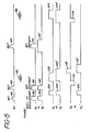
- FIGURE 5 shows the RF pulse sequence of FIGURE 4, together with the applied gradient signals G x , G y , and G for spatially identifying the spin echo signal components.
- the z direction gradient G is used for slice selection by its application coincident in time with the RF pulses.
- G pulses 90 and 92 are applied together with RF pulses 80 and 82, respectively, and G pulse 94 is applied coincident with the second 180° pulse 84.
- G z ' pulse 94' is seen to start earlier in time and end later in time relative to RF pulse 84 as compared to G z pulse 94.
- This broader pulse 94' allows the G z gradient field at the time of RF pulse 84 some initial time to stabilize before RF pulse 84 begins, and the time at the end of pulse 94' helps dephase the FID signal resulting from any tip angle missettings caused by RF pulse 84.
- the broader pulse 94' also causes the Z direction rephasing time of the phase destructive spin echo signal next occurring (signal 85 in FIGURE 4) to shift in time away from the desired signal 86 and toward the time of the 180° pulse 84.
- the G x pulses provide spatial frequency encoding in the x direction.
- a first G x pulse 100 is applied during the time interval between RF pulses 80 and 82.
- G x pulses 10 2 and 104 are "read" pulses, applied during the times that the desired spin echo signals are acquired, digitized and sent to the computer memory.
- read pulse 104' is turned on for a time interval preceding the occurrence of spin echo signal 86.
- the early portion of G x pulse 104' helps to dephase FID signals resulting from any misadjustment of RF pulse 84. It also helps cause the phase destructive echo signal 85 (see FIGURE 4) to rephase earlier in time and further away from the desired spin echosignal 86.
- the latter extension of G x ' pulse 102' is required to balance the early turnon of pulse 104'.
- the G pulses provide spatial phase encoding in the y direction. Ones of these pulses are generally varied in amplitude from one sequence to the next for subsequent Fourier processing of the received spin echo signals.
- a first G y pulse 110 is applied after 180° pulse 82 and before the first spin echo signal 83 is acquired.
- a second G y pulse 112 is applied following spin echo signal 83, thereby reversing the effect of G y pulse 110 in preparation for phase encoding for the later occurring spin echo signal 86.
- a G y pulse l14 provides phase encoding for the later occurring spin echo signal 86.
- An alternative G y pulse sequence. G y ' is also shown. In this sequence, a first G ' pulse 120 provides phase encoding for spin echo signal 83.
- Pulse 120 is of opposite polarity to pulse 110 because pulse 120 precedes the RF inverting pulse 82.
- G ' pulse 112' follows spin echo signal 83 and is longer than pulse 112 to both cancel the effect of pulse 120 and provide phase encoding for later spin echo signal 86.
- Pulse 112' is of opposite polarity to pulse 114 because pulse 112' precedes the second RF inverting pulse 84.
- phase sequencing of the RF pulses may be selected so as to eliminate ones of the undesired spin echo signals from an accumulation of received spin echo signals. This phase sequencing and its effects are illustrated in FIGURE 6.
- the RF pulses are applied to produce spin echo signals 83 and 85-89.
- the RF pulses 80, 82, and 84 exhibit phase angles of 0°, 90° and 90°, respectively during this first sequence.
- the pulses 80. 82 and 84 exhibit phase angles of 0°, 270°, and 90°, respectively (or, alternatively. 180°. 90°. and 270°, respectively).
- the effect of this phase alteration from the first to the second sequence is to cause ones of the spin echo signals of the second sequence to exhibit new phases. It may be seen that spin echo signal 83' of the second sequence is in phase with previously acquired spin echo signal 83. These two signals may be combined during processing. affording constructive signal enhancement.
- the RF pulse phase alteration is seen to cause spin echo signals 86' and 89' to exhibit the same phases as corresponding signals 86 and 89 of the first sequence.
- the desired, later occurring spin echo signals 86 and 86' will enhance one another.
- spin echo signals 85' and 87' are seen to have undergone a phase alteration.
- these signals will cancel one another.
- these cancelling signals are the unwanted signal components on either side of the desired signals 86 and 86'. This cancellation will thus leave an artifact-free desired signal and result in improved signal to noise characteristics of the combined signals 86 and 86'.
Landscapes
- Physics & Mathematics (AREA)
- General Physics & Mathematics (AREA)
- High Energy & Nuclear Physics (AREA)
- Condensed Matter Physics & Semiconductors (AREA)
- Nuclear Medicine, Radiotherapy & Molecular Imaging (AREA)
- Radiology & Medical Imaging (AREA)
- Engineering & Computer Science (AREA)
- Signal Processing (AREA)
- General Health & Medical Sciences (AREA)
- Health & Medical Sciences (AREA)
- Magnetic Resonance Imaging Apparatus (AREA)
- Transforming Light Signals Into Electric Signals (AREA)
- Cable Transmission Systems, Equalization Of Radio And Reduction Of Echo (AREA)
- Ultra Sonic Daignosis Equipment (AREA)
Priority Applications (1)
| Application Number | Priority Date | Filing Date | Title |
|---|---|---|---|
| AT86304287T ATE64472T1 (de) | 1985-06-06 | 1986-06-05 | Nichtharmonische nmr-spin-echo-bildgebung. |
Applications Claiming Priority (2)
| Application Number | Priority Date | Filing Date | Title |
|---|---|---|---|
| US06/742,161 US4695800A (en) | 1985-06-06 | 1985-06-06 | Non harmonic NMR spin echo imaging |
| US742161 | 1985-06-06 |
Publications (3)
| Publication Number | Publication Date |
|---|---|
| EP0204569A2 true EP0204569A2 (de) | 1986-12-10 |
| EP0204569A3 EP0204569A3 (en) | 1988-03-09 |
| EP0204569B1 EP0204569B1 (de) | 1991-06-12 |
Family
ID=24983723
Family Applications (1)
| Application Number | Title | Priority Date | Filing Date |
|---|---|---|---|
| EP86304287A Expired - Lifetime EP0204569B1 (de) | 1985-06-06 | 1986-06-05 | Nichtharmonische NMR-Spin-Echo-Bildgebung |
Country Status (5)
| Country | Link |
|---|---|
| US (1) | US4695800A (de) |
| EP (1) | EP0204569B1 (de) |
| JP (1) | JP2641426B2 (de) |
| AT (1) | ATE64472T1 (de) |
| DE (1) | DE3679719D1 (de) |
Cited By (3)
| Publication number | Priority date | Publication date | Assignee | Title |
|---|---|---|---|---|
| EP0283058A1 (de) * | 1987-02-04 | 1988-09-21 | Koninklijke Philips Electronics N.V. | Verfahren und Vorrichtung zur Unterdrückung der kohärenten Interferenzeffekte von kernmagnetischen Resonanzsignalen |
| US5726569A (en) * | 1995-03-30 | 1998-03-10 | Siemens Aktiengesellschaft | Method and apparatus for acquiring image data in a nuclear magnetic resonance tomography system |
| US6208136B1 (en) | 1995-02-24 | 2001-03-27 | Btg International Limited | Method of and apparatus for nuclear quadrupole resonance testing a sample, and pulse sequence for exciting nuclear quadrupole resonance |
Families Citing this family (7)
| Publication number | Priority date | Publication date | Assignee | Title |
|---|---|---|---|---|
| JP2735191B2 (ja) * | 1987-07-22 | 1998-04-02 | 株式会社東芝 | 磁気共鳴イメージング装置 |
| US5144236A (en) * | 1990-08-17 | 1992-09-01 | Strenk Scientific Consultants, Inc. | Method and apparatus for r.f. tomography |
| DE4319031C2 (de) * | 1992-06-12 | 1996-05-30 | Rieter Ingolstadt Spinnerei | Wickelvorrichtung |
| GB9217718D0 (en) * | 1992-08-20 | 1992-09-30 | British Tech Group | Method of and apparatus for nmr testing |
| USRE48347E1 (en) | 2000-12-21 | 2020-12-08 | University Of Virginia Patent Foundation | Method and apparatus for spin-echo-train MR imaging using prescribed signal evolutions |
| USRE45725E1 (en) | 2000-12-21 | 2015-10-06 | University Of Virginia Patent Foundation | Method and apparatus for spin-echo-train MR imaging using prescribed signal evolutions |
| US11047815B2 (en) * | 2018-05-11 | 2021-06-29 | Arcady Reiderman | Method and apparatus for nuclear magnetic resonance measurements on borehole materials |
Citations (1)
| Publication number | Priority date | Publication date | Assignee | Title |
|---|---|---|---|---|
| EP0098479A2 (de) | 1982-07-01 | 1984-01-18 | General Electric Company | Eliminierung des Induktionsabklingsignals bei magnetischen Kernresonanzbildern durch Phasenwechsel |
Family Cites Families (10)
| Publication number | Priority date | Publication date | Assignee | Title |
|---|---|---|---|---|
| US4297637A (en) * | 1978-07-20 | 1981-10-27 | The Regents Of The University Of California | Method and apparatus for mapping lines of nuclear density within an object using nuclear magnetic resonance |
| US4318043A (en) * | 1978-07-20 | 1982-03-02 | The Regents Of The University Of California | Method and apparatus for rapid NMR imaging of nuclear densities within an object |
| US4431968A (en) * | 1982-04-05 | 1984-02-14 | General Electric Company | Method of three-dimensional NMR imaging using selective excitation |
| US4484138A (en) * | 1982-07-01 | 1984-11-20 | General Electric Company | Method of eliminating effects of spurious free induction decay NMR signal caused by imperfect 180 degrees RF pulses |
| US4521733A (en) * | 1983-05-23 | 1985-06-04 | General Electric Company | NMR Imaging of the transverse relaxation time using multiple spin echo sequences |
| US4549140A (en) * | 1983-06-03 | 1985-10-22 | General Electric Company | Method utilizing combined, interleaved pulse sequences for reducing motion artifacts in computed T1,T2 and M0 NMR imaging |
| US4549139A (en) * | 1983-06-03 | 1985-10-22 | General Electric Company | Method of accurate and rapid NMR imaging of computed T1 and spin density |
| US4574239A (en) * | 1983-07-19 | 1986-03-04 | The Regents Of The University Of California | Method for flow measurement using nuclear magnetic resonance |
| US4613949A (en) * | 1984-02-17 | 1986-09-23 | General Electric Company | Composite pulses for time reversal in NMR imaging |
| US4628262A (en) * | 1985-02-05 | 1986-12-09 | Advanced Nmr Systems, Inc. | Multiple echo chemical shift imaging |
-
1985
- 1985-06-06 US US06/742,161 patent/US4695800A/en not_active Expired - Fee Related
-
1986
- 1986-06-05 AT AT86304287T patent/ATE64472T1/de not_active IP Right Cessation
- 1986-06-05 DE DE8686304287T patent/DE3679719D1/de not_active Expired - Fee Related
- 1986-06-05 EP EP86304287A patent/EP0204569B1/de not_active Expired - Lifetime
- 1986-06-06 JP JP61130428A patent/JP2641426B2/ja not_active Expired - Lifetime
Patent Citations (1)
| Publication number | Priority date | Publication date | Assignee | Title |
|---|---|---|---|---|
| EP0098479A2 (de) | 1982-07-01 | 1984-01-18 | General Electric Company | Eliminierung des Induktionsabklingsignals bei magnetischen Kernresonanzbildern durch Phasenwechsel |
Cited By (3)
| Publication number | Priority date | Publication date | Assignee | Title |
|---|---|---|---|---|
| EP0283058A1 (de) * | 1987-02-04 | 1988-09-21 | Koninklijke Philips Electronics N.V. | Verfahren und Vorrichtung zur Unterdrückung der kohärenten Interferenzeffekte von kernmagnetischen Resonanzsignalen |
| US6208136B1 (en) | 1995-02-24 | 2001-03-27 | Btg International Limited | Method of and apparatus for nuclear quadrupole resonance testing a sample, and pulse sequence for exciting nuclear quadrupole resonance |
| US5726569A (en) * | 1995-03-30 | 1998-03-10 | Siemens Aktiengesellschaft | Method and apparatus for acquiring image data in a nuclear magnetic resonance tomography system |
Also Published As
| Publication number | Publication date |
|---|---|
| ATE64472T1 (de) | 1991-06-15 |
| DE3679719D1 (de) | 1991-07-18 |
| EP0204569B1 (de) | 1991-06-12 |
| JP2641426B2 (ja) | 1997-08-13 |
| US4695800A (en) | 1987-09-22 |
| EP0204569A3 (en) | 1988-03-09 |
| JPS6241648A (ja) | 1987-02-23 |
Similar Documents
| Publication | Publication Date | Title |
|---|---|---|
| US4748410A (en) | Rapid NMR imaging system | |
| US4521733A (en) | NMR Imaging of the transverse relaxation time using multiple spin echo sequences | |
| US4516582A (en) | NMR blood flow imaging | |
| EP0091008B1 (de) | Drei-dimensionales NMR Abbildungsverfahren mit Verwendung von selektiver Anregung | |
| DE19821780B4 (de) | Korrektur von durch Maxwell-Terme bei einer Schnitt-Verschiebungs-Echo-Planar-Abbildung verursachten Artefakten | |
| US4740748A (en) | Method of high-speed magnetic resonance imaging | |
| JP3529446B2 (ja) | Epi及びgrase mriにおける読み出し傾斜磁界極性の補正方法 | |
| US4896113A (en) | Use of repeated gradient echoes for noise reduction and improved NMR imaging | |
| US4628262A (en) | Multiple echo chemical shift imaging | |
| US4616182A (en) | Nuclear magnetic resonance signal artifact removal | |
| US5537039A (en) | Virtual frequency encoding of acquired NMR image data | |
| US5560361A (en) | MRI system with time varying gradient during signal acquisition | |
| EP0132358B1 (de) | Abbildungsverfahren und Vorrichtung zur Erhaltung von Bildern bei NMR-Anwendung | |
| US4940941A (en) | Method of high-speed magnetic resonance imaging | |
| US6046591A (en) | MRI system with fractional decimation of acquired data | |
| US4818942A (en) | Method of high-speed magnetic resonance imaging employing continuous wave readout gradient | |
| EP0204569B1 (de) | Nichtharmonische NMR-Spin-Echo-Bildgebung | |
| JPH0432655B2 (de) | ||
| US4644280A (en) | Magnetic resonance image zooming | |
| US5406947A (en) | Magnetic resonance imaging apparatus | |
| JP2724830B2 (ja) | 核磁気共鳴信号を用い、対象物から高速度で影像情報を得る装置 | |
| EP0132337A2 (de) | Vorrichtung und Verfahren zur Verminderung des "Aliasing-Artefaktes" bei der sagittalen oder koronalen NMR-Bilderzeugung | |
| US4853635A (en) | Method of reconstructing a nuclear magnetization distribution from a partial magnetic resonance measurement | |
| US4952876A (en) | Variable bandwidth multiecho NMR imaging | |
| US4878021A (en) | Magnetic resonance spectroscopy studies of restricted volumes |
Legal Events
| Date | Code | Title | Description |
|---|---|---|---|
| PUAI | Public reference made under article 153(3) epc to a published international application that has entered the european phase |
Free format text: ORIGINAL CODE: 0009012 |
|
| AK | Designated contracting states |
Kind code of ref document: A2 Designated state(s): AT BE CH DE FR GB IT LI LU NL SE |
|
| PUAL | Search report despatched |
Free format text: ORIGINAL CODE: 0009013 |
|
| AK | Designated contracting states |
Kind code of ref document: A3 Designated state(s): AT BE CH DE FR GB IT LI LU NL SE |
|
| 17P | Request for examination filed |
Effective date: 19880817 |
|
| 17Q | First examination report despatched |
Effective date: 19900426 |
|
| GRAA | (expected) grant |
Free format text: ORIGINAL CODE: 0009210 |
|
| AK | Designated contracting states |
Kind code of ref document: B1 Designated state(s): AT BE CH DE FR GB IT LI LU NL SE |
|
| PG25 | Lapsed in a contracting state [announced via postgrant information from national office to epo] |
Ref country code: IT Free format text: LAPSE BECAUSE OF FAILURE TO SUBMIT A TRANSLATION OF THE DESCRIPTION OR TO PAY THE FEE WITHIN THE PRESCRIBED TIME-LIMIT;WARNING: LAPSES OF ITALIAN PATENTS WITH EFFECTIVE DATE BEFORE 2007 MAY HAVE OCCURRED AT ANY TIME BEFORE 2007. THE CORRECT EFFECTIVE DATE MAY BE DIFFERENT FROM THE ONE RECORDED. Effective date: 19910612 Ref country code: LI Effective date: 19910612 Ref country code: AT Effective date: 19910612 Ref country code: FR Effective date: 19910612 Ref country code: BE Effective date: 19910612 Ref country code: SE Effective date: 19910612 Ref country code: CH Effective date: 19910612 |
|
| REF | Corresponds to: |
Ref document number: 64472 Country of ref document: AT Date of ref document: 19910615 Kind code of ref document: T |
|
| RAP2 | Party data changed (patent owner data changed or rights of a patent transferred) |
Owner name: SIEMENS AKTIENGESELLSCHAFT |
|
| REF | Corresponds to: |
Ref document number: 3679719 Country of ref document: DE Date of ref document: 19910718 |
|
| REG | Reference to a national code |
Ref country code: CH Ref legal event code: PL |
|
| EN | Fr: translation not filed | ||
| BECN | Be: change of holder's name |
Effective date: 19910612 |
|
| PLBE | No opposition filed within time limit |
Free format text: ORIGINAL CODE: 0009261 |
|
| STAA | Information on the status of an ep patent application or granted ep patent |
Free format text: STATUS: NO OPPOSITION FILED WITHIN TIME LIMIT |
|
| 26N | No opposition filed | ||
| PG25 | Lapsed in a contracting state [announced via postgrant information from national office to epo] |
Ref country code: LU Free format text: LAPSE BECAUSE OF NON-PAYMENT OF DUE FEES Effective date: 19920630 |
|
| PG25 | Lapsed in a contracting state [announced via postgrant information from national office to epo] |
Ref country code: NL Effective date: 19930101 |
|
| NLV4 | Nl: lapsed or anulled due to non-payment of the annual fee | ||
| PGFP | Annual fee paid to national office [announced via postgrant information from national office to epo] |
Ref country code: GB Payment date: 19930518 Year of fee payment: 8 |
|
| PG25 | Lapsed in a contracting state [announced via postgrant information from national office to epo] |
Ref country code: GB Effective date: 19940605 |
|
| GBPC | Gb: european patent ceased through non-payment of renewal fee |
Effective date: 19940605 |
|
| PGFP | Annual fee paid to national office [announced via postgrant information from national office to epo] |
Ref country code: DE Payment date: 19970820 Year of fee payment: 12 |
|
| PG25 | Lapsed in a contracting state [announced via postgrant information from national office to epo] |
Ref country code: DE Free format text: LAPSE BECAUSE OF NON-PAYMENT OF DUE FEES Effective date: 19990401 |