EP0204580A1 - Modularstrukturen für vorgefertigte Gebäude - Google Patents
Modularstrukturen für vorgefertigte Gebäude Download PDFInfo
- Publication number
- EP0204580A1 EP0204580A1 EP86304316A EP86304316A EP0204580A1 EP 0204580 A1 EP0204580 A1 EP 0204580A1 EP 86304316 A EP86304316 A EP 86304316A EP 86304316 A EP86304316 A EP 86304316A EP 0204580 A1 EP0204580 A1 EP 0204580A1
- Authority
- EP
- European Patent Office
- Prior art keywords
- modules
- panels
- module
- bores
- roof
- Prior art date
- Legal status (The legal status is an assumption and is not a legal conclusion. Google has not performed a legal analysis and makes no representation as to the accuracy of the status listed.)
- Withdrawn
Links
- 230000008878 coupling Effects 0.000 claims abstract description 72
- 238000010168 coupling process Methods 0.000 claims abstract description 72
- 238000005859 coupling reaction Methods 0.000 claims abstract description 72
- 239000002184 metal Substances 0.000 claims description 14
- 239000011810 insulating material Substances 0.000 claims description 11
- 239000011150 reinforced concrete Substances 0.000 claims description 8
- XLYOFNOQVPJJNP-UHFFFAOYSA-N water Substances O XLYOFNOQVPJJNP-UHFFFAOYSA-N 0.000 claims description 4
- 238000000638 solvent extraction Methods 0.000 claims description 3
- 230000000694 effects Effects 0.000 claims description 2
- 230000000284 resting effect Effects 0.000 claims description 2
- 230000001429 stepping effect Effects 0.000 description 11
- 229910000831 Steel Inorganic materials 0.000 description 9
- 239000000463 material Substances 0.000 description 9
- 239000010959 steel Substances 0.000 description 9
- 239000004567 concrete Substances 0.000 description 8
- 229920001084 poly(chloroprene) Polymers 0.000 description 8
- 230000000295 complement effect Effects 0.000 description 5
- 238000005192 partition Methods 0.000 description 5
- 238000000034 method Methods 0.000 description 4
- 238000009423 ventilation Methods 0.000 description 4
- 238000010276 construction Methods 0.000 description 3
- 238000003780 insertion Methods 0.000 description 3
- 230000037431 insertion Effects 0.000 description 3
- 238000007789 sealing Methods 0.000 description 3
- 230000008901 benefit Effects 0.000 description 2
- 230000015556 catabolic process Effects 0.000 description 2
- 238000006073 displacement reaction Methods 0.000 description 2
- 230000004048 modification Effects 0.000 description 2
- 238000012986 modification Methods 0.000 description 2
- 239000004793 Polystyrene Substances 0.000 description 1
- 230000001174 ascending effect Effects 0.000 description 1
- 238000009833 condensation Methods 0.000 description 1
- 230000005494 condensation Effects 0.000 description 1
- 230000002950 deficient Effects 0.000 description 1
- 238000009429 electrical wiring Methods 0.000 description 1
- 239000003365 glass fiber Substances 0.000 description 1
- CNQCVBJFEGMYDW-UHFFFAOYSA-N lawrencium atom Chemical compound [Lr] CNQCVBJFEGMYDW-UHFFFAOYSA-N 0.000 description 1
- 238000004519 manufacturing process Methods 0.000 description 1
- 239000000203 mixture Substances 0.000 description 1
- 230000000149 penetrating effect Effects 0.000 description 1
- 230000035515 penetration Effects 0.000 description 1
- 229920002223 polystyrene Polymers 0.000 description 1
- 238000009417 prefabrication Methods 0.000 description 1
- 230000009467 reduction Effects 0.000 description 1
- 230000001105 regulatory effect Effects 0.000 description 1
Images






Classifications
-
- E—FIXED CONSTRUCTIONS
- E04—BUILDING
- E04B—GENERAL BUILDING CONSTRUCTIONS; WALLS, e.g. PARTITIONS; ROOFS; FLOORS; CEILINGS; INSULATION OR OTHER PROTECTION OF BUILDINGS
- E04B1/00—Constructions in general; Structures which are not restricted either to walls, e.g. partitions, or floors or ceilings or roofs
- E04B1/02—Structures consisting primarily of load-supporting, block-shaped, or slab-shaped elements
- E04B1/04—Structures consisting primarily of load-supporting, block-shaped, or slab-shaped elements the elements consisting of concrete, e.g. reinforced concrete, or other stone-like material
- E04B1/043—Connections specially adapted therefor
-
- E—FIXED CONSTRUCTIONS
- E04—BUILDING
- E04B—GENERAL BUILDING CONSTRUCTIONS; WALLS, e.g. PARTITIONS; ROOFS; FLOORS; CEILINGS; INSULATION OR OTHER PROTECTION OF BUILDINGS
- E04B1/00—Constructions in general; Structures which are not restricted either to walls, e.g. partitions, or floors or ceilings or roofs
- E04B1/0007—Base structures; Cellars
-
- E—FIXED CONSTRUCTIONS
- E04—BUILDING
- E04B—GENERAL BUILDING CONSTRUCTIONS; WALLS, e.g. PARTITIONS; ROOFS; FLOORS; CEILINGS; INSULATION OR OTHER PROTECTION OF BUILDINGS
- E04B1/00—Constructions in general; Structures which are not restricted either to walls, e.g. partitions, or floors or ceilings or roofs
- E04B1/02—Structures consisting primarily of load-supporting, block-shaped, or slab-shaped elements
- E04B1/04—Structures consisting primarily of load-supporting, block-shaped, or slab-shaped elements the elements consisting of concrete, e.g. reinforced concrete, or other stone-like material
-
- Y—GENERAL TAGGING OF NEW TECHNOLOGICAL DEVELOPMENTS; GENERAL TAGGING OF CROSS-SECTIONAL TECHNOLOGIES SPANNING OVER SEVERAL SECTIONS OF THE IPC; TECHNICAL SUBJECTS COVERED BY FORMER USPC CROSS-REFERENCE ART COLLECTIONS [XRACs] AND DIGESTS
- Y10—TECHNICAL SUBJECTS COVERED BY FORMER USPC
- Y10T—TECHNICAL SUBJECTS COVERED BY FORMER US CLASSIFICATION
- Y10T403/00—Joints and connections
- Y10T403/55—Member ends joined by inserted section
-
- Y—GENERAL TAGGING OF NEW TECHNOLOGICAL DEVELOPMENTS; GENERAL TAGGING OF CROSS-SECTIONAL TECHNOLOGIES SPANNING OVER SEVERAL SECTIONS OF THE IPC; TECHNICAL SUBJECTS COVERED BY FORMER USPC CROSS-REFERENCE ART COLLECTIONS [XRACs] AND DIGESTS
- Y10—TECHNICAL SUBJECTS COVERED BY FORMER USPC
- Y10T—TECHNICAL SUBJECTS COVERED BY FORMER US CLASSIFICATION
- Y10T403/00—Joints and connections
- Y10T403/70—Interfitted members
- Y10T403/7041—Interfitted members including set screw
Definitions
- the present invention relates to improvements in modular structures for prefabricated buildings, with a view to optimum assembly of the modules, e.g. between the modules making up the exterior walls and between those comprising the interior partitioning and those making up the roof, thereby achieving a single-block structure with tight coupling between modules, and ensuring perfect adjustment and airtight sealing, in addition to a greater structural stiffness, without detriment to its modular structure, which allows adaptability to the specific requirements of each particular case.
- Prefabricated buildings of this type are generally built on a base of reinforced concrete, this being the only non-prefabricated element, i.e., it is constructed on site, to which is fixed a profile, or which is provided with a stepping, corresponding to the perimeter of the building, having a groove or channel for fixing the lower edge of the exterior wall panels, the upper edge of which panels are fitted complementarily with the aid of a band module or other similar element, likewise provided with a groove or channel for laterally holding the panels, which band in turn constitutes the supporting element for the roof modules.
- each panel may be rigidly fastened to adjacent panels with the aid of threaded rods or bolts and the respective sets of nuts, which, although providing a solution to the problem, affords a further problem, namely, that the modules may only be partially prefabricated, as the mentioned screws must be tightened from the inside, wherefore a complete finish may only be obtained after assembly, dismantling of the assembled building being furthermore impossible without previously removing the finishing closure elements mentioned above.
- the invention defined in claim 1 provides a wholly satisfactory solution to this problem, allowing prefabrication of completely finished panels or modules requiring no further handling after assembly, the modules being perfectly coupled to each other, not only vertically, which is aided by the actual weight of the structure, but also laterally, said modules being therefore easy-to-handle and quick both to assemble and dismantle. After fastening the modules internal and/or external openings of bores in the modules may be sealed by any suitable closing element.
- the structure may be based on a web of metal profiles for lvelling and alignment, arranged on a concrete plate, for example, when the building is to be constructured directly on the land, but this base plate may be established at different heights in: order to build prefabricated units at different levels.
- the panels may be made of reinforced concrete, with an inner cavity filled with a thermal insulating material, such as polystyrene or any other material with suitable properties against thermal and acoustic conduction.
- a thermal insulating material such as polystyrene or any other material with suitable properties against thermal and acoustic conduction.
- the mentioned panels are provided with a plurality of blind bores, suitably distributed along the edges to be coupled to other panels or modules, which open in the direction of the mentioned edges and are perpendicular thereto, and which, near the bottom, open either towards the inner face of the panel or towards both surfaces, said bores being designed to house specific fittings which shall be hereinafter described and which allow the coupling of two exterior wall panels, of exterior wall panels to columns, of exterior wall panels to interior partitions, of exterior wall panels to roof modules, etc.
- All of these elements, panels,or modules have, on their coupling edges or surfaces, at least one continuous longitudinal groove, the groove or grooves of each module opposing those provided in the complementary modules on coupling therebetween, which grooves are designed to house airtight joints which shall likewise be hereinafter described.
- the panels or slabs shall, in general, all have the same dimensions, and some of the modules will be provided with a window, others with a door, and otheiswill be completely blind, with the obvious purpose of adapting construction to any specific project.
- the fastening means used between modules consist of steel bolts, the ends whereof expand into respective heads, through diverging frusto-conical sectors, each of said bolts being designed to fit simultaneously into the opposed bores of two adjacent modules, such that the heads thereof are placed in correspondence with the bores being perpendicular to the general plane of the respective modules where setscrews which are suitably placed within said bores and which have a likewise frusto-conical front, affect the frusto-conical sector of the heads of the coupling bolts through the mentioned bores, thereby ensuring tight coupling between the two modules in question.
- a layer of concrete and a plate of reinforced concrete are layed on the land, the plate constituting the base for assembly of a specific building.
- the threaded ends of bolts embedded in the concrete emerge from said base plate to engage the metal web for levelling and alignment, this being achieved by the simple system of nut and locknut.
- the web for levelling and alignment is made up of metal plates which form the junctions, the "U”-shaped and “T”-shaped profiles, depending on whether they are designed to level and align exterior or interior walls, respectively, being mounted on said plates.
- Such "U” and “T”-shaped profiles are placed on the mentioned plates and welded thereto, providing a solution for the junction of the profiles which join the plates, thus constituting the mentioned metal web for levelling and alignment.
- the panels are provided with at least one continuous groove along the edges thereof, the purpose of said grooves being, first, to hold up or support said panel on, for example, a longitudinal profile of the basic web, in such a way that the free ends of the arms of the "U"-shaped profile are housed in two grooves of the lower edge of the panel, or the end of the single stem of a "T"-shaped profile is housed in the single groove of the lower edge of the panel.
- one or two neoprene joints are established between the panel and the longitudinal profile to ensure airtightness and a correct coupling between the panel and said profile, and also to absorb any movement caused by expansions or other reasons.
- the web of "U” and “T”-shaped profiles constitutes the support for all the panels and columns making up the walls of the building.
- the grooves provided on the edges of the modules are comprised by channels which likewise house neoprene joints similar to those mentioned previously for its lower edge, and thus, as the pressure established between the modules may be adjusted by means of the previously mentioned steel bolts and setscrews, airtightness between the coupled elements is ensured, the section of the joint, initially circular, being transformed towards a square configuration.
- auxiliary grooves are further provided on the edges of the modules, likewise to define closed cavities which are filled with insulating material introduced under pressure once the modules have been coupled.
- auxiliary grooves filled with insulating material are housed at the junctions of the parts or modules which make up the building.
- the modules On tightening the screws, and due to the conical shape of their operative end, the modules are displaced slightly towards each other when said screws abut against the frust o- conical sectors which connect the bolts to the end heads thereof, thereby tightly holding the neoprene joints contained between their edges, and ensuring airtightness on coupling.
- said coupling or fastening elements are embedded within the columns and engage the respective nuts through the threaded ends thereof, said nuts being likewise embedded within the column and being designed to engage the steel bolts or rods for coupling between panels, which shall in this case have only one frusto- cunical head, being at the end corresponding to the panel, and a threaded sector at the end corresponding to the column, in order to complement said nut, thus achieving a tight coupling of each panel to the column in a manner identical to that between panels and thereby favouring the approximation of the latter against the column and holding the neoprene joint established therebetween tightly, to further ensure airtight sealing.
- the channels formed by the grooves provided in both the wall panels and the column are likewise filled with insulating material which is injected after assembly of the respective elements.
- the roof panels must obviously be joined to the parapet, i.e., to all the exterior walls.
- the upper edges of said panels are at one same level and are coupled to the mentioned roof panels with the aid of fastening elements identical to those used for coupling of wall panels or modules.
- Such roof panels or slabs have an "H"-shaped cross section, the middle sector having a bevel or stepping. They are provided with side arms or flanges which project both up and down on both sides of the middle sector and which have longitudinal channels or grooves both externally and laterally for housing neoprene joints, as in the previous cases, to ensure airtightness of one panel against the adjacent one by means of a suitable pressure regulated by through-screws with the purpose of ensuring stiffness, as a single block, of the panels which make up the roof.
- Airtightness at the top of the ridge, formed at the junction of every two slopes of the roof, is reinforced with the aid of an inverted U-shaped metal element.
- each roof panel On the lower part of each roof panel, and on the area which is to rest on the exterior wall, there is provided an overhang which ensures perpendicular support on said wall, at the junction.
- elevations are established on the upper part of each roof panel, at the ridge area, and are opposed on either side of the vertex of said ridge, to be subsequently fastened by adequate through-screws.
- the cover of said ridge is made of a metal plate of a special design.
- the roof panels support suspended agglomerate roofs on their lower edge, which roofs are fastened to the edges of the plates by means of metal profiles, an insulating layer of glassfibre or any other suitable material being further layed over such roofs.
- the addition to the structure of a new type of module has been foreseen, with the purpose of providing an insertable band between the upper edge of the exterior wall panels and the lower heel, partition or projection of the roof panels, said band module further including, in addition to the grooves common to other modules of the structure provided on the upper and lower edges for housing the respective airtight joints, a straight stepping on its internal surface which defines a perimetral flange for supporting the structural modules of the finishing or closing plane.
- these finishing modules have a flattened body of limited thickness, and a continuous internal surface, with a variable modular width and length, in order that they may be adapted to the specific needs of each particular case, the upper side whereof includes a perimetral partition and a plurality of short, intermediate transversal partitions which stiffen the structure of the module in question and allow lateral coupling between modules with the aid of through-screws and respective nuts, as in the lateral coupling between roof modules.
- the roof panels adopt the same shape as the finishing modules,i.e., they have a flat, continuous surface, as opposed to the stepped profile of the roof panels of the previous case, the only difference with respect to the finishing panels being the necessary provision on the lower surface of the heel, through which said roof panels rest on the band modules which, in turn, rest on the upper edge of the exterior wall panels.
- the lower edge of the heel of the roof panels or slabs is provided with a grooved profile, preferably triangular in-shape and having a narrowed opening, embedded therein, in which are established, with the possibility of longitudinal displacement, the nuts or respective fastening screws which cross the band modules at points suitably distributed therealong, preferably at the end areas, which screws have an expanded head at their lower end, through a frusto-conical sector, as in the bolts used for coupling exterior wall modules, such that the length of said screws allows the expanded heads thereof to lie at the same level as the repeatedly mentioned setscrews provided in the exterior wall modules for coupling and subsequent tightening thereof on acting upon the mentioned bolt or screw, through the frusto-conical sector close to the head thereof.
- coupling of the roof modules to the exterior wall modules is achieved by means of said screws, with the insertion therebetween of the band modules.
- the band modules may be either straight or bent at 90 °, depending on whether they are located in the middle of a wall of the building or at a corner thereof, and that they are furthermore provided with a slight elevation on the upper side defining an elevated external area, perfectly adapted to the heel of the roof modules, the edge of such elevation having a slight channel which acts as a collector for possible dampness and drains .. towards the lower area of the band module, outside the exterior walls of the building, through communicating holes made between said channel on the upper side of the band module and the lower external area thereof, said holes being suitably distributed along the band.
- the band modules may also be coupled to each other through their adjacent ends, in the same way as for lateral coupling between panels, although such coupling is not necessary, for the simple reason that, as the band modules are joined to the exterior wall panels and these latter are joined to each other, the former are likewise, though indirectly, stiffened.
- FIG. 16 and 17 show how the base 1 of the modular assembly is made by a covering layer of concrete, not marked, and a plate of reinforced concrete 32 wherefrom emerge elements 33, partially embedded in the concrete mass.
- This base plate is duly finished both internally and externally by means of covers 34 and 34' which are made after completion of the framework, in a manner which is not the object of the present invention, it being possible to use any known technique therefor.
- Plates such as those marked 14 in Figure 20, levelled and fitted into place with the aid of nuts and locknuts 61 and 62, are joined by known methods to the upwardly projecting elements 33, either to those shown in Figures 16 and 17 or to those marked 63 in Figure 20, this difference in no way implying a modification of the invention.
- the projections 33-63 are arranged over the whole of base plate I at predetermined positions, depending on the type of modular construction to be built, in order that the different plates, such as the previously mentioned plate 14, may rest thereon, said plates acting as the base on which the whole building is arranged.
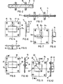
- the mentioned plates may be of the type marked 14, having holes 15 for coupling and fastening to the projections 63 of base 1, and holes 15a and 15b for fastening, on the upper side, to the profiles on which rest the various panels.
- the upper surface of plate 14 is provided with an elevation 16, comprised by a U-shaped profile with arms pointing upwards, and a further side elevation 17, comprised by a T-shaped profile with the stem pointing upwards.
- elevation 16 comprises an L -shaped plan view and an inverted T-shaped cross section.
- plate 19 of Figures 9 and 10 has holes 15 and holes 20 and the elevation 21 adopts an inverted U shape.
- Plate 19a of Figures 11 and 12 is likewise provided with holes 15 and 20, and an angular elevation 22 having a U-shaped cross section.
- All the mentioned plates 14, 14a, 19 and 19a are used to place the prefabricated columns thereon, either directly of through longitudinal profiles, such as those shown in Figures 2 and 3, which act as seating or support for the various panels 2, 4,and 5, both interior and exterior, and other interior columns such as those marked M in Figure 16.
- Figures 9 and 11 are provided with end holes 12 and 13, together with intermediate support elements having slit bores, not marked, through which said profiles are fastened to the different plates 14, 14a, 19, 19a, the plates and profiles making up a perfectly level web on which are arranged all the interior and exterior columns and wall panels or modules of the building.
- plates 14, 14a, 19 and 19a as shown cover all possible solutions for support of columns and panels, and they may therefore be suitably combined to meet all possible solutions.
- plate 14 may hold a column on its elevation 16, a panel on elevation 17 and profiles 9 at the ends of 16, which would be fastened at 15a.
- Plate 14a for example, may receive two profiles 11, fastened to 15b, and a centre column.
- Plate 19 may receive either a continuous profile 9 or 11 or profiles 9 and 11 at each end thereof, and a column in the middle.
- Plate 19a may receive a central column and respective side profiles.
- the interior and/or exterior wall panels are shown in Figures 13, l4,and 15.
- Said panels are made of a mixture of reinforced and prefabricated concrete, with an inner cavity duly filled with a suitable insulating material. Such is the case of wall panels 2, door panel 4 and window panel 5. All of said panels have at least one longitudinal groove 27 along their edges, for housing neoprene joints placed between each panel and its adjacent elements in order to achieve a suitable coupling and, more important, to obtain perfect airtightness.
- each panel has frontal bores 25 and 26, at least on one of the surfaces, together with further bores or ducts which penetrate thereinto from the edges, in correspondence with the middle plane thereof, to cross the previously mentioned bores.
- These latter bores are not marked in Figures 13, 14 and 15, but can be seen clearly in Figures 18, 21, 22, 24, 25, 26,and 27.
- Each pair of complementary bores cross each other within the panel, as shown in the mentioned Figures.
- the columns shown in their different versions in Figures 38 to 58, are likewise prefabricated and have lateral grooves 82, 86, 68a, etc., specially on the surfaces to be coupled to any one of the plates mentioned hereinbefore, such as, for example, those marked 4.
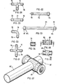
- fastening elements are embedded in the mass of reinforced concrete of the columns, which elements are comprised by rods such as those shown in Figures 28 to 31 and marked 71, 76, 77, and 71', being either straight, bent at 90 °, T-shaped or cross-shaped, and in all cases having threaded ends 78, said fastening elements being placed in the columns at the same height as bores 25 and 26 provided in the various wall panels, such as, for instance, those marked 2.
- the columns further include nuts 72 within the concrete mass and in correspondence with each of the threaded ends of elements 71, 76, 77, and 71', mentioned above, to engage the ends of said elements, with the particularity that said nut 72 is twice the length of the threaded end 78 of the elements, the outer mouth of the nuts 72 being thus completely on a level with the surface of the side wall of the column wherein they are embedded.
- the columns are reinforced and may include a middle longitudinal cavity filled with an insulating material 73 for preventing possible thermal conduction between the outside and the inside of the building. This characteristic can be seen clearly in Figures 24, 25 and 26, for example.
- Each column further has a series of longitudinal grooves on the sides and at the ends thereof, as shown in Figures 38 to 58.
- the purpose of the longitudinal grooves, marked 84 and 85 in Figures 24, 25, 26,and 27, for instance, is to house joints 50 and 50a, which act together with those of the wall panels or modules. Said grooves have not been marked on the various sections of Figures 41, 42, 46, 50, 54,and 56, in order to keep the drawing simple.
- FIG. 1 Other frontal grooves provided on the ends of the columns, such as those marked 83, 86, 87, and 88, are made such that the elevations of the alignment base plates may fit thereinto. See Figures 20 and 56, for instance, which show how the U-shaped elevation 21 fits into the grooves 88 of the ends of a panel or column.
- the grooves 87 in Figure 48 house the elevation 18 of plate 14a, shown in Figures 6 and 7.
- Grooves 89 of Figure 52 house the elevation 16-17 of plate 14, shown in Figures 4, 5, and 6, etc.
- each column is supported on the elevation of one of the plates of Figures 4, 7, 9, and 11, and that grooves are provided on the corresponding surface of the column for housing the upper edges of the elevation through insulating joints.
- the panels are shown diagramatically in Figures 13 to 15 and are marked 2, 3, and 4. They are made of reinforced concrete, the inner cavity being filled with insulating material 28.
- the edges of the panels are provided with a groove for coupling thereof to the elevations of the plates, to the profiles which rest on said plates, to adjacent panels, to columns, roof panels and possibly to the lower projections of plates constituting an upper web in modular buildings of more than one floor.
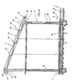
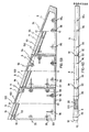
- Figures 16 and 17 show two views of a specific application of the invention.
- a panel 5 carrying a window 6 rests, for example, on profile 9, and is joined to a roof panel 7 along its upper edge by means of element 44.
- An inner panel (M) is likewise shown, and rests, for instance, on a profile 11 and on roof panel 7, at the ridge area 35-36-37.
- Panel 2 is likewise seated on profile 9.
- the panels are provided with bores 25-26, which are perpendicular thereto and placed near the edges, forming transversal ducts which penetrate into the panel.
- Said ducts are placed at predetermined positions in correspondence with elements 71, 71', 76,and 77 of columns 68, 74, 75, etc., and may either be through ducts, i.e., open on both sides of the panel, or open only on one side thereof.
- transversal bores there are provided further bores marked 69 and shown clearly in Figures 18, 21, 22, and 24 to 27, perpendicular to the former and on the same plane as the panel, which open towards the edge of said panel and cross and surpass the mentioned transversal ducts.
- Figures 21 and 22 which show the lateral coupling of exterior and interior panels, respectively, shall be referred to in the first place.
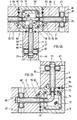
- Figure 21 shows two adjacent exterior panels 2 and 2' and the bores 25 and 26 leading to the transversal ducts 47. Ducts 69 from the edge of the panel, which cross and pass ducts 47, can likewise be seen.
- the opposed edges of the two panels 2 and 2' and the corresponding longitudinal grooves 84, 85 and 90, grooves 84 and 85 housing joints 50 and 50a and groove 90 housing the expanded material 66 which aids thermal breakdown between the outside and the inside of the prefabricated building, are likewise shown.
- the interior panels of the building shown at Figure 22 obviously do not require the provision of expanded material, and may furthermore be of lesser thickness than the exterior panels, given that the insulating coefficient required therefor is also less, but the internal ducts are the same.
- Figures 24, 25,and 26 show the coupling between panels and columns, together with the detail of Figure 27 which shows duct 47 closed to the outer surface of panel 2.
- FIGS. 25 and 26 show transverse sections of the coupling between a column and three panels, between two corner panels and between two coplanar panels.
- a column 68 ( Figure 24), the T-shaped element 71 and nuts 72 thereof being embedded therein, is coupled to each panel 2 with the aid of joints 50 and 50a, housed between each panel and the column 68, in addition to grooves 86, provided in both elements for housing the expanded material 73.
- Elements 71 extend straight towards ducts 69, which duct is crossed by the transversal bore 47. The same occurs in the couplings shown in Figures 25 and 26, no further explanations being necessary.
- Figure 23 showing two roof panels 7, shows how said panels form a lower projection or heel 44
- Figure 18 shows the coupling between a panel 2 and said heel 44, wherein the heel 44 is likewise provided with grooves 67 in correspondence with those provided in panel 2 for housing joints 50, the bores 47 and 69 being likewise shown in both panels.
- a panel 2 which rests on the lower plates and profiles mentioned hereinbefore, is coupled to other panels, to the columns and to the roof panel 7 through its upper edge with the aid of all the grooves, joints, expanded material and ducts crossing each other in the panels and in heel 44 of roof panels 7.
- FIGS 18, 21,and 22 show the device 45, shown in detail in Figure 32, the double- thread nut 49, shown in detail in Figures 35 and 36, and screws 48 as essential elements.
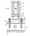
- the device 45 comprises a steel bolt or rod, the heads 46 and 46' whereof expand into frusto-conical sectors 46a and 46'a, which bolt is designed to penetrate into the bores 69 until the ends 46 pass the transversal bore of nut 49.
- screws 48 have frusto-conical ends, such that after assembling the device and tightening the screws, the internal frusto-conical ends of said screws abut the frusto-conical sectors 46a and 46'a of heads 46 and 46' established at the ends of bolt 45, the panels 2 are compressed against each other, holding joints 50 therebetween, as in panels 65 of Figure 22, whilst in the case of Figure 18, the weight of the roof serves this same purpose.
- a different embodiment is foreseen for the bolt or fastening device, shown at Figure 32, and marked 70, said bolt having a single expanded head 711, similar to one of the heads 46' of bolt 45, whereas the other end comprises a threaded sector 79 designed to engage column nut 72 on fastening a panel to said column.
- the fastening devices or bolts 45 and 70 may be standardised to give a single unit for general use. Thus, there may be manufactured only bolts like the one marked 70, and these used indifferently for fastening a panel to a column or for coupling two panels together, two bolts 70, joined by their threaded ends 79 with the aid of a nut similar, for example, to nut 72 used for fastening the bolt 70 to one of the elements or rods 71, 71', 76,or 77 embedded in the column, being used to make up fastening unit 45.
- the nut 72 is shown in Figure 34, and nut 49 with duct 80 for housing bolt 45 or 70 is in turn shown in Figures 35 and 36.
- the roof panels 7 appear specifically in Figure 23, which shows two roof panels fastened to each other, and in Figures 16 to 19.
- Each roof panel is comprised by a middle, stepped portion 29, the steppings having rounded edges, and two end flanges 8a in correspondence with their longitudinal edges.
- the lower surface of portion 29 is provided with a heel 44, mentioned hereinbefore, for coupling to the upper edge of an exterior wall panel, and the sides of flanges 8a are provided with grooves 67 for housing joints 50 which, on fastening, render the coupling between roof panels airtight.
- Figure 18 shows the provision of one of the transversal bores, provided in walls 41 of each panel 7, which house through-screws and nuts 40 for lateral fastening. Similar bores can be seen in Figure 19, which shows the ridge area 36 of roof panels 7, the elevations or steppings 35 and 37 thereof being likewise transversally bored and joined by bolt 52a-54 and nut 55 through an intermediate resilient element 56, all of which is duly covered by peak 53, wings 53aof said peak resting on the middle sectors 29 established between flanges 8a of each module.
- Said peak is continuous and may be combined with covers, not shown, for every two flanges 8a, for example, of the ridge parts.
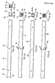
- Figures 59 and 60 show an elevation and upper plan view, respectively, of the gables.
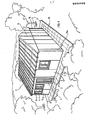
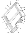
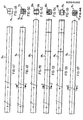
- Said gables are comprised by a series of modules 8, as shown in Figure 1, Figures 59 and 60 showing the three modules which, in the preferred embodiment of the invention, make up the gable for one of the slopes of the roof, it being obvious that the number of modules used will depend on the size of the building.
- each of the modules 8 making up the gable is shown in accordance with a central cross- section along lines IV-IV, V-Vand VI-VI, such that the inner surface of the module, showing grooves 100 for airtight coupling to the roof modules, appears to the left of the lines, and a cross section of the modules along their central plane appears to the right.
- the outer surface is smooth and the side edges are provided with grooves 91-92 for housing the joints between each gable and the next.
- Grooves 91 and 92 shown to the left of Figure 60 establish the airtightness, with the aid of respective neoprene joints, in relation to the central column M.
- Each gable module 8 has an inner cavity filled with thermo-insulating material 28, the resulting thickness of the wall 101 on either side thereof being minimal.
- the gable modules are coupled to roof panels 7 through the previously mentioned grooves 100 provided on the inner surface of each gable module, specifically through the joints established therein.
- the gable modules 8 are provided with interior projections 97-98, by means of which they are laterally fastened to each other, inner projection 95 for fastening to the central column M, and inner projections 96 on their lower edge for fastening to the exterior wall panels of the building. All of said projections 95-96-97-98 have a structure, based on crossed bores, which is identical to that of the panels and column, coupling of the gable modules to the panels and to the central column being therefore the same as that described for wall panels to columns and roof panels.
- the corner columns are provided with an upper bore which extends from the upper surface to a horizontal through bore which, in a manner identical to that of the panels, allows coupling between gable and column.
- All of panels 2, 4, 5 have transversal bores 47, either blind or not, bores 69 on the side edge and bores 69 on the upper end, as shown, for example, in Figure 18.
- a standard panel has four through bores 25-26, thereby establishing the bores on the side edges for receiving the columns and other panels.
- Two further bores, not marked in Figure 15, are additionally provided, said bores likewise being either through-bores or blind bores and communicating with another two bores which penetrate thereto from the upper edge of panel 2. All of such bores allow coupling of the wall panels to heels 44 of roof panels 7 and to the gable modules 8, shown in Figures 1, 59, and 60.
- a standard panel has four bores 25-26, as mentioned above, at a distance of 1 metre from each other and 30 cm from the upper and lower edges, in a panel of height 2.60 metres. Two unmarked bores are additionally provided, the distance between them being 1 metre, and each being 30 cm from the corners of the panel.
- FIGS 1, 17,and 19 show the central column M, which crosses the suspended roof 30-31 of the modular building to attain the ridge area 35-37.
- the suspended roofs 30-31 are arranged in a conventional manner, hanging from the upper roof panels 7 to form an upper chamber in the position of joists 38. This upper chamber is studied, though not claimed, by the invention in the manner to be hereinafter described.
- the central column or columns M may be comprised either by a single unit which crosses the suspended roof to attain the ridge, or by two separate units placed one on top of the other and joined, for example, through upper and lower plates and projections.
- Figure 19 there is provided a column M which is coupled to a T-shaped profile 58, the stem whereof points downwards, through its upper edge, the profile 58 receiving joints 57 which are coupled to joists 38 under the meeting point or aperture of the ridge, at exactly the place whereat joint 56 is located.
- the interior columns and panels 65 rest prefer/ably on plate elevations and profiles having a T-shaped section 11, with the stem pointing upwards, as airtightness is ensured with a single joint by reason of the panels being inside the building (see Figures 16 and 17).
- the panels may be of the same or of different thicknesses.
- the use of identical panels results in a perfectly modular building.
- the use of thinner interior panels as compared to the exterior panels would result in a substantial reduction in the cost of the building.
- the panels may have a blind surface (see Figure 27), i.e., duct 47 may not penetrate to the exterior surface thereof.
- outer closing elements When this is not so, i.e. when duct 47 is a through- duct, outer closing elements must be provided, which elements are not shown by reason of the fact that any suitable device currently on the market may be used.
- a further advantage of the invention which can be inferred from the structure described is that water pipes, tubes for electrical wiring and TV cables, etc., may be set up in the cavities of the panels, using, for instance, the actual ducts established between the panels. These auxiliary ducts may leave the panels at desired positions.
- One of the purposes of said joint 50a is to protect the inner joint 50, and another is to allow a certain amount of ventilation to preserve said joint and to facilitate ventilation.
- a final characteristic of the invention relates to the ventilation of the building, i.e., to the air ducts and passages which allow the building to be lived in.
- Special joints 50a between the panels, as mentioned before, are provided, at least partially, for this purpose.
- the air from the floor of the modular construction in Figure 1 naturally rises towards the roof, which must be internally provided with suitable ventilation means.
- Figure 19 shows a central separationabetween the ends of ridges 35 and 37.
- Figure 23 further shows a spacing between wing 39 of roof panel 7 and heel 44, to which is coupled a wall panel 2, 4,or 6.
- Heel 44 is provided with an unmarked bore, which crosses same, thereby establishing a passage through which air entering from the outside may reach the upper chamber. Once in said chamber, the air passes through the mentioned spacings, is evacuated up and out through the spacings established between the joints 57 provided on joists 38 of Figure 17, and from there to the outside, under part 53 shown in Figure 19.
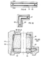
- a band element 103 of reinforced concrete is provided between the exterior walls of the building, comprised by panels 2, 4 and 5, and the roof thereof, comprised by modules 7, which band can be straight, as in Figure 61, or L-shaped 103' as in Figure 62, and has a shallow channel 104 of rectangular section on its lower side, the width of said channel being equal to that of the exterior wall modules 2, 4,and 5, the upper edge whereof fits into channel 104, as shown in detail in Figure 64, said channel 104 further including small grooves 105 which are complementary to those provided on the upper edge of the actual wall panels 2, 4,and 5 and are designed to house and deform the corresponding airtight joints 106 after coupling.
- the band 103 has, on its inner surface and as a further essential characteristic, a large stepping 107 which affects it mainly with respect to its height and which defines a ledge for the coupling, and specifically for supporting, the end areas of modules 108 which constitute a finishing element established in the building, at a level with roof 7.
- Each band module 103 additionally includes a further stepping 109 on its upper base, similar to the lower channel 104 but open internally, which is likewise provided with grooves 110, the stepping being designed to receive the heellll of roof modules 7, in such a way that the grooves 110 of the band are operatively opposed to those provided in the lower free edge of the heellll , allowing the coupling and deformation of joints 112, which are similar to those mentioned previously and marked 106.
- Coupling of the band modules 103 to the exterior wall modules 2, 4, 5 is effected simultaneously to the coupling of the roof modules 7, the latter including, on their lower edge, a preferrably inverted V-shaped metal profile 113 with a considerably narrowed mouth, as shown in detail in Figure 64, said profile being designed to house, with a possibility of longitudinal displacement, nut 114 which engages threaded end 115 of a screw or bolt 116 which crosses the band module 103 through bore 117 operatively made therein and penetrates into wall panel 2-4-5 through the vertical, coplanar bore 117 provided in said module in correspondence with each of the bores 117 provided in the band module, to cross the transversal bore 118 wherein is housed setscrew 119, having a frusto-conical front and which, on being actuated, affects the likewise frusto-conical sector 120 of the expanded head 121 of bolt 116, in a manner similar to that of the lateral coupling between wall panels, or between a panel and a column,
- finishing modules 108 these are comprised by a thin laminar body 108 provided with a short perimetral flange 122, being vertical and ascending, which stiffens the structure thereof, with the aid of intermediate and transversal walls 123, which are likewise shown in Figure 64, with the particularity that the perimetral flange 122 of said finishing modules is considerably higher than stepping 107 provided in the band modules, wherefore said finishing modules 108 work together with the band modules to inwardly close the stepping 109 provided in the latter and to form a channel similar to the one provided on the lower base thereof, marked 104, this being of greater importance in buildings having more than one floor, in which case the finishing modules aid the correct coupling of the exterior wall panels of the upper floor.
- the perimetral flange 122 of said finishing elements 108 are provided, preferrably between the two stiffening walls 123 with bores 124, for lateral coupling between said modules, with the aid of through-screws and respective nuts, the finishing elements being furthermore provided with end bores 125 for coupling to the band modules 103 with the aid of screws 126 and nuts 127, the latter being embedded in the band modules.
- roof panels 7 are practically identical in structure to the finishing modules 108, the only difference being the provision of the heel 111 through which the roof panels rest on, and are coupled and fastened to, exterior wall modules 2-4-5, with the insertion therebetween of band module 103.
- band module 103 includes a small groove 128, as shown in Figure 63, at the edge of the channel or stepping 109, wherein are coupled the heels 111 of roof modules 7, or the exterior walls of an upper floor, which groove acts as a collector for rainwater, water due to condensation, etc., and communicates with the front lower area of band module 103 through ducts 129 being suitably distributed along the band modules and which obviously drain said water to the outside of the exterior wall panels 2-4-5.
- Means for arranging finishing elements are thus available to the modular structure, specially through band modules 103, together with an ornamental finish which improves the aesthetic appearance of the building.
Landscapes
- Engineering & Computer Science (AREA)
- Architecture (AREA)
- Physics & Mathematics (AREA)
- Electromagnetism (AREA)
- Civil Engineering (AREA)
- Structural Engineering (AREA)
- Building Environments (AREA)
- Load-Bearing And Curtain Walls (AREA)
- Tents Or Canopies (AREA)
- Residential Or Office Buildings (AREA)
- Buildings Adapted To Withstand Abnormal External Influences (AREA)
Applications Claiming Priority (4)
| Application Number | Priority Date | Filing Date | Title |
|---|---|---|---|
| ES543952A ES8705073A1 (es) | 1985-06-05 | 1985-06-05 | Mejoras introducidas en la estructuracion modular de edificios prefabricados. |
| ES543952 | 1985-06-05 | ||
| ES555227A ES555227A0 (es) | 1986-05-22 | 1986-05-22 | Mejoras introducidas en la estructuracion modular de edificios prefabricados |
| ES555227 | 1986-05-22 |
Publications (1)
| Publication Number | Publication Date |
|---|---|
| EP0204580A1 true EP0204580A1 (de) | 1986-12-10 |
Family
ID=26156105
Family Applications (1)
| Application Number | Title | Priority Date | Filing Date |
|---|---|---|---|
| EP86304316A Withdrawn EP0204580A1 (de) | 1985-06-05 | 1986-06-05 | Modularstrukturen für vorgefertigte Gebäude |
Country Status (10)
| Country | Link |
|---|---|
| US (1) | US4741135A (de) |
| EP (1) | EP0204580A1 (de) |
| JP (1) | JPS6237437A (de) |
| CN (1) | CN86103853A (de) |
| BE (1) | BE904882A (de) |
| BR (1) | BR8602602A (de) |
| GR (1) | GR861436B (de) |
| IT (1) | IT1204379B (de) |
| NO (1) | NO862229L (de) |
| PT (1) | PT82709B (de) |
Families Citing this family (17)
| Publication number | Priority date | Publication date | Assignee | Title |
|---|---|---|---|---|
| EP0232842B1 (de) * | 1986-02-05 | 1992-05-06 | Siegmar Kohlenbrenner | Elementkonstruktion, insbesondere Wand- und/oder Deckenkonstruktion |
| NO882685L (no) * | 1988-06-17 | 1989-12-18 | Kirsten Birkeland | Innredningssystem. |
| US5471804A (en) * | 1988-11-21 | 1995-12-05 | Winter, Iv; Amos G. | Building system using prefabricated building panels and fastening components used therewith |
| US5472269A (en) * | 1992-12-07 | 1995-12-05 | Novikoff, Inc. | Modular furniture system |
| CN1061410C (zh) * | 1995-09-29 | 2001-01-31 | Git隧道建造有限公司 | 用于巷道衬砌的弓形件 |
| US6883281B1 (en) * | 1999-03-02 | 2005-04-26 | Hector E. Chavez-Gandara | Multiuse construction system: multispace 2000 |
| EP1090830B1 (de) * | 1999-10-05 | 2004-09-08 | Alcan Technology & Management AG | Baugruppenverbindung |
| US20060059823A1 (en) * | 2004-08-27 | 2006-03-23 | Wright Victor M | Wood cooking plank with easy to use split closure |
| CN105781125B (zh) * | 2016-03-04 | 2018-07-10 | 李藏柱 | 一种装配式建筑的安装方法 |
| CN108252432A (zh) * | 2018-01-25 | 2018-07-06 | 东莞市粤惠建筑工程技术咨询有限公司 | 一种模块化建筑系统 |
| FR3105277B1 (fr) * | 2019-12-24 | 2022-05-20 | Cochet Francois | Panneaux destinés à la fabrication d’un mur et procédés de fabrication de tels panneaux |
| CN111270614A (zh) * | 2020-02-18 | 2020-06-12 | 佛山新籁工程科技有限公司 | 一种用于桥梁柱体的模板 |
| CN111456432A (zh) * | 2020-03-16 | 2020-07-28 | 秦嘉慧 | 一种装配式水平拼接模板 |
| US12286990B2 (en) * | 2020-09-01 | 2025-04-29 | E. Leet Woodworking, Llc | Fastener system for furniture |
| US12667184B2 (en) * | 2020-09-01 | 2026-06-30 | Patrick John Leet | Fastener system for slatted construction |
| CN112459463B (zh) * | 2020-11-12 | 2022-06-17 | 上海宏构建筑科技发展有限公司 | 一种防刮痕易拼装的铝膜板 |
| ES1275081Y (es) * | 2021-04-22 | 2021-10-22 | Elastic Potential S L | Viga de hormigon y sistema que comprende a dicha viga |
Citations (7)
| Publication number | Priority date | Publication date | Assignee | Title |
|---|---|---|---|---|
| FR556097A (fr) * | 1922-09-15 | 1923-07-11 | Système de construction en panneaux armés | |
| FR863026A (fr) * | 1940-01-23 | 1941-03-21 | Construction démontables | |
| CH294270A (fr) * | 1950-11-16 | 1953-11-15 | J & E Puenzieux Freres | Bâtiment en éléments préfabriqués. |
| BE838768A (fr) * | 1976-02-20 | 1976-06-16 | Procede de montage d'immeuble a partir d'elements prefabriques et immeubles ainsi realises | |
| US4018021A (en) * | 1974-09-13 | 1977-04-19 | Jimmy Dow | Building and method of making same |
| OA06014A (fr) * | 1978-07-20 | 1981-06-30 | Rene Daement | Procédé de montage d'éléments préfabriqués utilisant des éléments de jonction standardisés. |
| US4299067A (en) * | 1979-10-30 | 1981-11-10 | J. C. Penney Company, Inc. | Partition connector system |
Family Cites Families (8)
| Publication number | Priority date | Publication date | Assignee | Title |
|---|---|---|---|---|
| US1397976A (en) * | 1917-11-14 | 1921-11-22 | Mcavoy Charles Frederick | Portable building or structure |
| US3017657A (en) * | 1959-08-19 | 1962-01-23 | Mills Prod Inc | Removable handle assembly for stove doors |
| SE329904B (de) * | 1968-02-09 | 1970-10-26 | Grafiset System Ab | |
| ZA721940B (en) * | 1972-02-22 | 1972-12-27 | Stabilator Ab | A locking joint for concrete piles comprising joined sections |
| GB1502869A (en) * | 1975-12-24 | 1978-03-08 | Iberica Del Frio Sa | Wall construction |
| US4012880A (en) * | 1976-04-28 | 1977-03-22 | American Store Equipment Corporation | Partition system |
| US4116573A (en) * | 1977-03-28 | 1978-09-26 | Fuchs Lothar U | Fastening |
| IT7722696U1 (it) * | 1977-11-10 | 1979-05-10 | Giovannetti F | Dispositivo per il fissaggio di parti in modo tra loro separabile. |
-
1986
- 1986-05-29 US US06/868,638 patent/US4741135A/en not_active Expired - Fee Related
- 1986-06-03 GR GR861436A patent/GR861436B/el unknown
- 1986-06-04 IT IT20674/86A patent/IT1204379B/it active
- 1986-06-04 BR BR8602602A patent/BR8602602A/pt unknown
- 1986-06-04 NO NO862229A patent/NO862229L/no unknown
- 1986-06-04 PT PT82709A patent/PT82709B/pt unknown
- 1986-06-05 JP JP61131652A patent/JPS6237437A/ja active Pending
- 1986-06-05 BE BE0/216751A patent/BE904882A/fr not_active IP Right Cessation
- 1986-06-05 EP EP86304316A patent/EP0204580A1/de not_active Withdrawn
- 1986-06-05 CN CN86103853A patent/CN86103853A/zh active Pending
Patent Citations (7)
| Publication number | Priority date | Publication date | Assignee | Title |
|---|---|---|---|---|
| FR556097A (fr) * | 1922-09-15 | 1923-07-11 | Système de construction en panneaux armés | |
| FR863026A (fr) * | 1940-01-23 | 1941-03-21 | Construction démontables | |
| CH294270A (fr) * | 1950-11-16 | 1953-11-15 | J & E Puenzieux Freres | Bâtiment en éléments préfabriqués. |
| US4018021A (en) * | 1974-09-13 | 1977-04-19 | Jimmy Dow | Building and method of making same |
| BE838768A (fr) * | 1976-02-20 | 1976-06-16 | Procede de montage d'immeuble a partir d'elements prefabriques et immeubles ainsi realises | |
| OA06014A (fr) * | 1978-07-20 | 1981-06-30 | Rene Daement | Procédé de montage d'éléments préfabriqués utilisant des éléments de jonction standardisés. |
| US4299067A (en) * | 1979-10-30 | 1981-11-10 | J. C. Penney Company, Inc. | Partition connector system |
Also Published As
| Publication number | Publication date |
|---|---|
| US4741135A (en) | 1988-05-03 |
| IT8620674A0 (it) | 1986-06-04 |
| JPS6237437A (ja) | 1987-02-18 |
| CN86103853A (zh) | 1987-02-04 |
| NO862229L (no) | 1986-12-08 |
| PT82709B (en) | 1989-03-03 |
| IT1204379B (it) | 1989-03-01 |
| BE904882A (fr) | 1986-10-01 |
| GR861436B (en) | 1986-10-02 |
| NO862229D0 (no) | 1986-06-04 |
| BR8602602A (pt) | 1987-02-03 |
| PT82709A (pt) | 1986-07-01 |
Similar Documents
| Publication | Publication Date | Title |
|---|---|---|
| US4741135A (en) | Modular structure for a prefabricated building | |
| US4674250A (en) | Modular building panel | |
| US4644708A (en) | Prefabricated modular building element and a building comprising such elements | |
| US5515659A (en) | Construction system using panelized insulation having integral structural frame | |
| US5371990A (en) | Element based foam and concrete modular wall construction and method and apparatus therefor | |
| US5353560A (en) | Building structure and method of use | |
| US4219978A (en) | Pre-cast reinforced concrete building panel wall structure | |
| US6141929A (en) | Insulated pre-formed wall panels | |
| US20070125042A1 (en) | Structural insulated panel construction for building structures | |
| US20090300999A1 (en) | New type of building, method and means for erecting it | |
| US4894964A (en) | Building structure and method | |
| US2139623A (en) | Precast hollow slab concrete construction system | |
| US20090120021A1 (en) | Modular structure | |
| US11479968B2 (en) | Mold design and process for constructing an insulated precast concrete wall system | |
| US4274242A (en) | Building systems | |
| KR20010012388A (ko) | 모듈라 샌드위치 패널과 주택건축방법 | |
| US20100083595A1 (en) | System for fabricating an aperture in a structure | |
| US20240167264A1 (en) | Modular, customizable, prefabricated building envelope system | |
| EP0623182A1 (de) | Verbesserte baustruktur und verfahren zur benutzung | |
| EP0427756B1 (de) | Bauelemente und deren verbindungen | |
| CA2274287C (en) | Concrete panel construction system | |
| WO1998048124A1 (en) | Building system and components of this system for modular do-it yourself houses | |
| US3665664A (en) | Building panel and structure constructed therewith | |
| EP0090473A1 (de) | Gebäude, Wandelemente und Profile für dieselben | |
| GB2166768A (en) | Prefabricated building elements with assembly joints |
Legal Events
| Date | Code | Title | Description |
|---|---|---|---|
| PUAI | Public reference made under article 153(3) epc to a published international application that has entered the european phase |
Free format text: ORIGINAL CODE: 0009012 |
|
| AK | Designated contracting states |
Kind code of ref document: A1 Designated state(s): AT DE FR GB NL SE |
|
| 17P | Request for examination filed |
Effective date: 19870519 |
|
| 17Q | First examination report despatched |
Effective date: 19890109 |
|
| STAA | Information on the status of an ep patent application or granted ep patent |
Free format text: STATUS: THE APPLICATION IS DEEMED TO BE WITHDRAWN |
|
| 18D | Application deemed to be withdrawn |
Effective date: 19900213 |