EP0205105B1 - Noyau pour la fabrication de roues à aubes centrifuges en élastomère - Google Patents
Noyau pour la fabrication de roues à aubes centrifuges en élastomère Download PDFInfo
- Publication number
- EP0205105B1 EP0205105B1 EP86107644A EP86107644A EP0205105B1 EP 0205105 B1 EP0205105 B1 EP 0205105B1 EP 86107644 A EP86107644 A EP 86107644A EP 86107644 A EP86107644 A EP 86107644A EP 0205105 B1 EP0205105 B1 EP 0205105B1
- Authority
- EP
- European Patent Office
- Prior art keywords
- core
- vane
- impeller
- core element
- passage
- Prior art date
- Legal status (The legal status is an assumption and is not a legal conclusion. Google has not performed a legal analysis and makes no representation as to the accuracy of the status listed.)
- Expired - Lifetime
Links
Images

Classifications
-
- B—PERFORMING OPERATIONS; TRANSPORTING
- B29—WORKING OF PLASTICS; WORKING OF SUBSTANCES IN A PLASTIC STATE IN GENERAL
- B29C—SHAPING OR JOINING OF PLASTICS; SHAPING OF MATERIAL IN A PLASTIC STATE, NOT OTHERWISE PROVIDED FOR; AFTER-TREATMENT OF THE SHAPED PRODUCTS, e.g. REPAIRING
- B29C45/00—Injection moulding, i.e. forcing the required volume of moulding material through a nozzle into a closed mould; Apparatus therefor
- B29C45/17—Component parts, details or accessories; Auxiliary operations
- B29C45/40—Removing or ejecting moulded articles
- B29C45/44—Removing or ejecting moulded articles for undercut articles
-
- B—PERFORMING OPERATIONS; TRANSPORTING
- B29—WORKING OF PLASTICS; WORKING OF SUBSTANCES IN A PLASTIC STATE IN GENERAL
- B29C—SHAPING OR JOINING OF PLASTICS; SHAPING OF MATERIAL IN A PLASTIC STATE, NOT OTHERWISE PROVIDED FOR; AFTER-TREATMENT OF THE SHAPED PRODUCTS, e.g. REPAIRING
- B29C33/00—Moulds or cores; Details thereof or accessories therefor
- B29C33/44—Moulds or cores; Details thereof or accessories therefor with means for, or specially constructed to facilitate, the removal of articles, e.g. of undercut articles
- B29C33/48—Moulds or cores; Details thereof or accessories therefor with means for, or specially constructed to facilitate, the removal of articles, e.g. of undercut articles with means for collapsing or disassembling
-
- F—MECHANICAL ENGINEERING; LIGHTING; HEATING; WEAPONS; BLASTING
- F04—POSITIVE - DISPLACEMENT MACHINES FOR LIQUIDS; PUMPS FOR LIQUIDS OR ELASTIC FLUIDS
- F04D—NON-POSITIVE-DISPLACEMENT PUMPS
- F04D29/00—Details, component parts, or accessories
- F04D29/18—Rotors
- F04D29/22—Rotors specially for centrifugal pumps
- F04D29/2205—Conventional flow pattern
- F04D29/2222—Construction and assembly
- F04D29/2227—Construction and assembly for special materials
-
- B—PERFORMING OPERATIONS; TRANSPORTING
- B29—WORKING OF PLASTICS; WORKING OF SUBSTANCES IN A PLASTIC STATE IN GENERAL
- B29L—INDEXING SCHEME ASSOCIATED WITH SUBCLASS B29C, RELATING TO PARTICULAR ARTICLES
- B29L2031/00—Other particular articles
- B29L2031/08—Blades for rotors, stators, fans, turbines or the like, e.g. screw propellers
- B29L2031/087—Propellers
-
- F—MECHANICAL ENGINEERING; LIGHTING; HEATING; WEAPONS; BLASTING
- F05—INDEXING SCHEMES RELATING TO ENGINES OR PUMPS IN VARIOUS SUBCLASSES OF CLASSES F01-F04
- F05D—INDEXING SCHEME FOR ASPECTS RELATING TO NON-POSITIVE-DISPLACEMENT MACHINES OR ENGINES, GAS-TURBINES OR JET-PROPULSION PLANTS
- F05D2230/00—Manufacture
- F05D2230/20—Manufacture essentially without removing material
-
- F—MECHANICAL ENGINEERING; LIGHTING; HEATING; WEAPONS; BLASTING
- F05—INDEXING SCHEMES RELATING TO ENGINES OR PUMPS IN VARIOUS SUBCLASSES OF CLASSES F01-F04
- F05D—INDEXING SCHEME FOR ASPECTS RELATING TO NON-POSITIVE-DISPLACEMENT MACHINES OR ENGINES, GAS-TURBINES OR JET-PROPULSION PLANTS
- F05D2300/00—Materials; Properties thereof
- F05D2300/40—Organic materials
- F05D2300/43—Synthetic polymers, e.g. plastics; Rubber
-
- Y—GENERAL TAGGING OF NEW TECHNOLOGICAL DEVELOPMENTS; GENERAL TAGGING OF CROSS-SECTIONAL TECHNOLOGIES SPANNING OVER SEVERAL SECTIONS OF THE IPC; TECHNICAL SUBJECTS COVERED BY FORMER USPC CROSS-REFERENCE ART COLLECTIONS [XRACs] AND DIGESTS
- Y10—TECHNICAL SUBJECTS COVERED BY FORMER USPC
- Y10S—TECHNICAL SUBJECTS COVERED BY FORMER USPC CROSS-REFERENCE ART COLLECTIONS [XRACs] AND DIGESTS
- Y10S425/00—Plastic article or earthenware shaping or treating: apparatus
- Y10S425/058—Undercut
-
- Y—GENERAL TAGGING OF NEW TECHNOLOGICAL DEVELOPMENTS; GENERAL TAGGING OF CROSS-SECTIONAL TECHNOLOGIES SPANNING OVER SEVERAL SECTIONS OF THE IPC; TECHNICAL SUBJECTS COVERED BY FORMER USPC CROSS-REFERENCE ART COLLECTIONS [XRACs] AND DIGESTS
- Y10—TECHNICAL SUBJECTS COVERED BY FORMER USPC
- Y10T—TECHNICAL SUBJECTS COVERED BY FORMER US CLASSIFICATION
- Y10T29/00—Metal working
- Y10T29/49—Method of mechanical manufacture
- Y10T29/49316—Impeller making
- Y10T29/4932—Turbomachine making
-
- Y—GENERAL TAGGING OF NEW TECHNOLOGICAL DEVELOPMENTS; GENERAL TAGGING OF CROSS-SECTIONAL TECHNOLOGIES SPANNING OVER SEVERAL SECTIONS OF THE IPC; TECHNICAL SUBJECTS COVERED BY FORMER USPC CROSS-REFERENCE ART COLLECTIONS [XRACs] AND DIGESTS
- Y10—TECHNICAL SUBJECTS COVERED BY FORMER USPC
- Y10T—TECHNICAL SUBJECTS COVERED BY FORMER US CLASSIFICATION
- Y10T29/00—Metal working
- Y10T29/49—Method of mechanical manufacture
- Y10T29/49316—Impeller making
- Y10T29/4932—Turbomachine making
- Y10T29/49323—Assembling fluid flow directing devices, e.g., stators, diaphragms, nozzles
Definitions
- the invention relates to a vane core assembly used in the molding of a shrouded impeller, of the kind described in the pre-characterizing part of the annexed claim 1.
- Shrouded impellers in which the vanes and vane passages are enclosed between a pair of opposed shrouds or disks are relatively commonplace in centrifugal pumps.
- Shrouded impellers are available in both metal and elastomer-covered metal constructions.
- Metal impellers are typically utilized in non-abrasive, non-corrosive environments.
- Elastomer-covered impellers because of expense and difficulty in making same, are typically utilized only where abrasive or corrosive resistance is required, for example, in slurry pumps handling abrasive or gritty solids in a liquid media or in dealing with corrosive liquids such as acids and the like.
- An elastomeric-covered impeller is formed about a metal insert.
- the technique involves placing the metal insert within a mold and providing core elements which provide for the voids within the impeller after molding. Elastomeric material is forced generally under pressure into the molds so that those spaces which exist between the metal insert and the core elements are filled with rubber thereby forming the elastomeric-covered shrouded impeller.
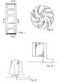
- FIG. 1 A typical rubber-covered impeller is shown in Fig. 1 in an elevational view showing the peripheral edge of the impeller with vane passage openings shown at the periphery.
- the formation of the throat opening and vane passages in the molding process is relatively straight-forward in this type of construction.
- FIG. 2 An elevational view of the vanes of a shrouded impeller along section lines 2-2 of Fig. 1 is illustrated in Fig. 2.
- the spacing between adjacent vanes is closer near the center of the impeller than around the outer edges of the vanes.
- the rotation of the impeller is counter-clockwise.
- the vane core which is a portion of the mold which forms the vane passage, has a uniform width "w" between the inner walls of the front and rear shroud.
- the front shroud is the shroud containing the inlet opening in the throat of the impeller.
- FIG. 4 shows some curvature of the inner walls of the front and rear shrouds. This wall curvature is to provide a flow channel from the inlet throat of the impeller into the vane passage which provides a gradual change of direction to accomplish the 90° change of direction from axial inlet flow to radial outlet flow.
- the vane passage of the impeller of Fig. 4 is formed by a pair of vane core members, A and B, whereby the width W A and width W B of each core member is smaller than the width "b" of the peripheral vane passage width. Extraction of these core members is perpendicular to the central axis of the impeller and is in the order of core A being first removed and then core B being later removed.
- metal impellers with enclosed vanes the formation of shrouds with curved inner walls has been practiced for quite some time.
- Metal impellers are generally formed by sand casting, whereby the formation of curved interior walls of the forwards and rear shrouds has been easily achieved since solid core members are not used in the casting process.
- the achievement of a channel connecting the inlet throat with the vane passage in a manner such that the channel encounters no sharp angle restrictions has been long practiced with metal impellers.
- a right-angle corner such as that present in the construction illustrated in Fig. 3, may cause velocity loss as well as turbulence near the square corner and cause erosion of the elastomeric covering on the back shroud in the area directly opposite to the square corner on the front shroud.
- US-A-3 189 681 describes a closed shrouded rubber lined impeller having a rubber lining which is molded on a metal skeleton by using a center core plug which is located in the inlet throat of the impeller skeleton and a couple of core elements which are axially superimposed to each other within the passage between each pair of adjacent skeleton vanes.
- each vane passage has an inlet central opening and an outlet peripheral opening having axial widths (i.e., width along the axial direction of the impeller) which are substantially identical to each other. Therefore, during the impeller operation, there is a substantial risk of undesirable flow patterns (e.g. vortices) due to the absence of guiding surfaces which can smoothly and continuously guide the flow during the 90° turn from the axial direction at the inlet to the radial direction of the outlet.
- undesirable flow patterns e.g. vortices
- each of the two superimposed core elements used at each vane passage in US-A-3 189 671 extends through the whole radial length (i.e. the length along the radial direction of the impeller) of the vane passage.
- the axial width of the passage inlet could be rendered at maximum twice the axial width of the outlet, which prevents the designer from shaping the surface of the vane passage so as to guide smoothly the flow during the 90° turn from the axial direction to the radial direction.
- the present invention provides a vane core assembly as described in the characterizing part of claim 1.
- the vane passage is a very irregular void having an axial width near the center of the impeller which is much greater than the axial width near the periphery of the shrouds, while the circumferential spacing between adjacent vanes is exactly the opposite with the greater distance between adjacent vanes occurring at the periphery of the shrouds and a narrow spacing between adjacent vanes occurring near the center of the impeller.
- the vane core elements are structured to be removed along an extraction surface between adjacent cores perpendicular to and away from the central axis of the impeller.
- the core elements are flat members which are curved along opposed edges to conform (and to form) the curved vanes.
- the curvatures along opposed surfaces of adjacent vanes which form a vane passage are mating surfaces so that the vane core members, as illustrated hereinafter, may be removed along an extraction path, as viewed from the face of the impeller, which is an arc.
- two of the vane core elements extend substantially the whole distance from the periphery of the vane passage to the inlet portion of the vane passage.
- the third vane core element does not extend the full radial distance of the vane passage.
- the instant invention involves a unique construction of the core used in the casting process of shrouded, elastomeric-covered impellers.
- Such impellers come in particularly small sizes, for example, less than about 30.5 centimeters in diameter, and are provided with a channel comprising the inlet throat and the vane passage which is essentially curvalinear. Fluid entering the pump enters axially through an opening in the front shroud and, through the centrifugal action of the pump, parts in a direction perpendicular to the original axial flow.
- the change of direction for fluids in the instant impellers is very gradual and distinctly different from that in existing elastomeric-covered, enclosed impellers.
- the curvature of the flow channel formed by the throat (inlet opening) through the vane passage to the peripheral exit for the impeller would ideally be a 90° arc of a circle.
- Such a construction would, of course, involve an impeller axial depth which was greater than about one-half the impeller diameter. While casting of metal impellers approximating such a construction in sacrificial molds is relatively straight-forward, molding complexities are encountered in making a comparable elastomeric-covered shrouded impeller.
- a mold assembly involving a central core member and a vane core mold assembly of at least three elements is utilized to approximate an ideal flow channel from inlet to discharge for an elastomeric-covered shrouded impeller for a centrifugal pump.
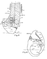
- FIG. 5 The unique channel arrangement associated with the instant invention is illustrated in FIG. 5.
- the throat inlet 10 connects to the vane passage, which in FIG. 5 is occupied by vane core mold members used in molding the appropriately shaped vane passage.
- FIG. 5 a very gradual change of direction occurs between fluid entering the throat and then changing directions at 90° to exit the vane core passage at the peripheral edge of the impeller.
- the vane core passage 11 is formed between the front shroud interior wall 12 and the interior wall 13 of the rear shroud.
- the curved surface of the rear shroud 13 continues below the vane core passage 11 to form a cone-shaped projection 14 with its apex at the central axis of the impeller 15.
- a steel impeller skeleton is first placed in the mold before rubber is injected.
- the steel skeleton shroud members 16 and 17, respectively, form the front and rear shroud inserts about which the elastomer forms to form the elastomeric-covered impeller shrouds.
- the interior wall of the front shroud adjacent to the throat inlet has a curvature as established by radius R.
- Radius R is generally determined by the diameter of the impeller and the amount of sweep desired. Furthermore, the curvature of the interior wall of the front shroud may be described by several different radii having different focal points.
- the juncture of the inner wall 12 of the front shroud with the throat inlet wall 18 approximates a curvalinear relationship, that is, the curvature of the inner shroud wall 12 is such that the throat inlet wall 18 is substantially tangential to the curved wall 12 at the point of juncture.
- the interior wall 13 of the rear shroud has a curvature such that at the apex of the cone 14 the curvature of the cone wall is such that an extension of such curved wall joins with the central axis 15 of the impeller in a curvalinear fashion, that is, the axis is substantially tangential to the extended curve of the curved wall of cone 14.
- the center core plug 19 is substantially cylindrical in shape at the throat inlet area and has longitudinal grooves circumferentially spaced equidistantly about the plug near the distal end. These grooves accommodate the formation of extensions of the vanes into the inlet throat and are dished on the end to form the conical projection 14.
- the center core plug mates with vane core elements A, B and C at boundary or parting surface 20. Vane core member A joins at parting line 21 with vane core member B. Parting line 21 is, in fact, a planar surface as illustrated in other drawings, and is substantially perpendicular to the central axis 15. Vane core member A has a maximum width W A , which must not be greater than its width at the exit of the vane passage.
- the width of W A must, of course, be less than the width of the exit as illustrated by letter "b". Preferably, the width W A is significantly less than the exit width "b".
- the second vane core member B should have a sufficient thickness near its exit to be sufficiently durable that it is not easily broken. For example, if core member A were substantially as thick as exit width "b" then core member B may be substantially a knife edge at its upper portions and, therefore, would be easily broken.
- the width of W which is the combined widths of core members A, B and C, is greater than the exit width "b".
- the width W B is not the maximum width of the element; however, the maximum width of core member B, which is near shoulder X, must be smaller than the exit width "b".
- Core members B and C are formed with a shoulder X so that again a sliver or knife edge is not required on core member C. Structuring core member C such that it is recessed slightly into core member B makes core member C an easier part to fabricate and assures a better seal at the sealing surfaces between core members so that the mold surface presented to form interior wall 12 is a continuous surface.
- Core member C and core member B are joined together by pins projecting from core member C which are recessed within bores in core member B. Conversely, the pins could be affixed to core member B and the bores recessed within core member C.
- a pry slot 26 is provided for insertion of a screwdriver or the like to pry the cores B and C apart.
- air injection port 27 is provided in core member B so that air pressure may be introduced into bores 24 and 25 to eject pins 22 and 23 to separate cores C and B.
- Pry slot 26 and air injection port 27 are at a boundary surface between cores B and C and the center core plug so that the elastomer in liquid form, as it is filling the mold, cannot reach the slot 26 or port 27, so that these remain open and unfilled with rubber.
- FIG. 6 A frontal or elevational view of core member C is illustrated in FIG. 6.
- Core C has a substantially crescent shape; the central circle 28 illustrates the cylindrical wall of throat 10.
- FIG. 6 illustrates the central core plug 19 positioned in place with grooves 29 in the distal cylindrical surface of the plug spaced so as to form the interior tips of the vanes which protrude into the throat region.
- core member C at surface 30 forms a portion of the surface of a vane 31 while the surface 32 of the core C forms a surface of a vane 33.
- the juncture line X is illustrated showing a juncture surface between core B and core C.
- Surface 34 is the parting surface formed between core C and the central core plug 19.
- Pry slot 26 is shown in dotted lines as is injection port 27 which interconnects bores 24 and 25.
- FIGS. 7, 8, 9 and 10 illustrate sequentially the removal of vane core members A, B and C and central core plug 19.
- FIG. 7 is a perspective view of an elastomeric-covered impeller which has been molded and which has had the center core plug 19 removed. Also, three quadrants of the vane passage core sub-assemblies have been removed. In molding a complete impeller with four vanes and four vane passages, four vane core sub-assemblies similar to the sub-assembly shown in FIGS. 7 through 10 are utilized so that four vanes are formed and four vane core passages are formed in the impeller. In FIG. 7, cores A, B and C are still positioned within the impeller.
- vane core A has been removed.
- Core A has a rim 34 which is substantially as thick at its outer edge as the vane passage of the impeller.
- a quarter-circle, arc-like shoulder 35 is formed in the rim 34, said shoulder having a thickness substantially the same as the thickness of the rim 36 of vane core B.
- vane core B is shown after it has been removed from the impeller.
- Vane core B has an outer rim 36 which is a quarter of a circle in its arc and mates with the quarter-circle shoulder 35 of vane core A.
- Vane core B has a tongue 38 which extends into the vane core passage.
- the edge surfaces of tongues 37 and 38 are illustrated in FIG. 5 and the tongues have a width, W A and W B , as indicated in FIG. 5.
- FIG. 10 shows vane core C removed from the impeller.
- the substantially crescent-shaped vane core C is illustrated.
- FIGS. 7 through 10 similar vane core elements could be utilized to form any number of vane passages and vanes in an enclosed shrouded impeller.
- an impeller could be formed having three, five, six, or any number of vanes and vane passages in which the rim portions of the cores A and B, respectively, would be one-third, one-fifth and one-sixth of a complete circle.
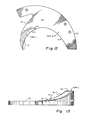
- FIG. 12 A facial view of core elements B and C is presented in FIG. 12.
- Cores A and B have substantially the same overall shape; i.e., core B may set in with core A.
- the flat planar surfaces of core A are parallel to one another while core B has one flat planar surface which mates with a flat planar surface of core A.
- the other facial surface is a curved surface such that the width between opposed faces of the tongue increases with distance from the rim.
- the sweep of surface is such that it continues with the surface of core C.
- That edge of core C designated by the numeral 40 is that portion which mates with the center cylindrical plug of the mold.
- Edge 41 of the tongue of core B forms one surface of a vane while edge 42 forms a surface of an adjacent vane.
- the space occupied by the tongues of cores B and C between adjacent vanes is a vane passage.
- the view in FIG. 13 is an edge-on rim view of cores B and C illustrated in FIG. 12.
- the outer edge 43 of the rim has a certain width, which is the width also of the tongue member adjacent the rim.
- the tongue of core B increases in thickness with distance from the rim, as illustrated in FIG. 13.
- the joint 44 between core C and core B is at the shoulder joint between these two elements.
- the offset of the shoulder is about the same as the increase in thickness of the tongue of core B from the rim to the shoulder.
- surfaces 40 and 45 are part of core C.
- the depth of the shoulder 44 and thickness of core B may be viewed in FIG. 5.
- the thickness of edge 40 at its junction with shoulder 44 is about the same as the thickness of edge 41 at its juncture with shoulder 44.
- the mating surfaces between cores C and B are flat planar surfaces which have a substantially cresent-shaped outline.
- FIG. 11 an edge-on elevational view of an impeller of the invention is illustrated.
- the center of gravity of the impeller is shifted towards the inlet opening.
- a consequence of the increased width of the impeller and the shift in the center of gravity is to position the center of gravity farther from the external bearing supporting the impeller shaft.
- a larger shaft and bearing are generally required.
- Elastomeric impellers of the type of the instant invention for an impeller of a given diameter will generally weigh more than conventional elastomeric prior art impellers, assuming the same thickness of elastomeric covering. Such increase in weight further would require an increase in shaft and bearing size.
- increased shaft and hearing sizes required for construction of this type may have lead those skilled in the art away from making impellers of the type of this invention.
- the elastomeric-covered impellers of this invention provide a significant increase in hydraulic efficiency, a significant decrease in power consumption, and improved impeller life when compared with prior art-type impellers of similar diameters.
- a smaller diametered impeller of the instant invention may be effectively substituted for larger diametered impellers of the prior art type, so that no real increase in shaft size or bearing size actually occurs when determined by pump performance.
- Molding of elastomeric-covered impellers is done under very high pressure; i.e., injection pressures of 10.3 MPa (1500 psi) to about 13.8 MPa (2000 psi) with internal mold pressure spikes of upwards of 34.5 MPa (5000 psi) to about 41.4 MPa (6000 psi).
- high pressures require mold elements which are particularly rugged, especially for vane core elements which, in the instant invention, are cantilevered from an external rim member.
- Elastomeric-covered impellers of this invention have pumping efficiencies which are significantly improved over previous configurations of elastomeric-covered impellers.
- small diameter impellers of from about 15 centimeters to 30.5 centimeters in diameter show improvements of about 30% in pump efficiency when compared to other similarly sized pumps with configurations such as those show in FIGS. 1 and 2.
- Another measurement of improvement for the pumps of the instant invention is that power requirements to pump a certain volumetric rate of liquid to a certain head is accomplished with signficantly less power consumption.
Landscapes
- Engineering & Computer Science (AREA)
- Mechanical Engineering (AREA)
- General Engineering & Computer Science (AREA)
- Manufacturing & Machinery (AREA)
- Structures Of Non-Positive Displacement Pumps (AREA)
- Moulds For Moulding Plastics Or The Like (AREA)
- Centrifugal Separators (AREA)
- Conveying And Assembling Of Building Elements In Situ (AREA)
- Geophysics And Detection Of Objects (AREA)
- Turbine Rotor Nozzle Sealing (AREA)
- Placing Or Removing Of Piles Or Sheet Piles, Or Accessories Thereof (AREA)
- Processing And Handling Of Plastics And Other Materials For Molding In General (AREA)
- Saccharide Compounds (AREA)
- Materials For Medical Uses (AREA)
- Micro-Organisms Or Cultivation Processes Thereof (AREA)
- External Artificial Organs (AREA)
- Molds, Cores, And Manufacturing Methods Thereof (AREA)
Claims (12)
- Assemblage de noyaux pour aubes à utiliser dans la réalisation d'un passage (11) d'aubes entre deux aubes adjacentes, dans une roue à aubes fermée, formée par injection et recouverte d'un élastomère ; ladite roue à aubes ayant une entrée (10) qui communique avec ledit passage (11) d'aubes ; ledit passage d'aubes ayant une ouverture centrale contiguë à ladite entrée de la roue à aubes, une ouverture périphérique contiguë à une périphérie de ladite roue à aubes et une première longueur définie comme étant une distance entre ladite ouverture centrale et ladite ouverture périphérique ; une longueur de ladite ouverture centrale étant sensiblement inférieure à une longueur de ladite ouverture périphérique ; ladite ouverture centrale étant transposée depuis un alignement d'axe central avec ladite ouverture périphérique ; ledit assemblage de noyaux pour aubes comportant :- un premier élément de noyau (A) pour aubes, ledit premier élément de noyau (A) étant dimensionné de façon à s'étendre sensiblement de ladite ouverture centrale jusqu'à ladite ouverture périphérique dudit passage d'aubes ;- un second élément de noyau (B), monté de façon amovible sur ledit premier élément de noyau (A) ; ledit second élément de noyau (B) étant dimensionné de façon à s'étendre sensiblement de ladite ouverture centrale jusqu'à ladite ouverture périphérique dudit passage d'aubes ;- un bouchon de noyau central (19) destiné à être placé dans l'entrée (10) de la roue à aubes ;caractérisé en ce que ledit assemblage de noyaux pour aubes comprend un troisième élément de noyau (c) placé sur le côté extérieur du bouchon de noyau central (19) et monté de façon manuellement détachable à l'aide de moyens de fixation sur ledit deuxième élément de noyau (B) ; ledit troisième élément de noyau (C) étant monté de façon à être en position adjacente à ladite ouverture centrale dudit passage d'aubes (11) ; ledit troisième élément de noyau (C) ayant une longueur inférieure à ladite première longueur, de manière que ledit troisième élément de noyau (C) puisse s'étendre de ladite ouverture centrale jusqu'à un emplacement situé à peu de distance de ladite ouverture périphérique ; lesdits moyens de fixation étant configurés de façon à être accessibles à partir de ladite entrée de la roue à aubes lorsque ledit assemblage de noyaux pour aubes se trouve dans ledit passage d'aubes (11), afin que ledit troisième élément de noyau (C) puisse être détaché manuellement dudit deuxième élément de noyau (B) par une manoeuvre desdits deuxième (B) et troisième (C) éléments de noyaux à travers ladite entrée (10) de la roue à aubes, la largeur de ladite ouverture centrale étant sensiblement plus grande que la largeur de ladite ouverture périphérique.
- Assemblage de noyaux pour aubes selon la revendication 1, caractérisé en ce que les moyens de fixation comprennent au moins une broche (22, 23) reçue de façon amovible dans deux alésages (24, 25) situés dans des positions opposées, définis, respectivement, dans lesdits troisième (C) et deuxième (B) éléments de noyaux.
- Assemblage de noyaux pour aubes selon la revendication 2, caractérisé en ce que ledit assemblage de noyaux pour aubes comprend une fente (26) pour levier, placée à proximité d'une surface limite entre lesdits troisième (C) et deuxième (B) éléments de noyaux, ladite fente étant dimensionnée de façon à recevoir un outil et à faciliter une séparation par effet de levier desdits troisième (C) et deuxième (B) éléments de noyaux.
- Assemblage de noyaux pour aubes selon la revendication 2, caractérisé en ce que ledit assemblage de noyaux pour aubes présente un orifice (27) d'injection d'air ; ledit orifice (27) étant destiné à recevoir de l'air comprimé provenant d'une zone proche de ladite entrée (10) de la roue à aubes et à diriger cet air contre ladite broche (22, 23) pour déloger ladite broche (22, 23) de son alésage (24, 25), afin que lesdits deuxième (B) et troisième (C) éléments de noyaux soient séparés à force.
- Assemblage de noyaux pour aubes selon la revendication 1, caractérisé en ce que lesdits premier et deuxième éléments (A, B) de noyaux pour aubes sont de forme incurvée définissant un passage (11) d'aubes en forme d'arc.
- Assemblage de noyaux pour aubes selon la revendication 5, caractérisé en ce que ledit premier élément de noyau (A) et ledit deuxième élément de noyau (B) présentent chacun une surface plane d'accouplement afin que lesdites surfaces respectives d'accouplement puissent être placés dans des positions contiguës entre elles pour permettre une action de glissement dudit premier élément de noyau (A) le long dudit deuxième élément de noyau (B).
- Assemblage de noyaux pour aubes selon la revendication 6, caractérisé en ce que ledit troisième élément de noyau (C) s'accouple de façon amovible avec une partie d'une surface (39) dudit deuxième élément de noyau (B), laquelle surface (39) est opposée à une surface (21) dudit deuxième élément de noyau (B) qui s'accouple de façon plane avec une surface correspondante dudit premier élément de noyau (A).
- Assemblage de noyaux pour aubes selon la revendication 7, caractérisé en ce que ledit assemblage est configuré pour être retiré, élément par élément, dudit passage (11) d'aubes sensiblement dans un plan perpendiculaire à un axe central (15) de ladite roue à aubes et suivant un trajet globalement analogue à un arc correspondant audit passage (11) d'aubes en forme d'arc.
- Assemblage de noyaux pour aubes selon la revendication 8, caractérisé en ce que lesdits premier (A) et deuxième (B) éléments de noyaux sont configurés pour permettre un dégagement par glissement l'un de l'autre, dans lequel ledit premier élément de noyau (A) peut être retiré initialement en glissant dudit passage (11) d'aubes et ledit deuxième élément de noyau (B) peut ensuite être retiré, ledit retrait dudit premier élément de noyau (A) établissant un espace suffisant à l'intérieur dudit passage (11) d'aubes pour permettre de séparer ledit deuxième élément de noyau (B) dudit troisième élément de noyau (C) avant de commencer à retirer ledit deuxième élément de noyau (B) dudit passage (11) d'aubes.
- Assemblage de noyaux pour aubes selon la revendication 1, caractérisé en ce que ledit premier élément de noyau (A) comporte un rebord extérieur (34) configuré de façon à coopérer avec un rebord extérieur (34) d'un second premier élément de noyau (A) pour retenir ainsi ledit premier élément de noyau (A) fixement vis-à-vis dudit second premier élément de noyau (A).
- Assemblage de noyaux pour aubes selon la revendication 1, caractérisé en ce que ledit deuxième élément de noyau (B) comporte un rebord extérieur (36) qui coopère avec le rebord (34) de son premier élément respectif de noyau (A) pour former une liaison manuellement détachable dudit premier élément de noyau (A) et dudit premier élément de noyau (B).
- Assemblage de noyaux pour aubes selon l'une quelconque des revendications précédentes, caractérisé en ce que la largeur de ladite ouverture centrale est au moins double de la largeur de ladite ouverture périphérique.
Priority Applications (1)
| Application Number | Priority Date | Filing Date | Title |
|---|---|---|---|
| AT86107644T ATE77449T1 (de) | 1985-06-10 | 1986-06-05 | Giesskern fuer die herstellung von zentrifugalschaufelraedern aus elastomer. |
Applications Claiming Priority (2)
| Application Number | Priority Date | Filing Date | Title |
|---|---|---|---|
| US06/743,067 US4706928A (en) | 1985-06-10 | 1985-06-10 | Vane cone assembly for use in making centrifugal elastomeric coated impellers |
| US743067 | 1985-06-10 |
Publications (2)
| Publication Number | Publication Date |
|---|---|
| EP0205105A1 EP0205105A1 (fr) | 1986-12-17 |
| EP0205105B1 true EP0205105B1 (fr) | 1992-06-17 |
Family
ID=24987392
Family Applications (1)
| Application Number | Title | Priority Date | Filing Date |
|---|---|---|---|
| EP86107644A Expired - Lifetime EP0205105B1 (fr) | 1985-06-10 | 1986-06-05 | Noyau pour la fabrication de roues à aubes centrifuges en élastomère |
Country Status (11)
| Country | Link |
|---|---|
| US (2) | US4706928A (fr) |
| EP (1) | EP0205105B1 (fr) |
| JP (1) | JPS61294196A (fr) |
| AT (1) | ATE77449T1 (fr) |
| AU (1) | AU595204B2 (fr) |
| BR (1) | BR8602678A (fr) |
| CA (1) | CA1270148A (fr) |
| DE (1) | DE3685689T2 (fr) |
| FI (1) | FI862378A7 (fr) |
| NO (1) | NO170817C (fr) |
| ZA (1) | ZA864325B (fr) |
Families Citing this family (26)
| Publication number | Priority date | Publication date | Assignee | Title |
|---|---|---|---|---|
| US4998706A (en) * | 1985-06-10 | 1991-03-12 | Baker International Corporation | Vane core assembly for use in making centrifugal elastomer coated impellers |
| US4923367A (en) * | 1988-03-14 | 1990-05-08 | Flint & Walling, Inc. | Submersible pump with plastic housing |
| DE3912031A1 (de) * | 1989-04-12 | 1990-10-25 | Thyssen Polymer Gmbh | Spritzgusswerkzeug |
| US4975041A (en) * | 1989-05-18 | 1990-12-04 | Fries Steven L | Die assembly for die casting a propeller structure |
| US5154574A (en) * | 1990-08-06 | 1992-10-13 | Ed Reinhorn | Gearless air motor |
| US5290236A (en) * | 1991-09-25 | 1994-03-01 | Baxter International Inc. | Low priming volume centrifugal blood pump |
| US5705204A (en) * | 1993-03-17 | 1998-01-06 | Mtu Motoren- Und Turbinen-Union Friedrichshafen Gmbh | Model for a casting mold |
| DE69615246D1 (de) * | 1995-03-31 | 2001-10-25 | Cattini S R L | Verfahren zur Herstellung von geschlossenen Laufrädern und eine Vorrichtung dafür |
| US5720597A (en) * | 1996-01-29 | 1998-02-24 | General Electric Company | Multi-component blade for a gas turbine |
| JPH1054204A (ja) * | 1996-05-20 | 1998-02-24 | General Electric Co <Ge> | ガスタービン用の多構成部翼 |
| JP2987133B2 (ja) * | 1997-04-25 | 1999-12-06 | 日本電産コパル株式会社 | 軸流ファンと軸流ファンの羽根体の製造方法及び軸流ファンの羽根体の製造用金型 |
| RU2200878C2 (ru) * | 2001-05-30 | 2003-03-20 | Курский государственный технический университет | Свеклонасос |
| US6663347B2 (en) * | 2001-06-06 | 2003-12-16 | Borgwarner, Inc. | Cast titanium compressor wheel |
| US6986644B2 (en) * | 2003-05-02 | 2006-01-17 | Envirotech Pumpsystems, Inc. | Hard material impeller and methods and apparatus for construction |
| US7360997B2 (en) * | 2005-10-06 | 2008-04-22 | General Electric Company | Vibration damper coating |
| CN101077608B (zh) * | 2007-03-23 | 2010-12-22 | 台达电子零组件(东莞)有限公司 | 用于射出成型叶轮的模具总成、方法及所形成的叶轮 |
| ATE516132T1 (de) | 2008-12-24 | 2011-07-15 | Grundfos Management As | VERFAHREN ZUM SPRITZGIEßEN EINES PUMPENLAUFRADES |
| RU2416741C1 (ru) * | 2009-09-23 | 2011-04-20 | Государственное образовательное учреждение высшего профессионального образования "Юго-Западный государственный университет" (ЮЗГУ) | Свеклонасос |
| DE102011081333A1 (de) | 2011-08-22 | 2013-02-28 | BSH Bosch und Siemens Hausgeräte GmbH | Schaufelrad für eine Fluidfördereinrichtung sowie Haushaltsgerät mit einem solchen |
| EP2767355B1 (fr) * | 2013-02-18 | 2021-03-10 | Grundfos Holding A/S | Noyau segmenté et procédé de moulage d'une roue |
| US9091277B1 (en) | 2014-04-25 | 2015-07-28 | Computer Assisted Manufacturing Technology Corporation | Systems and methods for manufacturing a shrouded impeller |
| RU2618372C2 (ru) * | 2015-09-15 | 2017-05-03 | Открытое акционерное общество "Ракетно-космическая корпорация "Энергия" имени С.П. Королева" | Центробежное рабочее колесо |
| CN105525951B (zh) * | 2016-01-12 | 2017-07-07 | 蒋家生 | 一种利用气流转换成动力能源的装置 |
| US10655634B2 (en) | 2017-06-30 | 2020-05-19 | Borgwarner Inc. | Multi-piece compressor wheel |
| DE102018214823A1 (de) * | 2018-08-31 | 2020-03-05 | Bayerische Motoren Werke Aktiengesellschaft | Spritzgusswerkzeug |
| CN116057281B (zh) * | 2020-09-30 | 2026-03-06 | 伟尔矿物美国有限公司 | 离心式渣浆泵叶轮 |
Family Cites Families (28)
| Publication number | Priority date | Publication date | Assignee | Title |
|---|---|---|---|---|
| US806783A (en) * | 1904-12-16 | 1905-12-12 | Ansel Jacob Dayton | Mold. |
| US1449097A (en) * | 1921-08-20 | 1923-03-20 | Aluminum Manufactures Inc | Multipart core |
| US1825622A (en) * | 1924-12-23 | 1931-09-29 | Laval Steam Turbine Co | High speed blower |
| GB394012A (en) * | 1931-12-19 | 1933-06-19 | Parsons C A & Co Ltd | Improvements in and relating to centrifugal apparatus such as fans, impellers and the like |
| US2120277A (en) * | 1935-04-26 | 1938-06-14 | Canadian Allis Chalmers Ltd | Rubber covered impeller |
| US2440317A (en) * | 1945-04-20 | 1948-04-27 | William H Welsh | Pump impeller |
| US2710580A (en) * | 1946-10-29 | 1955-06-14 | Kellogg M W Co | Vaned rotor |
| US2625884A (en) * | 1949-02-23 | 1953-01-20 | William H Welsh | Impeller |
| CH275923A (de) * | 1949-08-24 | 1951-06-15 | Sulzer Ag | Zentrifugalpumpen-Laufrad. |
| CH284885A (de) * | 1950-10-17 | 1952-08-15 | Escher Wyss Ag | Laufrad für Kreiselgebläse. |
| US2991004A (en) * | 1955-06-29 | 1961-07-04 | Denbo Engineering And Sales Co | One-piece radial flow air moving device |
| US2882829A (en) * | 1956-02-09 | 1959-04-21 | Fmc Corp | Fabricated impeller for pumps |
| US3155045A (en) * | 1961-11-13 | 1964-11-03 | George W Lown | Wear resistant pumps |
| US3189671A (en) * | 1962-02-12 | 1965-06-15 | Allis Chalmers Mfg Co | Method of making a rubber lined impeller |
| US3272129A (en) * | 1963-12-18 | 1966-09-13 | Warner Machine Products Inc | Pumping system and pump therefor |
| US3398866A (en) * | 1965-11-12 | 1968-08-27 | Gen Motors Corp | Dishwasher pump assembly with sound damped impeller |
| DE1806757A1 (de) * | 1968-11-02 | 1970-05-21 | Suval S A S Die Manlio E Rag A | Verfahren zur Herstellung von einstueckigen Pumpenfluegelraedern aus thermoplastischem Werkstoff,Form zur Durchfuehrung des Verfahrens und nach diesem Verfahren hergestellte Pumpenfluegelraeder |
| US3551067A (en) * | 1969-01-22 | 1970-12-29 | Duriron Co | Lined corrosion resistant pump |
| FR2061839A5 (fr) * | 1969-05-29 | 1971-06-25 | Crouzet & Cie | |
| US3700372A (en) * | 1969-12-23 | 1972-10-24 | March Mfg Co | Pump impeller molding apparatus |
| US3741849A (en) * | 1971-02-08 | 1973-06-26 | Angelica Corp | Method of joining tubes to manifold |
| US3756553A (en) * | 1971-07-09 | 1973-09-04 | Lau Inc | Segmented mold for blower wheels |
| GB1435626A (en) * | 1973-12-04 | 1976-05-12 | Richmond Marine Ltd | Moulding method and apparatus |
| US4101256A (en) * | 1977-03-11 | 1978-07-18 | E & E Specialties, Inc. | Mold for forming a plastic article having an undercut or negative draft portion |
| CA1155712A (fr) * | 1979-10-29 | 1983-10-25 | Rockwell International Corporation | Rotor centrifuge composite pour pompes a bouillie |
| ZW4381A1 (en) * | 1980-03-07 | 1981-05-20 | Orion Pumps Ltd | Improvements in or relating to pumps |
| US4355954A (en) * | 1980-07-18 | 1982-10-26 | The Maytag Company | Pump impeller |
| US4634344A (en) * | 1984-08-03 | 1987-01-06 | A. R. Wilfley And Sons, Inc. | Multi-element centrifugal pump impellers with protective covering against corrosion and/or abrasion |
-
1985
- 1985-06-10 US US06/743,067 patent/US4706928A/en not_active Expired - Fee Related
-
1986
- 1986-03-31 US US06/845,976 patent/US4732541A/en not_active Expired - Fee Related
- 1986-05-30 CA CA000510403A patent/CA1270148A/fr not_active Expired - Lifetime
- 1986-06-04 FI FI862378A patent/FI862378A7/fi not_active Application Discontinuation
- 1986-06-05 EP EP86107644A patent/EP0205105B1/fr not_active Expired - Lifetime
- 1986-06-05 DE DE8686107644T patent/DE3685689T2/de not_active Expired - Fee Related
- 1986-06-05 AT AT86107644T patent/ATE77449T1/de not_active IP Right Cessation
- 1986-06-09 BR BR8602678A patent/BR8602678A/pt not_active IP Right Cessation
- 1986-06-09 NO NO862306A patent/NO170817C/no unknown
- 1986-06-10 JP JP61132908A patent/JPS61294196A/ja active Pending
- 1986-06-10 ZA ZA864325A patent/ZA864325B/xx unknown
- 1986-06-10 AU AU58513/86A patent/AU595204B2/en not_active Ceased
Non-Patent Citations (1)
| Title |
|---|
| Troskolanski/Lazarkiewicz- Kreiselpumpen, Birkhäuser Verlag, Basel/Stuttgart, Fig. 20.27 & 20.29 * |
Also Published As
| Publication number | Publication date |
|---|---|
| DE3685689D1 (de) | 1992-07-23 |
| NO170817B (no) | 1992-08-31 |
| NO862306D0 (no) | 1986-06-09 |
| JPS61294196A (ja) | 1986-12-24 |
| US4732541A (en) | 1988-03-22 |
| US4706928A (en) | 1987-11-17 |
| AU595204B2 (en) | 1990-03-29 |
| ATE77449T1 (de) | 1992-07-15 |
| FI862378A0 (fi) | 1986-06-04 |
| NO862306L (no) | 1986-12-11 |
| AU5851386A (en) | 1986-12-18 |
| DE3685689T2 (de) | 1993-01-28 |
| BR8602678A (pt) | 1987-02-03 |
| EP0205105A1 (fr) | 1986-12-17 |
| NO170817C (no) | 1992-12-09 |
| CA1270148A (fr) | 1990-06-12 |
| FI862378A7 (fi) | 1986-12-11 |
| ZA864325B (en) | 1987-02-25 |
Similar Documents
| Publication | Publication Date | Title |
|---|---|---|
| EP0205105B1 (fr) | Noyau pour la fabrication de roues à aubes centrifuges en élastomère | |
| CN100387850C (zh) | 具有成形涡旋区的离心泵 | |
| US8511998B2 (en) | Slurry pump impeller | |
| CN102057165B (zh) | 泵壳 | |
| CN106460851B (zh) | 尤其用于侧通道机器的叶轮 | |
| EP3088738B1 (fr) | Pompe centrifuge et son procédé de fabrication | |
| BR102013022708A2 (pt) | Propulsor para uma bomba centrífuga | |
| US4998706A (en) | Vane core assembly for use in making centrifugal elastomer coated impellers | |
| CN107110174B (zh) | 浆料泵叶轮 | |
| EP1028256B1 (fr) | Rouet pour motopompe à carburant pour véhicules | |
| US12352281B2 (en) | Centrifugal slurry pump impeller shroud with lip | |
| JP2024105525A (ja) | 渦流ポンプ | |
| KR102234649B1 (ko) | 밀폐형 원심펌프 임펠러 | |
| US20030059300A1 (en) | Duplex shear force rotor | |
| US6533537B1 (en) | Impeller for circumferential current pump | |
| EP0203218B1 (fr) | Volute de pompe et revêtement pour la stabilisation de l'écoulement | |
| JPS626319Y2 (fr) | ||
| JP7816703B1 (ja) | ディフューザの製造方法 | |
| EP4204688B1 (fr) | Roue de pompe à boue centrifuge | |
| CN116806292A (zh) | 用于泵的主衬垫 | |
| JPS61171899A (ja) | タ−ボ流体機械 | |
| HK1086612B (en) | Centrifugal pump with configured volute | |
| EP0605579A1 (fr) | Carter de pompe ameliore pour pompe centrifuge et procede de production de ce carter |
Legal Events
| Date | Code | Title | Description |
|---|---|---|---|
| PUAI | Public reference made under article 153(3) epc to a published international application that has entered the european phase |
Free format text: ORIGINAL CODE: 0009012 |
|
| AK | Designated contracting states |
Kind code of ref document: A1 Designated state(s): AT DE FR GB NL SE |
|
| 17P | Request for examination filed |
Effective date: 19870613 |
|
| 17Q | First examination report despatched |
Effective date: 19880630 |
|
| RAP1 | Party data changed (applicant data changed or rights of an application transferred) |
Owner name: BAKER HUGHES INCORPORATED |
|
| GRAA | (expected) grant |
Free format text: ORIGINAL CODE: 0009210 |
|
| AK | Designated contracting states |
Kind code of ref document: B1 Designated state(s): AT DE FR GB NL SE |
|
| REF | Corresponds to: |
Ref document number: 77449 Country of ref document: AT Date of ref document: 19920715 Kind code of ref document: T |
|
| REF | Corresponds to: |
Ref document number: 3685689 Country of ref document: DE Date of ref document: 19920723 |
|
| ET | Fr: translation filed | ||
| PLBE | No opposition filed within time limit |
Free format text: ORIGINAL CODE: 0009261 |
|
| STAA | Information on the status of an ep patent application or granted ep patent |
Free format text: STATUS: NO OPPOSITION FILED WITHIN TIME LIMIT |
|
| 26N | No opposition filed | ||
| PGFP | Annual fee paid to national office [announced via postgrant information from national office to epo] |
Ref country code: FR Payment date: 19940513 Year of fee payment: 9 |
|
| PGFP | Annual fee paid to national office [announced via postgrant information from national office to epo] |
Ref country code: SE Payment date: 19940518 Year of fee payment: 9 Ref country code: AT Payment date: 19940518 Year of fee payment: 9 |
|
| PGFP | Annual fee paid to national office [announced via postgrant information from national office to epo] |
Ref country code: GB Payment date: 19940531 Year of fee payment: 9 |
|
| PGFP | Annual fee paid to national office [announced via postgrant information from national office to epo] |
Ref country code: NL Payment date: 19940630 Year of fee payment: 9 |
|
| EAL | Se: european patent in force in sweden |
Ref document number: 86107644.6 |
|
| PG25 | Lapsed in a contracting state [announced via postgrant information from national office to epo] |
Ref country code: GB Effective date: 19950605 Ref country code: AT Effective date: 19950605 |
|
| PG25 | Lapsed in a contracting state [announced via postgrant information from national office to epo] |
Ref country code: SE Effective date: 19950606 |
|
| PG25 | Lapsed in a contracting state [announced via postgrant information from national office to epo] |
Ref country code: NL Effective date: 19960101 |
|
| GBPC | Gb: european patent ceased through non-payment of renewal fee |
Effective date: 19950605 |
|
| PG25 | Lapsed in a contracting state [announced via postgrant information from national office to epo] |
Ref country code: FR Effective date: 19960229 |
|
| NLV4 | Nl: lapsed or anulled due to non-payment of the annual fee |
Effective date: 19960101 |
|
| EUG | Se: european patent has lapsed |
Ref document number: 86107644.6 |
|
| REG | Reference to a national code |
Ref country code: FR Ref legal event code: ST |
|
| PGFP | Annual fee paid to national office [announced via postgrant information from national office to epo] |
Ref country code: DE Payment date: 19960528 Year of fee payment: 11 |
|
| REG | Reference to a national code |
Ref country code: FR Ref legal event code: TP |
|
| REG | Reference to a national code |
Ref country code: FR Ref legal event code: RN Ref country code: FR Ref legal event code: D5 |
|
| PG25 | Lapsed in a contracting state [announced via postgrant information from national office to epo] |
Ref country code: DE Free format text: LAPSE BECAUSE OF NON-PAYMENT OF DUE FEES Effective date: 19980303 |