EP0205727A2 - Méthode de fabrication d'une lampe à halogène miniature sans queusot et dispositif pour la réaliser - Google Patents
Méthode de fabrication d'une lampe à halogène miniature sans queusot et dispositif pour la réaliser Download PDFInfo
- Publication number
- EP0205727A2 EP0205727A2 EP86100266A EP86100266A EP0205727A2 EP 0205727 A2 EP0205727 A2 EP 0205727A2 EP 86100266 A EP86100266 A EP 86100266A EP 86100266 A EP86100266 A EP 86100266A EP 0205727 A2 EP0205727 A2 EP 0205727A2
- Authority
- EP
- European Patent Office
- Prior art keywords
- heat
- sealed box
- sealing
- lamp
- halogen
- Prior art date
- Legal status (The legal status is an assumption and is not a legal conclusion. Google has not performed a legal analysis and makes no representation as to the accuracy of the status listed.)
- Withdrawn
Links
Images



Classifications
-
- H—ELECTRICITY
- H01—ELECTRIC ELEMENTS
- H01K—ELECTRIC INCANDESCENT LAMPS
- H01K3/00—Apparatus or processes adapted to the manufacture, installing, removal, or maintenance of incandescent lamps or parts thereof
Definitions
- a gas introducing pipe (designated generally as “tip” in the related industry, and hence will be referred to as “tip” hereinafter) is fused off to seal the lamp bulb after introducing a gas into the lamp bulb. Accordingly, when the internal pressure of the lamp bulb increases above the atmospheric pressure due to heating for fusing-off the tip and the resultant thermal expansion of the gas introduced into the lamp bulb, the gas spouts through the fused tip, and hence it is impossible to seal the lamp bulb. Therefore, when the internal pressure of the lamp bulb needs to be higher than the atmospheric pressure, the lamp bulb containing the gas needs to be cooled by liquid nitrogen or the like in sealing the lamp bulb by fusing-off the tip.
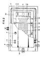
- Fig. 1 is a sectional view of a miniature tipless halogen lamp manufacturing apparatus according to the present invention, including a double-box structure consisting of a hologen gas introducing sealed box A and a heat-sealing sealed box B.
- the halogen gas introducing box A is a corrosion resistant box
- the heat-sealing sealed box B is a high-pressure vessel.
- a halogen gas supply pipe 1 formed of a corrosion-resistant metal for supplying a corrosive gas into the halogen gas introducing sealed box A
- a gas discharge pipe 2 formed of the same material as the halogen gas supply pipe 1
- a pressure gauge 3 for indicating the pressure of the halogen gas prevailing within the halogen gas introducing sealed box A
- a bellows cock 4 for maintaining the perfect airtightness of the halogen gas introducing sealed box A
- fastening boLts 5 corrosion-resistant 0-rings 6 for holding lamp bulbs and for maintaining the perfect airtightness of the halogen gas introducing sealed box A and the heat-sealing sealed box B
- 0-ring fastening rings 7 interposed between the corrosion resistant 0-rings 6 and a corrosion-resistant 0-ring fastening plate 8 for correctly fastening the 0-rings 6
- clamps 9 for airtightly fastening the halogen gas introducing sealed box A and the heat-se
- the fastening plate 8 is provided with a plurality of holes in alignment with the bulbs sealing holes 36 formed in the carbon plate 14 to supply a halogen gas into the lamp bulbs C-8 therethrough.
- a plurality of holes are formed in the heat insulating plate 13 so as to align with the sealing holes 36 of the carbon plate 14.
- thermoelectric thermometer 40 is provided beside the carbon plate 14 with the measuring element, not shown, thereof disposed at a position corresponding to the bead positioned in the lamp bulb C-8 for heat-sealing process as illustrated in Fig. 1.
- the thermoelectric thermometer 40 is connected to a temperature controller, which regulates the temperature of the carbon plate 14.
- Figs. 3 (a) to 3 (h) illustrates a series of processes for assembling the miniature tipless halogen lamp according to the present invention.
- Fig. 3 (a) is a sectional view showing a combination of lead wires C-1 and a bead C-2 put in place on a bead heating carbon plate C-3 and a lead wire holding carbon jig C-4 for fusing the bead C-1 and the bead C-2 after the bead C-2 has been fused and joined to the lead wires C-1.
- Fig. 3 (a) is a sectional view showing a combination of lead wires C-1 and a bead C-2 put in place on a bead heating carbon plate C-3 and a lead wire holding carbon jig C-4 for fusing the bead C-1 and the bead C-2 after the bead C-2 has been fused and joined to the lead wires C-1.
- Fig. 3 (a) is a sectional view showing a combination of lead
- FIG. 3 (c) is a sectional view of an assembly of the lead wires C-1 , the bead C-2 and a filament C-6, in which to fasten the opposite ends of the filament C-6, in which the respective inner ends C-7 of the lead wires C-1 are bent and crimped to fasten the opposite ends of the filament C-6 to the lead wires C-1.
- Fig. 3 (d) is a sectional view of a lamp bulb C-8 having a lens C-9. The lamp bulb C-8 serves also as a gas introducing pipe during the assembling process.
- the lead wires C-1 are held on the bead heating carbon plate C-3 and the lead wire holding carbon jig C-4 and the bead C-2 is set in place on the bead beating carbon plate C-3, as illustrated in Fig. 3 (a).
- the bead heating carbon plate C-3 is heated to fuse the bead C-2 to weld the lead wires C-1 and the bead C-2 together so that an assembly of the lead wires C-1 and the bead C-2 as illustrated in Fig. 3 (b) is produced.
- the respective inner ends namely, the upper ends as viewed in Fig.
- the cock 22 is closed, and then an inert gas is supplied through the inert gas supply pipe 21 into the heat-sealing sealed box B until the internal pressure of the heat-sealing sealed box B reaches a predetermined level. Then, an electric current is supplied to the corrosion-resistant heaters 31 provided within the halogen gas introducing sealed box A to heat the halogen gas supplied into the halogen gas introducing sealed box A in order to raise the pressure of the halogen gas, and thereby the halogen gas is introduced into the lamp bulbs C-8 at the highest possible concentration.
- the lamp bulb C-8 is formed beforehand in a predetermined form having the lens C-9 in the head portion, and the extended upper portion above the position C-1 0, as viewed in Fig. 3 (f), serves as a tip.
- the miniature tipless halogen lamp R is completed by cutting off the upper portion of the lamp bulb C-8 above the position C-10, after completely sealing the lamp bulb C-8 at a position corresponding to the bead C-2.
- the miniature tipless halogen lamp produced by the method of the present invention has a very small external size as compared with the corresponding conventional miniature halogen lamp; for example, the diameter of the smallest conventional minature halogen lamp is about 4.7mm, whereas the diameter of the miniature tipless halogen lamp manufactured by the method of the present invention is as small as about 1.0 mm.
- the invention has been described as applied to manufacturing a halogen lamp, naturally, the present invention is applicable to manufacturing halogen lamps, krypton lamps, xenon lamps and other gas-filled lamps.
- the miniature tipless halogen lamp manufactured by the method of the present invention enables the reduction of the size of apparatus and enables the insertion of the illuminating head employing the miniature tipless halogen lamp of the present invention in a place where is impossible to be illuminated from outside.
- the miniature tipless halogen lamp of the present invention is effectively applicable to diverse purposes in various industrial fields in combination with optical fibers.
Landscapes
- Engineering & Computer Science (AREA)
- Manufacturing & Machinery (AREA)
- Resistance Heating (AREA)
- Vessels And Coating Films For Discharge Lamps (AREA)
Applications Claiming Priority (2)
| Application Number | Priority Date | Filing Date | Title |
|---|---|---|---|
| JP141160/85 | 1985-06-26 | ||
| JP60141160A JPS622447A (ja) | 1985-06-26 | 1985-06-26 | 極小型チツプレスハロゲンランプおよびその製造方法ならびにその装置 |
Publications (2)
| Publication Number | Publication Date |
|---|---|
| EP0205727A2 true EP0205727A2 (fr) | 1986-12-30 |
| EP0205727A3 EP0205727A3 (fr) | 1989-04-12 |
Family
ID=15285525
Family Applications (1)
| Application Number | Title | Priority Date | Filing Date |
|---|---|---|---|
| EP86100266A Withdrawn EP0205727A3 (fr) | 1985-06-26 | 1986-01-10 | Méthode de fabrication d'une lampe à halogène miniature sans queusot et dispositif pour la réaliser |
Country Status (3)
| Country | Link |
|---|---|
| US (1) | US4768985A (fr) |
| EP (1) | EP0205727A3 (fr) |
| JP (1) | JPS622447A (fr) |
Cited By (1)
| Publication number | Priority date | Publication date | Assignee | Title |
|---|---|---|---|---|
| FR2627628A1 (fr) * | 1988-02-18 | 1989-08-25 | Gen Electric | Lampe au xenon convenant plus particulierement aux applications automobiles |
Families Citing this family (10)
| Publication number | Priority date | Publication date | Assignee | Title |
|---|---|---|---|---|
| US5359262A (en) * | 1992-08-31 | 1994-10-25 | Welch Allyn, Inc. | Sub-miniature tungsten halogen lamp with major inert gas and minor halide gas constitutes |
| US5384709A (en) * | 1993-02-23 | 1995-01-24 | Rockwell International Corporation | Miniature fluorescent lamp processing apparatus |
| US6566814B2 (en) | 2001-04-24 | 2003-05-20 | Osram Sylvania Inc. | Induction sealed high pressure lamp bulb |
| US6641449B2 (en) | 2001-04-24 | 2003-11-04 | Osram Sylvania Inc. | High pressure lamp bulb and method of induction sealing |
| JP3594138B2 (ja) * | 2002-01-25 | 2004-11-24 | ノーリツ鋼機株式会社 | ハロゲンランプ |
| CN100375936C (zh) * | 2004-04-26 | 2008-03-19 | 佳能株式会社 | 清洁装置、处理盒、清洁构件和电摄影成像设备 |
| JP4651382B2 (ja) * | 2004-12-28 | 2011-03-16 | 京セラミタ株式会社 | 定着装置のヒータ取付構造 |
| CN103295877B (zh) * | 2013-06-06 | 2015-10-14 | 浙江罗丹照明电器有限公司 | 一种卤素灯排气机 |
| WO2026078245A1 (fr) * | 2024-10-10 | 2026-04-16 | Smolsys Ag | Chambre de traitement pour remplir et sceller un corps en verre creux, procédé associé et capsule en verre |
| EP4726762A1 (fr) * | 2024-10-10 | 2026-04-15 | smolsys AG | Chambre de traitement pour le remplissage et le scellage d'un corps creux en verre, procédé correspondant et capsule en verre |
Family Cites Families (19)
| Publication number | Priority date | Publication date | Assignee | Title |
|---|---|---|---|---|
| US2549359A (en) * | 1945-02-07 | 1951-04-17 | Tung Sol Lamp Works Inc | Machine for sealing in miniature incandescent lamp bulb mounts |
| US2553749A (en) * | 1948-05-05 | 1951-05-22 | Bell Telephone Labor Inc | Sealing fixture for the manufacture of electron discharge devices |
| US3040204A (en) * | 1960-03-04 | 1962-06-19 | Donald J Belknap | Microminiature incandescent lamp |
| US3208812A (en) * | 1963-01-25 | 1965-09-28 | Westinghouse Electric Corp | Process and apparatus for dosing electrical devices |
| JPS4420379Y1 (fr) * | 1966-01-19 | 1969-09-01 | ||
| JPS4420739Y1 (fr) * | 1966-06-06 | 1969-09-04 | ||
| US3460219A (en) * | 1966-10-18 | 1969-08-12 | Ichitaro Fukui | Method of making electric bulbs |
| US3704927A (en) * | 1968-05-27 | 1972-12-05 | Charles L Toomey | Apparatus for making fluorescent lamps |
| US3589790A (en) * | 1968-11-13 | 1971-06-29 | Westinghouse Electric Corp | Method of dosing a halogen cycle incandescent lamp |
| US3698784A (en) * | 1970-06-19 | 1972-10-17 | Hamai Denkyo Kogyo Kk | Manufacturing method for small electric lamps |
| US3716285A (en) * | 1971-08-18 | 1973-02-13 | Westinghouse Electric Corp | Method of manufacturing subminiature electric lamps |
| US3788724A (en) * | 1971-12-07 | 1974-01-29 | F Schenkels | Method of manufacturing gas-filled lamps |
| NL7207324A (fr) * | 1972-05-31 | 1973-12-04 | ||
| US3967871A (en) * | 1972-06-23 | 1976-07-06 | Egyesult Izzolampa Es Villamossagi Resvenytarsasag | Process for manufacturing tubeless vacuum electric discharge lamps |
| GB1434552A (en) * | 1972-07-31 | 1976-05-05 | Hamai Electric Lamp | Manufacture of small bulbs |
| JPS55157858A (en) * | 1979-05-25 | 1980-12-08 | Tokyo Shibaura Electric Co | Method of manufacturing microminiature bulb |
| DE3484658D1 (de) * | 1983-01-12 | 1991-07-11 | Hamai Electric Lamp Co | Verfahren und vorrichtung zur herstellung gasgefuellter lampen kleiner dimension. |
| JPS59128731A (ja) * | 1983-01-12 | 1984-07-24 | Hamai Denkyu Kogyo Kk | 小型ガス入りランプの製造方法 |
| JPS60185357A (ja) * | 1984-03-05 | 1985-09-20 | スタンレー電気株式会社 | ビード封止ガス入り電球の製造装置 |
-
1985
- 1985-06-26 JP JP60141160A patent/JPS622447A/ja active Pending
-
1986
- 1986-01-10 EP EP86100266A patent/EP0205727A3/fr not_active Withdrawn
- 1986-10-14 US US06/918,624 patent/US4768985A/en not_active Expired - Fee Related
Cited By (1)
| Publication number | Priority date | Publication date | Assignee | Title |
|---|---|---|---|---|
| FR2627628A1 (fr) * | 1988-02-18 | 1989-08-25 | Gen Electric | Lampe au xenon convenant plus particulierement aux applications automobiles |
Also Published As
| Publication number | Publication date |
|---|---|
| JPS622447A (ja) | 1987-01-08 |
| US4768985A (en) | 1988-09-06 |
| EP0205727A3 (fr) | 1989-04-12 |
Similar Documents
| Publication | Publication Date | Title |
|---|---|---|
| EP0205727A2 (fr) | Méthode de fabrication d'une lampe à halogène miniature sans queusot et dispositif pour la réaliser | |
| KR100298142B1 (ko) | 밀봉접점장치,밀봉접점장치의제조방법및밀봉방법 | |
| KR100302532B1 (ko) | 캡형전기램프 | |
| US4578043A (en) | Method and apparatus for manufacturing light bulb with bead sealing gas | |
| US6641449B2 (en) | High pressure lamp bulb and method of induction sealing | |
| US2191346A (en) | Electric lamp or similar device and method of manufacture | |
| US4145631A (en) | Incandescent lamp | |
| US4693692A (en) | Apparatus for manufacturing small-size gas-filled lamps | |
| US3460219A (en) | Method of making electric bulbs | |
| JPS643028B2 (fr) | ||
| US3698784A (en) | Manufacturing method for small electric lamps | |
| EP0560420A1 (fr) | Lampe électrique infrarouge à incandescence et procédé pour sa fabrication | |
| US8342899B2 (en) | Method of manufacturing lamp and quartz bulb | |
| US3698785A (en) | Manufacturing method for small electric lamps | |
| CN210511085U (zh) | 一种无烫珠型led灯芯结构 | |
| US4936807A (en) | Method of assembling an electric lamp having a canted arc tube | |
| EP0061747B1 (fr) | Dispositif pour la fabrication de lampes | |
| KR100318815B1 (ko) | 백열전구의 제조장치 및 그 제조방법 | |
| JP2588863B2 (ja) | 白熱電球の製造方法 | |
| JPH08227661A (ja) | アークチューブの製造方法 | |
| SU957320A1 (ru) | Способ изготовлени сверхминиатюрных ламп накаливани | |
| JPH0131663B2 (fr) | ||
| JPH08236016A (ja) | アークチューブにおける2次電極アッシー及び放電ランプバルブ | |
| JPH10112294A (ja) | 回転圧伸成形ラグコネクタを有するランプカプセル | |
| KR920006850Y1 (ko) | 음극선관 봉입장치 |
Legal Events
| Date | Code | Title | Description |
|---|---|---|---|
| PUAI | Public reference made under article 153(3) epc to a published international application that has entered the european phase |
Free format text: ORIGINAL CODE: 0009012 |
|
| AK | Designated contracting states |
Kind code of ref document: A2 Designated state(s): DE FR GB NL |
|
| PUAL | Search report despatched |
Free format text: ORIGINAL CODE: 0009013 |
|
| AK | Designated contracting states |
Kind code of ref document: A3 Designated state(s): DE FR GB NL |
|
| RHK1 | Main classification (correction) |
Ipc: H01K 3/00 |
|
| 17P | Request for examination filed |
Effective date: 19890425 |
|
| 17Q | First examination report despatched |
Effective date: 19910416 |
|
| STAA | Information on the status of an ep patent application or granted ep patent |
Free format text: STATUS: THE APPLICATION IS DEEMED TO BE WITHDRAWN |
|
| 18D | Application deemed to be withdrawn |
Effective date: 19911112 |
|
| RIN1 | Information on inventor provided before grant (corrected) |
Inventor name: HAMAI, JITSUO |