EP0205732A2 - Ensemble d'un essieu de véhicule et d'un support de frein - Google Patents
Ensemble d'un essieu de véhicule et d'un support de frein Download PDFInfo
- Publication number
- EP0205732A2 EP0205732A2 EP86101237A EP86101237A EP0205732A2 EP 0205732 A2 EP0205732 A2 EP 0205732A2 EP 86101237 A EP86101237 A EP 86101237A EP 86101237 A EP86101237 A EP 86101237A EP 0205732 A2 EP0205732 A2 EP 0205732A2
- Authority
- EP
- European Patent Office
- Prior art keywords
- axle
- mounting portion
- support
- plate
- brake
- Prior art date
- Legal status (The legal status is an assumption and is not a legal conclusion. Google has not performed a legal analysis and makes no representation as to the accuracy of the status listed.)
- Granted
Links
Images


Classifications
-
- B—PERFORMING OPERATIONS; TRANSPORTING
- B60—VEHICLES IN GENERAL
- B60T—VEHICLE BRAKE CONTROL SYSTEMS OR PARTS THEREOF; BRAKE CONTROL SYSTEMS OR PARTS THEREOF, IN GENERAL; ARRANGEMENT OF BRAKING ELEMENTS ON VEHICLES IN GENERAL; PORTABLE DEVICES FOR PREVENTING UNWANTED MOVEMENT OF VEHICLES; VEHICLE MODIFICATIONS TO FACILITATE COOLING OF BRAKES
- B60T1/00—Arrangements of braking elements, i.e. of those parts where braking effect occurs specially for vehicles
- B60T1/02—Arrangements of braking elements, i.e. of those parts where braking effect occurs specially for vehicles acting by retarding wheels
- B60T1/06—Arrangements of braking elements, i.e. of those parts where braking effect occurs specially for vehicles acting by retarding wheels acting otherwise than on tread, e.g. employing rim, drum, disc, or transmission or on double wheels
-
- F—MECHANICAL ENGINEERING; LIGHTING; HEATING; WEAPONS; BLASTING
- F16—ENGINEERING ELEMENTS AND UNITS; GENERAL MEASURES FOR PRODUCING AND MAINTAINING EFFECTIVE FUNCTIONING OF MACHINES OR INSTALLATIONS; THERMAL INSULATION IN GENERAL
- F16D—COUPLINGS FOR TRANSMITTING ROTATION; CLUTCHES; BRAKES
- F16D51/00—Brakes with outwardly-movable braking members co-operating with the inner surface of a drum or the like
- F16D51/16—Brakes with outwardly-movable braking members co-operating with the inner surface of a drum or the like shaped as brake-shoes pivoted on a fixed or nearly-fixed axis
- F16D51/18—Brakes with outwardly-movable braking members co-operating with the inner surface of a drum or the like shaped as brake-shoes pivoted on a fixed or nearly-fixed axis with two brake-shoes
-
- F—MECHANICAL ENGINEERING; LIGHTING; HEATING; WEAPONS; BLASTING
- F16—ENGINEERING ELEMENTS AND UNITS; GENERAL MEASURES FOR PRODUCING AND MAINTAINING EFFECTIVE FUNCTIONING OF MACHINES OR INSTALLATIONS; THERMAL INSULATION IN GENERAL
- F16D—COUPLINGS FOR TRANSMITTING ROTATION; CLUTCHES; BRAKES
- F16D51/00—Brakes with outwardly-movable braking members co-operating with the inner surface of a drum or the like
- F16D51/16—Brakes with outwardly-movable braking members co-operating with the inner surface of a drum or the like shaped as brake-shoes pivoted on a fixed or nearly-fixed axis
- F16D51/18—Brakes with outwardly-movable braking members co-operating with the inner surface of a drum or the like shaped as brake-shoes pivoted on a fixed or nearly-fixed axis with two brake-shoes
- F16D51/20—Brakes with outwardly-movable braking members co-operating with the inner surface of a drum or the like shaped as brake-shoes pivoted on a fixed or nearly-fixed axis with two brake-shoes extending in opposite directions from their pivots
- F16D51/22—Brakes with outwardly-movable braking members co-operating with the inner surface of a drum or the like shaped as brake-shoes pivoted on a fixed or nearly-fixed axis with two brake-shoes extending in opposite directions from their pivots mechanically actuated
-
- F—MECHANICAL ENGINEERING; LIGHTING; HEATING; WEAPONS; BLASTING
- F16—ENGINEERING ELEMENTS AND UNITS; GENERAL MEASURES FOR PRODUCING AND MAINTAINING EFFECTIVE FUNCTIONING OF MACHINES OR INSTALLATIONS; THERMAL INSULATION IN GENERAL
- F16D—COUPLINGS FOR TRANSMITTING ROTATION; CLUTCHES; BRAKES
- F16D51/00—Brakes with outwardly-movable braking members co-operating with the inner surface of a drum or the like
- F16D2051/001—Parts or details of drum brakes
- F16D2051/003—Brake supports
-
- F—MECHANICAL ENGINEERING; LIGHTING; HEATING; WEAPONS; BLASTING
- F16—ENGINEERING ELEMENTS AND UNITS; GENERAL MEASURES FOR PRODUCING AND MAINTAINING EFFECTIVE FUNCTIONING OF MACHINES OR INSTALLATIONS; THERMAL INSULATION IN GENERAL
- F16D—COUPLINGS FOR TRANSMITTING ROTATION; CLUTCHES; BRAKES
- F16D2125/00—Components of actuators
- F16D2125/18—Mechanical mechanisms
- F16D2125/20—Mechanical mechanisms converting rotation to linear movement or vice versa
- F16D2125/22—Mechanical mechanisms converting rotation to linear movement or vice versa acting transversely to the axis of rotation
- F16D2125/28—Cams; Levers with cams
- F16D2125/30—Cams; Levers with cams acting on two or more cam followers, e.g. S-cams
Definitions
- the present invention is directed to a vehicle brake support assembly for an internally expanding drum brake assembly and, more specifically, to a vehicle axle and brake support assembly for a drum brake which is utilized in heavy duty trucks and trailers and usually includes a pair of dual web brake shoes and a rotary cam actuator.
- Such brakes usually include a pair of brake shoes having adjacent ends seated for pivotal movement on a cylindrical surface of a pair of anchor pins mounted to a support plate, often referred to as a "spider" which in turn is secured to a vehicle axle or axle housing.
- the support plate is usually of elongate form and a rotatable actuating cam and shaft is mounted to the support plate at the end opposite the anchor pins with the cam disposed between the other ends of the brake shoes.
- rotary movement of the cam causes each of the brake shoes to overcome the biasing force of a return spring and to pivot outwardly about the anchor pins into contact with the radially inwardly facing friction surface of a brake drum secured for rotation with a vehicle wheel.
- the support plate or spider serves as the foundation of the brake assembly and, even though it does not constitute a moving part of the brake assembly, it is subject to and must withstand substantial stress under dynamic braking conditions.
- the rotary cam shaft is usually rotatably mounted to the support plate at a location spaced inwardly from a plane normal to the vehicle axle and passing through the center of the brake shoes and anchor pins. The support plate is therefore subject to substantial twisting forces as it transfers braking torque to the axle under dynamic braking conditions.
- Support plates have therefore traditionally been formed as heavy cast and/or forged members with appropriate areas machined and bored to accommodate the anchor pins and the actuating shaft, and for mounting the support plate to the axle. Such traditional support plates have therefore been expensive to manufacture because of the mass of metal and the machining operations required and increased the weight of the vehicles thereby reducing the economics of operation thereof. Examples of such heavy duty cast and forged support plates or spiders are disclosed in Patents No. 3,144,100, 3,279,569, 3,363,725, and 4.157.747.
- Patents No. 3,385,405, and 4,452,347 disclose the use of two plates secured together to provide a brake support assembly.
- Patents No. 4,200,174 and 4,337,851 each disclose the use of a stamped brake spider or support plate.
- the present invention provides a vehicle axle and brake support assembly for a rotary cam actuated, heavy-duty vehicle brake which is less massive than traditional and state of the art brake support assemblies, is more economical to manufacture and assemble, and is of sufficient strength to withstand substantial braking torque due to the structural form of the metal plate and reinforcement and stiffening thereof.
- the present invention provides a vehicle axle and brake support assembly which includes a vehicle axle having a spindle for rotatably mounting a wheel at each end thereof, a cylindrical surface adjacent each spindle and a brake support assembly at each end of the axle.
- Each brake support assembly includes a stamped metal plate having a substantially planar and circular mounting portion, diametrically opposed, planar first and second support portions substantially parallel to and off-set in opposite directions from the mounting portion, first and second transition sections respectively joining the first and second support portions to the mounting portion, and a pair of reinforcing ribs with each rib extending continuously along opposite edges of the plate from the first support portion across the mounting portion to the second support portion and projecting from the plate in the direction of the spindle at that end of the axle.
- a bracket extends across the second mounting portion of the plate in spaced relation thereto and secured by laterally spaced edges welded to the ribs.
- a pair of laterally spaced apertures are provided through the second mounting portion of the plate.
- a pair of laterally spaced apertures are provided through the bracket with each aperture through the bracket axially aligned with and of the same diameter as one of the apertures through the second support portion of the plate.
- An aperture is provided through the first support portion of the plate.
- a bushing retainer having a cylindrical bore therethrough and a cylindrical external surface concentric with said bore is seated in the aperture through the first support portion of the plate.
- a circular aperture through the mounting portion of the plate and defining an edge between the opposite surfaces of the mounting portion is press-fit to the cylindrical surface of the axle and secured by means of a weld joint between each of the opposite surfaces of the mounting portion of the plate and the cylindrical surface of the axle.
- each bushing having one end seated by interference fit in one of the bores through the second support portion of the plate and the other end of the bushing seated by interference fit with the corresponding axially aligned bore through the bracket.
- Figure 1 is a side view, partly in section of a vehicle axle and brake assembly including the present invention
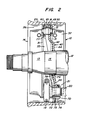
- Figure 2 is a view, partly in section, taken along line II-II of Figure 1
- Figure 3 is a side view of the brake support assembly of Figures 1 and 2
- Figure 4 is a view taken along line IV-IV of Figure 3
- Figure 5 is a view showing the upper end surface of the support assembly of Figure 3.
- a cam actuated brake assembly generally designated by the numeral 10.
- the brake assembly 10 is supported by a brake support assembly 40 rigid with a vehicle axle 12.
- the brake assembly 10 includes a pair of brake shoes 14 each of which is pivotally mounted at one end to a stepped cylindrical anchor pin 15 carried by the brake support assembly 40.
- the anchor pins 15 are each carried by a sleeve type bushing in cylindrical bores provided to the brake support assembly 40, as shown by Figure 2.
- a cam 19 is mounted for rotary movement between the adjacent ends of the brake shoes 14 opposite from the anchor pins 15.
- the brake shoes 14 are each provided with a roller type cam follower 22.
- the cam is non-rotatably secured to a cam shaft 20 mounted to the brake support assembly 40 for rotary movement in a sleeve type bushing 21.
- the cam shaft is rotated by conventional means not shown to rock the cam 19 in a counter-clockwise direction through an arc in the range of 10° to 30°.
- the cam 19 provides an outwardly directed force to the rollers 22 and the brake shoes 14 which cause the brake shoes to pivot about the anchor pins 15. This movement forces the friction linings 24 into contact with the inwardly facing friction surface 26 of a brake drum 25 secured by conventional means to a wheel rotatably mounted to a spindle 13 at the outer end of axle 12.
- a return spring 28 secured at its opposite ends to the brake shoe webs 31.
- the brake shoes 14 are dual web fabricated brake shoes. That is. each brake shoe includes a pair of axially spaced webs 31 secured to a table 32.
- the webs 31 are flat in a radial direction and curved in a longitudinal or circumferential direction.
- the brake shoe table 32 is curved in the circumferential direction and the webs 31 are welded in parallel relation along the interior curved portion of the table. This provides a generally rigid assembly of component parts to which the friction lining pads 24 may be secured by rivets or by chemical bonding.
- the brake support assembly 40 is comprised of a stamped metal plate 42 which includes a substantially planar and circular mounting portion 44 and planar first and second support portions 46 and 48. As shown by Fig. 3, the first and second support portions 46 and 48 are diametrically opposed along the vertical axis. With reference to Figs. 2 and 4, -in the preferred embodiment, the first support portion 46 is axially offset about 7 1/16 inch to the right of the mounting portion 44 and the second support portion 48 is axially offset approximately .459 inch to the left of the mounting portion 44. A circular aperture 45 is provided through the mounting portion 44 and a circular aperture 47 is provided through the first support portion 46.
- a first transition section 5i joins the first support portion 46 to the mounting portion 44 and a second transition section 52 joins the second support portion 48 to the mounting portion 44.
- the stamped metal plate 42 is also formed with a pair of reinforcing ribs 54 and 56 extending continuously along opposite edges of the plate 42 from the first support portion 46 across the mounting portion 44 and substantially across the second support portion 48.
- the reinforcing ribs project from the metal plate 42 in substantially the same direction as the second support portion 48 is offset from the mounting portion 44, i.e. to the left as viewed in Fig. 4.
- linear extent of the projection of the ribs 54 and 56 is minimum in the area of the first support portion 46 and the first transition section 51 and increases as the ribs 54, 56 traverse the mounting portion 44.
- Linear extent means the distance from the edge of the rib measured normal to the surface of the mounting portion 44 of metal plate 42.
- the linear extent of the projection of the ribs increases gradually to a fixed point 58 more than halfway across the mounting portion 44 and increases substantially more rapidly from that point to the second transition section 52.
- the linear extent of rib 54 is shown as increasing over a distance of 3 inches from a minimum linear extent LE min of about 9/16 inch at the first transition section 51 to a linear extent LE of about 3/4 inch at the break point 58 just above the center line of the aperture 45 and then rapidly, over a distance of 3 1/2 inches, increasing to a maximum linear extent LE max of 1 7/16 inches at the beginning of the second transition section 52.
- the slope or rate of displacement of the edge of ribs 54 and 56 relative to the surface 41 of mounting portion 44 is .06 from LE min to LE and the corresponding slope or rate of displacement from LE to LE max is 0.20 or substantially more than two times the rate of displacement from LE min to LE.
- the metal plate 42 with the center planes of the first and second support portions 46 and 48 axially off-set on opposite sides of the mounting portion 44 and connected to the mounting portion 44 by the first and second transition sections 51 and 52 and with the linear extent or axial projection of the reinforcing ribs 54 and 56 increasing from the first transition section 51 to the second transition section 52, provides a relatively lightweight and cost effective integral structural form of substantially uniform thickness throughout which is capable of withstanding the stresses and torque encountered under dynamic braking conditions.
- a bracket 60 is welded at its opposite ends or laterally spaced edges 61 and 62 to the ribs 54 and 56.
- the bracket 60 extends across the second support portion 48 of metal plate 42.
- a pair of bores 64 and 65 in the bracket 60 are respectively axially aligned with bores 49 and 50 provided in the second support portion 48 of metal plate 42.
- a pair of stainless steel sleeve-type bushings 16, only one of which is shown in the drawings, are respectively seated in the bores 49 and 64 and 50 and 65.
- the ends of the sleeve-type bushings 16 of metal plate 42 are press fit to the bores in the bracket 60 and the second mounting portion 48 to secure the bushings 16 in place and thereby support the stepped cylindrical anchor pins 15.
- An aperture 47 provided in the first support portion 46 receives and mounts a bushing retainer 70 having a sleeve-type bushing 21 seated internally of a bore 71.
- the bushing retainer 70 is formed with first and second external cylindrical surfaces 72, 74 concentric with the bore 71 and separated by a shoulder 75.
- the smaller diameter external surface 72 is dimensioned to fit in the aperture 47 where it is secured to the first support portion 46 of metal plate 42 by a plurality of welds 76.
- the sleeve-type bushing 21 internal of bushing retainer 70 rotatably mounts the shaft 20 of cam 19.
- the metal plate 42 is formed as a stamped part from a blank cut from 3/8" thick SAE 50 XLF, high-strength, low alloy. hot rolled steel sheet strip with the mounting portion 44, both support portions 46 and 48, both transition sections 51 and 52 and both reinforcing ribs 54 and 56 all of substantially the same thickness.
- the aperture 45 in the mounting portion 44 and the aperture 47 in the first support portion 46 are formed during the stamping operation and the dimensions of the stamped apertures 45 and 47 are held within tolerances so as to insure satisfactory fit to the cylindrical surface 14 of axle 12 and to the bushing retainer 70 with no additional machining required.
- the aperture resulting from stamping and forming the metal plate 42 defines an edge 45 between the opposite surfaces 41 and 43 of the mounting portion 44.
- the bores 49 and 50 at the second support portion 48 of metal plate 42 are rough punched in the stamping operation and machined with the bracket bores 64 and 65 after the bracket 60 has been welded to the reinforcing ribs 54 and 56.
- the bracket 60 is preferably stamped from a blank cut from 5/16" thick hot rolled steel sheet strip with the bores 64 and 65 rough punched through the blank.
- the second support portion 48 of the metal plate 42 and the bracket 60 are also pressed to provide a plurality of bosses 57 and 77.
- the bosses 57 and 77 are raised from opposite sides of the second support portion 48 of metal plate 42 and the bracket 60 in the brake support assembly 40.
- the bosses 57 and 77 extend about .05 inch from the surface of the second support portion 48 and the bracket 60 respectively and extend a greater axial distance than the ends of the sleeve-type bushings 16 in bores 49 and 64 and bores 50 and 65.
- a pair of aligned and oppositely disposed bosses 57 and 77 abut the internal spaced surfaces 33 of the brake shoe webs 31 of each brake shoe l4 and provide a bearing surface spacing the brake shoe webs 31 away from the ends of the sleeve-type bushings 16 as well as the second support portion 48 of the metal plate 42 and the bracket 60.
- the brake support assembly 40 is pressed onto the cylindrical surface 14 adjacent the spindle 13 of axle 12 with the mounting portion 44 of metal plate 42 extending substantially normal to the longitudinal axis of axle 12 and with the aperture edge 45 seated on the cylindrical surface 14.
- Continuous weld joints 78 and 79 are then provided between the opposite surfaces 41 and 43 of the mounting portion 44 of metal plate 42 and the cylindrical surface 14 of axle 12.
- the weld joints 78 and 79 not only secure the brake support assembly 40 to the axle l2, they also stiffen the brake support assembly 40 and together with the structural form of the stamped metal plate 42 provide a fabricated brake support assembly 40 of sufficient structural integrity to withstand the stresses and torque encountered under dynamic braking conditions without the use of a heavy cast or forged member and with a minimum of machining operations thereby rendering operation of the vehicle and the manufacturing process more economical.
Landscapes
- Engineering & Computer Science (AREA)
- General Engineering & Computer Science (AREA)
- Mechanical Engineering (AREA)
- Transportation (AREA)
- Braking Arrangements (AREA)
Applications Claiming Priority (2)
| Application Number | Priority Date | Filing Date | Title |
|---|---|---|---|
| US748900 | 1985-06-26 | ||
| US06/748,900 US4854427A (en) | 1985-06-26 | 1985-06-26 | Vehicle axle and brake support assembly |
Publications (3)
| Publication Number | Publication Date |
|---|---|
| EP0205732A2 true EP0205732A2 (fr) | 1986-12-30 |
| EP0205732A3 EP0205732A3 (en) | 1987-08-26 |
| EP0205732B1 EP0205732B1 (fr) | 1991-01-02 |
Family
ID=25011404
Family Applications (1)
| Application Number | Title | Priority Date | Filing Date |
|---|---|---|---|
| EP86101237A Expired EP0205732B1 (fr) | 1985-06-26 | 1986-01-30 | Ensemble d'un essieu de véhicule et d'un support de frein |
Country Status (8)
| Country | Link |
|---|---|
| US (1) | US4854427A (fr) |
| EP (1) | EP0205732B1 (fr) |
| JP (1) | JPS624936A (fr) |
| BR (1) | BR8601235A (fr) |
| CA (1) | CA1255238A (fr) |
| DE (2) | DE3676352D1 (fr) |
| IN (1) | IN165952B (fr) |
| MX (1) | MX163896B (fr) |
Cited By (1)
| Publication number | Priority date | Publication date | Assignee | Title |
|---|---|---|---|---|
| AU637622B2 (en) * | 1989-08-08 | 1993-06-03 | Gordon Joseph Taylor | Brake shoe roller assembly |
Families Citing this family (11)
| Publication number | Priority date | Publication date | Assignee | Title |
|---|---|---|---|---|
| CA2030315A1 (fr) * | 1990-06-26 | 1991-12-27 | Sung J. Cho | Systeme de freinage a joint a croisillon |
| US5182484A (en) * | 1991-06-10 | 1993-01-26 | Rockwell International Corporation | Releasing linear actuator |
| US5590742A (en) * | 1995-06-07 | 1997-01-07 | Itt Automotive, Inc. | Stamped caliper adapter |
| US6089361A (en) * | 1997-11-25 | 2000-07-18 | Dana Corporation | S-cam spider bushing cartridge |
| US7055662B1 (en) * | 1999-12-23 | 2006-06-06 | Dana Corporation | Vehicle axle beam and brake assembly |
| JP4597345B2 (ja) * | 2000-10-24 | 2010-12-15 | 豊生ブレーキ工業株式会社 | ドラムブレーキ |
| US7708124B1 (en) | 2005-11-10 | 2010-05-04 | Rackers Mitchell Ldquo Mitch R | Anchoring sleeve assembly and method of use |
| WO2009111006A2 (fr) * | 2008-03-05 | 2009-09-11 | Tuthill Corporation | Système de suspension avec essieu embouti et supports de bras soudés et procédé de fabrication associé |
| US20100193303A1 (en) * | 2009-02-05 | 2010-08-05 | Bendix Spicer Foundation Brake Llc | Brake spider weldment and anchor pin assembly |
| US9133898B2 (en) * | 2013-08-16 | 2015-09-15 | Bendix Spicer Foundation Brake Llc | Heavy duty stamped spider |
| US9303703B2 (en) * | 2014-07-09 | 2016-04-05 | Bendix Spicer Foundation Brake Llc | Bracket assembly for mounting a brake assembly and brake actuator |
Family Cites Families (5)
| Publication number | Priority date | Publication date | Assignee | Title |
|---|---|---|---|---|
| US3144100A (en) * | 1963-02-27 | 1964-08-11 | Kay Brunner Steel Products Inc | Vehicle braking system |
| US4337851A (en) * | 1980-05-23 | 1982-07-06 | Pringle William L | Brake support assembly |
| CA1169367A (fr) * | 1981-04-30 | 1984-06-19 | Leonard C. Dozier | Brassure de frein |
| US4452347A (en) * | 1981-04-30 | 1984-06-05 | Rockwell International Corporation | Brake spider |
| US4445597A (en) * | 1982-06-17 | 1984-05-01 | Eaton Corporation | Spider assembly for drum brake |
-
1985
- 1985-06-26 US US06/748,900 patent/US4854427A/en not_active Expired - Lifetime
-
1986
- 1986-01-27 IN IN75/DEL/86A patent/IN165952B/en unknown
- 1986-01-30 EP EP86101237A patent/EP0205732B1/fr not_active Expired
- 1986-01-30 DE DE8686101237T patent/DE3676352D1/de not_active Expired - Fee Related
- 1986-01-30 DE DE198686101237T patent/DE205732T1/de active Pending
- 1986-01-31 CA CA000500858A patent/CA1255238A/fr not_active Expired
- 1986-02-24 JP JP61037533A patent/JPS624936A/ja active Granted
- 1986-03-20 BR BR8601235A patent/BR8601235A/pt not_active IP Right Cessation
- 1986-06-24 MX MX2908A patent/MX163896B/es unknown
Cited By (1)
| Publication number | Priority date | Publication date | Assignee | Title |
|---|---|---|---|---|
| AU637622B2 (en) * | 1989-08-08 | 1993-06-03 | Gordon Joseph Taylor | Brake shoe roller assembly |
Also Published As
| Publication number | Publication date |
|---|---|
| DE205732T1 (de) | 1987-04-30 |
| CA1255238A (fr) | 1989-06-06 |
| JPH0461216B2 (fr) | 1992-09-30 |
| DE3676352D1 (de) | 1991-02-07 |
| EP0205732B1 (fr) | 1991-01-02 |
| BR8601235A (pt) | 1987-03-04 |
| JPS624936A (ja) | 1987-01-10 |
| US4854427A (en) | 1989-08-08 |
| MX163896B (es) | 1992-06-30 |
| IN165952B (fr) | 1990-02-17 |
| EP0205732A3 (en) | 1987-08-26 |
Similar Documents
| Publication | Publication Date | Title |
|---|---|---|
| EP0205659B1 (fr) | Support de frein d'un véhicule | |
| US4452347A (en) | Brake spider | |
| US4854427A (en) | Vehicle axle and brake support assembly | |
| US6279695B1 (en) | Integrated axle spindle and brake spider | |
| US5325945A (en) | Vehicle brake support assembly | |
| CA2023237C (fr) | Frein avec portee d'ancrage sur plateau de frein | |
| US4858729A (en) | Brake support assembly | |
| US20060016652A1 (en) | Cam actuated drum brake | |
| CA1074715A (fr) | Freins | |
| AU2014274303B2 (en) | Hinged table brake shoe | |
| CA2729221C (fr) | Ame double de segment de frein a large ecartement coude | |
| EP0064215B1 (fr) | Support de frein | |
| CA1076494A (fr) | Freins | |
| US5695025A (en) | Steering axle brake assembly | |
| EP0078115B1 (fr) | Frein à tambour à sabot d'écartement | |
| GB2087493A (en) | Brake spider with integral pivot posts |
Legal Events
| Date | Code | Title | Description |
|---|---|---|---|
| PUAI | Public reference made under article 153(3) epc to a published international application that has entered the european phase |
Free format text: ORIGINAL CODE: 0009012 |
|
| AK | Designated contracting states |
Kind code of ref document: A2 Designated state(s): BE DE FR GB IT NL SE |
|
| TCNL | Nl: translation of patent claims filed | ||
| ITCL | It: translation for ep claims filed |
Representative=s name: SOCIETA' ITALIANA BREVETTI S.P.A. |
|
| EL | Fr: translation of claims filed | ||
| DET | De: translation of patent claims | ||
| PUAL | Search report despatched |
Free format text: ORIGINAL CODE: 0009013 |
|
| AK | Designated contracting states |
Kind code of ref document: A3 Designated state(s): BE DE FR GB IT NL SE |
|
| 17P | Request for examination filed |
Effective date: 19880203 |
|
| 17Q | First examination report despatched |
Effective date: 19890118 |
|
| GRAA | (expected) grant |
Free format text: ORIGINAL CODE: 0009210 |
|
| AK | Designated contracting states |
Kind code of ref document: B1 Designated state(s): BE DE FR GB IT NL SE |
|
| REF | Corresponds to: |
Ref document number: 3676352 Country of ref document: DE Date of ref document: 19910207 |
|
| ET | Fr: translation filed | ||
| ITF | It: translation for a ep patent filed | ||
| PLBE | No opposition filed within time limit |
Free format text: ORIGINAL CODE: 0009261 |
|
| STAA | Information on the status of an ep patent application or granted ep patent |
Free format text: STATUS: NO OPPOSITION FILED WITHIN TIME LIMIT |
|
| 26N | No opposition filed | ||
| EAL | Se: european patent in force in sweden |
Ref document number: 86101237.5 |
|
| PGFP | Annual fee paid to national office [announced via postgrant information from national office to epo] |
Ref country code: FR Payment date: 19961216 Year of fee payment: 12 |
|
| PGFP | Annual fee paid to national office [announced via postgrant information from national office to epo] |
Ref country code: NL Payment date: 19961223 Year of fee payment: 12 Ref country code: BE Payment date: 19961223 Year of fee payment: 12 |
|
| PG25 | Lapsed in a contracting state [announced via postgrant information from national office to epo] |
Ref country code: FR Free format text: THE PATENT HAS BEEN ANNULLED BY A DECISION OF A NATIONAL AUTHORITY Effective date: 19980131 Ref country code: BE Free format text: LAPSE BECAUSE OF NON-PAYMENT OF DUE FEES Effective date: 19980131 |
|
| BERE | Be: lapsed |
Owner name: ROCKWELL INTERNATIONAL CORP. Effective date: 19980131 |
|
| PG25 | Lapsed in a contracting state [announced via postgrant information from national office to epo] |
Ref country code: NL Free format text: LAPSE BECAUSE OF NON-PAYMENT OF DUE FEES Effective date: 19980801 |
|
| NLV4 | Nl: lapsed or anulled due to non-payment of the annual fee |
Effective date: 19980801 |
|
| REG | Reference to a national code |
Ref country code: FR Ref legal event code: ST |
|
| REG | Reference to a national code |
Ref country code: GB Ref legal event code: IF02 |
|
| PGFP | Annual fee paid to national office [announced via postgrant information from national office to epo] |
Ref country code: SE Payment date: 20030102 Year of fee payment: 18 |
|
| PGFP | Annual fee paid to national office [announced via postgrant information from national office to epo] |
Ref country code: GB Payment date: 20030122 Year of fee payment: 18 |
|
| PGFP | Annual fee paid to national office [announced via postgrant information from national office to epo] |
Ref country code: DE Payment date: 20030131 Year of fee payment: 18 |
|
| PG25 | Lapsed in a contracting state [announced via postgrant information from national office to epo] |
Ref country code: GB Free format text: LAPSE BECAUSE OF NON-PAYMENT OF DUE FEES Effective date: 20040130 |
|
| PG25 | Lapsed in a contracting state [announced via postgrant information from national office to epo] |
Ref country code: SE Free format text: LAPSE BECAUSE OF NON-PAYMENT OF DUE FEES Effective date: 20040131 |
|
| PG25 | Lapsed in a contracting state [announced via postgrant information from national office to epo] |
Ref country code: DE Free format text: LAPSE BECAUSE OF NON-PAYMENT OF DUE FEES Effective date: 20040803 |
|
| EUG | Se: european patent has lapsed | ||
| GBPC | Gb: european patent ceased through non-payment of renewal fee |
Effective date: 20040130 |
|
| PG25 | Lapsed in a contracting state [announced via postgrant information from national office to epo] |
Ref country code: IT Free format text: LAPSE BECAUSE OF NON-PAYMENT OF DUE FEES;WARNING: LAPSES OF ITALIAN PATENTS WITH EFFECTIVE DATE BEFORE 2007 MAY HAVE OCCURRED AT ANY TIME BEFORE 2007. THE CORRECT EFFECTIVE DATE MAY BE DIFFERENT FROM THE ONE RECORDED. Effective date: 20050130 |