EP0206067A1 - Structure active catalytiquement constituée d'éléments individuels et procédé pour la préparation de ces éléments - Google Patents
Structure active catalytiquement constituée d'éléments individuels et procédé pour la préparation de ces éléments Download PDFInfo
- Publication number
- EP0206067A1 EP0206067A1 EP86107810A EP86107810A EP0206067A1 EP 0206067 A1 EP0206067 A1 EP 0206067A1 EP 86107810 A EP86107810 A EP 86107810A EP 86107810 A EP86107810 A EP 86107810A EP 0206067 A1 EP0206067 A1 EP 0206067A1
- Authority
- EP
- European Patent Office
- Prior art keywords
- ribs
- individual elements
- base plate
- flow
- individual
- Prior art date
- Legal status (The legal status is an assumption and is not a legal conclusion. Google has not performed a legal analysis and makes no representation as to the accuracy of the status listed.)
- Withdrawn
Links
Images




Classifications
-
- B—PERFORMING OPERATIONS; TRANSPORTING
- B01—PHYSICAL OR CHEMICAL PROCESSES OR APPARATUS IN GENERAL
- B01J—CHEMICAL OR PHYSICAL PROCESSES, e.g. CATALYSIS OR COLLOID CHEMISTRY; THEIR RELEVANT APPARATUS
- B01J19/00—Chemical, physical or physico-chemical processes in general; Their relevant apparatus
- B01J19/24—Stationary reactors without moving elements inside
- B01J19/248—Reactors comprising multiple separated flow channels
- B01J19/249—Plate-type reactors
-
- F—MECHANICAL ENGINEERING; LIGHTING; HEATING; WEAPONS; BLASTING
- F28—HEAT EXCHANGE IN GENERAL
- F28F—DETAILS OF HEAT-EXCHANGE AND HEAT-TRANSFER APPARATUS, OF GENERAL APPLICATION
- F28F21/00—Constructions of heat-exchange apparatus characterised by the selection of particular materials
- F28F21/04—Constructions of heat-exchange apparatus characterised by the selection of particular materials of ceramic; of concrete; of natural stone
-
- B—PERFORMING OPERATIONS; TRANSPORTING
- B01—PHYSICAL OR CHEMICAL PROCESSES OR APPARATUS IN GENERAL
- B01J—CHEMICAL OR PHYSICAL PROCESSES, e.g. CATALYSIS OR COLLOID CHEMISTRY; THEIR RELEVANT APPARATUS
- B01J2219/00—Chemical, physical or physico-chemical processes in general; Their relevant apparatus
- B01J2219/24—Stationary reactors without moving elements inside
- B01J2219/2401—Reactors comprising multiple separate flow channels
- B01J2219/245—Plate-type reactors
- B01J2219/2451—Geometry of the reactor
- B01J2219/2453—Plates arranged in parallel
-
- B—PERFORMING OPERATIONS; TRANSPORTING
- B01—PHYSICAL OR CHEMICAL PROCESSES OR APPARATUS IN GENERAL
- B01J—CHEMICAL OR PHYSICAL PROCESSES, e.g. CATALYSIS OR COLLOID CHEMISTRY; THEIR RELEVANT APPARATUS
- B01J2219/00—Chemical, physical or physico-chemical processes in general; Their relevant apparatus
- B01J2219/24—Stationary reactors without moving elements inside
- B01J2219/2401—Reactors comprising multiple separate flow channels
- B01J2219/245—Plate-type reactors
- B01J2219/2451—Geometry of the reactor
- B01J2219/2456—Geometry of the plates
- B01J2219/2458—Flat plates, i.e. plates which are not corrugated or otherwise structured, e.g. plates with cylindrical shape
-
- B—PERFORMING OPERATIONS; TRANSPORTING
- B01—PHYSICAL OR CHEMICAL PROCESSES OR APPARATUS IN GENERAL
- B01J—CHEMICAL OR PHYSICAL PROCESSES, e.g. CATALYSIS OR COLLOID CHEMISTRY; THEIR RELEVANT APPARATUS
- B01J2219/00—Chemical, physical or physico-chemical processes in general; Their relevant apparatus
- B01J2219/24—Stationary reactors without moving elements inside
- B01J2219/2401—Reactors comprising multiple separate flow channels
- B01J2219/245—Plate-type reactors
- B01J2219/2461—Heat exchange aspects
- B01J2219/2462—Heat exchange aspects the reactants being in indirect heat exchange with a non reacting heat exchange medium
-
- B—PERFORMING OPERATIONS; TRANSPORTING
- B01—PHYSICAL OR CHEMICAL PROCESSES OR APPARATUS IN GENERAL
- B01J—CHEMICAL OR PHYSICAL PROCESSES, e.g. CATALYSIS OR COLLOID CHEMISTRY; THEIR RELEVANT APPARATUS
- B01J2219/00—Chemical, physical or physico-chemical processes in general; Their relevant apparatus
- B01J2219/24—Stationary reactors without moving elements inside
- B01J2219/2401—Reactors comprising multiple separate flow channels
- B01J2219/245—Plate-type reactors
- B01J2219/2476—Construction materials
- B01J2219/2477—Construction materials of the catalysts
- B01J2219/2479—Catalysts coated on the surface of plates or inserts
-
- B—PERFORMING OPERATIONS; TRANSPORTING
- B01—PHYSICAL OR CHEMICAL PROCESSES OR APPARATUS IN GENERAL
- B01J—CHEMICAL OR PHYSICAL PROCESSES, e.g. CATALYSIS OR COLLOID CHEMISTRY; THEIR RELEVANT APPARATUS
- B01J2219/00—Chemical, physical or physico-chemical processes in general; Their relevant apparatus
- B01J2219/24—Stationary reactors without moving elements inside
- B01J2219/2401—Reactors comprising multiple separate flow channels
- B01J2219/245—Plate-type reactors
- B01J2219/2476—Construction materials
- B01J2219/2483—Construction materials of the plates
- B01J2219/2487—Ceramics
-
- B—PERFORMING OPERATIONS; TRANSPORTING
- B01—PHYSICAL OR CHEMICAL PROCESSES OR APPARATUS IN GENERAL
- B01J—CHEMICAL OR PHYSICAL PROCESSES, e.g. CATALYSIS OR COLLOID CHEMISTRY; THEIR RELEVANT APPARATUS
- B01J2219/00—Chemical, physical or physico-chemical processes in general; Their relevant apparatus
- B01J2219/24—Stationary reactors without moving elements inside
- B01J2219/2401—Reactors comprising multiple separate flow channels
- B01J2219/245—Plate-type reactors
- B01J2219/2491—Other constructional details
-
- B—PERFORMING OPERATIONS; TRANSPORTING
- B01—PHYSICAL OR CHEMICAL PROCESSES OR APPARATUS IN GENERAL
- B01J—CHEMICAL OR PHYSICAL PROCESSES, e.g. CATALYSIS OR COLLOID CHEMISTRY; THEIR RELEVANT APPARATUS
- B01J2219/00—Chemical, physical or physico-chemical processes in general; Their relevant apparatus
- B01J2219/24—Stationary reactors without moving elements inside
- B01J2219/2401—Reactors comprising multiple separate flow channels
- B01J2219/245—Plate-type reactors
- B01J2219/2491—Other constructional details
- B01J2219/2492—Assembling means
- B01J2219/2493—Means for assembling plates together, e.g. sealing means, screws, bolts
-
- B—PERFORMING OPERATIONS; TRANSPORTING
- B01—PHYSICAL OR CHEMICAL PROCESSES OR APPARATUS IN GENERAL
- B01J—CHEMICAL OR PHYSICAL PROCESSES, e.g. CATALYSIS OR COLLOID CHEMISTRY; THEIR RELEVANT APPARATUS
- B01J35/00—Catalysts, in general, characterised by their form or physical properties
- B01J35/30—Catalysts, in general, characterised by their form or physical properties characterised by their physical properties
- B01J35/34—Mechanical properties
- B01J35/38—Abrasion or attrition resistance
Definitions
- the invention is directed to a device for treating flowing media, consisting of an optionally ceramic structure which is provided with flow channels.
- moldings are generally used that divide these streams, ensure the largest possible contact surface and regulate the flow conditions.
- a variant of known shaped bodies for this purpose consists of monolithic shaped bodies with honeycomb structures and thus continuous flow channels that divide and direct the flow.
- honeycomb bodies often consist of ceramic materials that are shaped, dried and fired in the extrusion process. Drying and firing of such ceramic moldings are costly and time-consuming and - because of the large number of walls and air channels - difficult to control. This method of manufacturing such honeycomb bodies limits the possibility of the surface configuration channel walls on structures in the direction of the strand, because only they can be formed by extrusion.
- bulk solids are used in the form of balls, rings and similar geometric shapes. These bulk solids enable a good exchange of contact with the media to be treated, but lead to the decisive disadvantage that they cause a relatively high flow resistance, which is hardly predictable and can only be varied within narrow limits.
- the invention sees the solution to this complex problem in a device of the type described at the outset in a structure which consists of a plurality of individual elements, which has a base plate with parallel ribs spaced apart on one surface and which is arranged in the same direction in a three-dimensional arrangement are composed of a structure, the flow channels from the base plate and the ribs of adjacent individual elements are formed.
- Such individual elements which can be produced in comparatively small geometric dimensions, can easily be assembled in a predetermined, ordered form to form a geometric body of any size, the number of individual elements arranged side by side, one above the other and one behind the other in the direction of flow entirely depending on the requirements of the individual case can be coordinated.
- the individual flow channels are formed between the ribs and base plates of the adjacent individual elements. The more such individual elements are arranged side by side and one above the other, the greater the number of flow channels, the length of which in turn is determined by the length of the individual elements and the number of element packages connected in series in the flow direction.
- the individual element can also consist of a catalytically active material.
- a mechanically strong carrier layer and / or a carrier layer which is particularly resistant to temperature and / or temperature changes and a porous surface layer.
- Several layers can be produced in successive pressing processes and thus compressed and then fired together. It is also conceivable to produce such multiple layers in several work steps and intermediate firing processes, for example by glazes that the material systems can be easily adapted to any desired application.
- the solid carrier layer has a rough surface. This favors the adherence of a superficial coating or the direct coating of the solid support layer with a catalyst material or the like.
- the invention further provides for the individual elements to be provided with a surface structure running at an angle to the direction of flow.
- a surface structure running at an angle to the direction of flow.
- the surface of the individual element can have cams, webs, depressions or the like. It is also within the scope of the invention to provide the base plate and / or the ribs or webs of the individual elements with window-like openings. All measures of this type are outstandingly suitable for influencing the flow of the medium in any desired manner and thereby improving the desired reactivity of the system, and it is possible for both longitudinal and transverse flows to be operated in one system.
- the ribs of the base plate have the same height and are arranged at the same distance, the one outer rib along a longitudinal edge of the base plate and the other outer rib around one Rib distance from the other longitudinal edge is arranged. This ensures that all flow channels have the same clear cross section and that the flow channels are largely sealed on all sides. Similarly, the flow channel cross-sections can - the desired flow resistance to be adjusted.
- the invention also deals with the implementation of a device from a plurality of individual, individual elements by providing in a further embodiment that individual elements of different shape and / or strength and / or surface design in the flow direction one behind the other and / or side by side in the structure are arranged.
- the adaptability of a reaction system formed in this way from numerous individual elements is practically unlimited. It is within the scope of this general inventive concept that individual elements of particularly high wear resistance are arranged at desired positions in the upstream region. It has been found that in the inflow area the media entrained by the abrasive contaminants cause considerable signs of wear. It is a particularly great advantage of the device constructed according to the invention that areas which are exposed to particularly high wear during operation can be replaced by new individual elements without it being necessary to replace an entire structure.
- a device on the inflow side of the structure for separating mechanical contaminants from the flowing media.
- This can be a sieve, a filter or the like, or a layer of particularly wear-resistant individual element packages in the form on which the invention is based.
- the three-dimensionally arranged individual elements can be enclosed by a housing to construct the entire device.
- This can be made of a heat-resistant material and ensures the spatial cohesion of the more or less numerous individual elements in the desired shape.
- Another alternative is provided by the invention in such a way that the three-dimensionally arranged individual elements are combined in and / or transverse to the flow direction of holding elements. This can be holding straps or the like.
- the invention extends not only to the geometric conception of a new basic element and the principle of the modular construction or connection method, but also to the construction of layers of different materials with specific functions in the reaction system, which can be realized in the pressing process, and to the surface configurations possible in the same production process with raised or recessed geometric structures such as ribs or patterns, which can be arranged transversely or at an angle to the direction of flow, and with windows or openings in the described base plate and the longitudinal ribs or webs.
- the geometrical surfaces of the flow channels can be varied within wide limits and adapted to the requirements of the application.
- the foaming or spraying of reactive substances on both the non- as well as on the fired individual body and any necessary post-treatments are easily possible, as is the application of glazes.
- the modular design also allows the installation of individual elements that consist of different materials or are provided with different reactive or catalytic coatings, so that devices can be built that would not be possible in this way with honeycomb monolithic geometries in this range.
- Such an extension and modification of the principle according to the invention results in a further embodiment of the invention in that the longitudinal axes of the ribs have the same distances from one another over the length of the individual elements and that the outer surfaces of the ribs are at least partially inclined with respect to the average longitudinal axis.
- the mean longitudinal axis is understood to mean the main direction of extension of the ribs, which do not have an actual longitudinal axis, unless they are straight throughout.
- the ribs are corrugated, the corrugation of all the ribs running at a distance from each other swiveling out uniformly in order to maintain the same distance between the central axes of the ribs.
- a second particularly advantageous embodiment by means of which the flow conditions can be influenced further, results from the fact that the ribs with longitudinal central axes running parallel to one another have a thickness that changes in the longitudinal direction.
- the change in thickness can take place in stages, for example, starting from a greater thickness at the inlet, a one-time or multiple r graded change in thickness. Instead, the thickness can decrease continuously from one end to the other.
- the individual element 1 is comparatively thin-walled, and that the wall thickness can go to the lower limit of the desired mechanical strength.
- the individual element 1 consists of a flat base plate 2 with the length x and the width y.
- four ribs 5 arranged parallel to one another are provided on the surface 3 of this base plate 2 and have the same height z with respect to the lower surface 6 of the base plate 2.
- One outer rib 5 1 runs along the lateral longitudinal edge 7 of the base plate 2, the other outer rib 5 "runs at a distance w from the other longitudinal edge 8 of the base plate 2. This dimension w corresponds to the respective distances between two ribs 5.
- the base body 1 can consist of a single carrier layer 9, which may consist of a self-catalytically active material.
- the embodiment according to FIG. 3 consists of a solid inner carrier layer 10 and a porous surface layer 11, which is located both on the surface 3 and the lower surface 6 and on the ribs 5 of the individual element 1. Possibly.
- This porous surface layer can also be located only on the ribs 5 or only on the base plate 2.
- the base plate 2 has a superficial structure of intersecting ribs 12 which run at an angle to the flow direction 13 of the medium to be treated.
- window-like openings 14, which have a rectangular cross section, are arranged in the base plate 2.
- the openings 15 used in the embodiment according to FIG. 7 have a triangular cross section, the tip 16 of the opening cross section pointing in the flow direction 13. The most arbitrary cross sections and sizes are conceivable for these openings 14.
- FIG. 6 shows that the window-like openings 14 are laterally offset in the longitudinal direction, which corresponds to the direction of flow 13.
- the window-like openings 15 are displaced in the flow channels arranged next to one another.
- transverse ribs 25 extending transversely to the flow direction 13 are arranged in the space between two ribs 5, which extend both on the surface 3 of the base plate and on the side walls of the ribs 5.
- the embodiment according to FIG. 9 is characterized by window-like interruptions 26 arranged in the ribs 5.
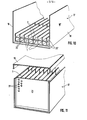
- FIGS. 10 and 11 only show an example of a structure to be designed from a large number of individual elements 1, in this embodiment within a housing 17 made of e.g. heat-resistant material.
- the clear internal dimensions of this housing 17 correspond to the grid dimension of the individual elements 1.
- the housing 17, as can be seen in FIGS. 10 and 11, is open at the top and is closed by a cover 19 which overlaps the two side walls 18.
- One side wall 18 'of the housing 17 closes the respective outer flow channels 20' from the individual elements 1 laterally.
- the base plate 2 of each individual element 1 of the module system serves to complete the corresponding flow channels 20 of the individual elements 1 located below them.
- the flow channels 20 between the ribs 5 of the individual elements 1 lying uppermost in the stack are closed by the cover 19.
- the base plate 2 of each superordinate individual element 1 closes the flow channels 20 of each individual element 1 located below it.
- the front side of the housing 17 is closed by the plate 21, which is provided with a perforation 22 over its entire surface.
- the medium to be treated enters the housing 17 on the inlet side and exits again on the opposite side (not shown).
- the outer walls of the housing could also consist of a wire mesh or e.g. ceramic perforated plates or similar Moldings or materials.
- the inventive design of the device from a variety of individual elements comes, among other things. considered for cooling, heating and / or cleaning of gases and liquids, e.g. in reaction systems and for catalyst systems.
- FIGS. 12 and 13 merely show another example of a structure to be designed from a large number of individual elements 1, in this embodiment within a housing 17 made of e.g. heat-resistant material.
- the clear internal dimensions of this housing 17 correspond to the grid dimension of the individual elements 1.
- the housing 17, as can be seen in FIGS. 12 and 13, is open at the top and is closed by a cover 19 which overlaps the two side walls 18.
- One side wall 18 'of the housing 17 closes the respective outer flow channels 20' from the individual elements 1 laterally.
- the base plate 2 of each individual element 1 of the module system serves to complete the corresponding flow channels 20 of the individual elements 1 located below them.
- the flow channels 20 between the ribs 5 of the individual elements 1 lying uppermost in the stack are closed by the cover 19.
- the base plate 2 of each superordinate individual element 1 closes the flow channels 20 of each individual element 1 located below it.
- the end face of the housing 17 is closed by the plate 21, which is provided with a perforation 22 over its entire surface.
- the medium to be treated enters the housing 17 on the inlet side and exits again on the opposite side (not shown).
- the outer walls of the housing could also consist of a wire mesh or e.g. ceramic perforated plates or similar molded parts or materials.
- the individual elements 1 are comparatively thin-walled, and the wall thickness can go to the lower limit of the desired mechanical strength.
- the single element 1 consists of a flat base plate 2, on each of which four ribs 5 are provided in the illustrated exemplary embodiments, all of which have the same height relative to the lower surface of the base plate 2.
- One outer rib 5 1 runs along the lateral longitudinal edge 7 of the base plate 2, the other outer rib 5 "runs in the embodiments according to FIGS. 14 and 16 at a distance from the other longitudinal edge 8 of the base plate. This distance corresponds to the respective distances between two Ribs 5.
- the longitudinal central axes of all the ribs 5, 5 ', 5 are arranged parallel to one another.
- the thicknesses of the ribs change from a value d 1 on the input side to a value d 2 on the output side, the change in thickness
- a single block 23 is formed on the edge 8, the thickness of which is transverse to the longitudinal direction (d 1 - d 2 ) / 2.
- the thickness of the ribs changes continuously from the input value d 1 to the output value d 2 , with the result that the rib 5 "is not arranged at a distance from the edge 8, but along this outer edge 8.
- the outer ribs 5 1 and 5 each represent half of a rib 5 and complement each other to form a complete rib when arranged side by side.
- the basic shape of the plate is no longer a correct rectangle, since the longitudinal edges 7 and 8 are just as wavy as the ribs 5, 5 'and 5 ".
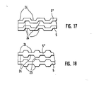
- FIG. 17 shows an embodiment in which the ribs 5, 5 'and 5 "are meandering or, in other words, in which the ribs are provided with transverse grooves that run perpendicular to their longitudinal direction and are offset on both sides on a gap
- the ribs 5, 5 1 and 5 are on both sides of the Provided ribs 24 in the same place or, if one assumes that the normal ribs correspond to the thinner intermediate web structure, they each have transverse ribs 25 arranged on both sides.
Landscapes
- Chemical & Material Sciences (AREA)
- Engineering & Computer Science (AREA)
- Organic Chemistry (AREA)
- Chemical Kinetics & Catalysis (AREA)
- Ceramic Engineering (AREA)
- Physics & Mathematics (AREA)
- Thermal Sciences (AREA)
- Mechanical Engineering (AREA)
- General Engineering & Computer Science (AREA)
- Catalysts (AREA)
Applications Claiming Priority (4)
| Application Number | Priority Date | Filing Date | Title |
|---|---|---|---|
| DE19853522095 DE3522095A1 (de) | 1985-06-20 | 1985-06-20 | Vorrichtung zum behandeln stroemender medien und verfahren zu ihrer herstellung |
| DE3522095 | 1985-06-20 | ||
| DE8521746U | 1985-07-27 | ||
| DE19858521746 DE8521746U1 (de) | 1985-07-27 | 1985-07-27 | Vorrichtung zum Behandeln strömender Medien |
Publications (1)
| Publication Number | Publication Date |
|---|---|
| EP0206067A1 true EP0206067A1 (fr) | 1986-12-30 |
Family
ID=25833290
Family Applications (1)
| Application Number | Title | Priority Date | Filing Date |
|---|---|---|---|
| EP86107810A Withdrawn EP0206067A1 (fr) | 1985-06-20 | 1986-06-07 | Structure active catalytiquement constituée d'éléments individuels et procédé pour la préparation de ces éléments |
Country Status (1)
| Country | Link |
|---|---|
| EP (1) | EP0206067A1 (fr) |
Cited By (5)
| Publication number | Priority date | Publication date | Assignee | Title |
|---|---|---|---|---|
| US4760047A (en) * | 1986-04-28 | 1988-07-26 | Didier-Werke Ag | Catalyst block |
| US5403184A (en) * | 1992-05-20 | 1995-04-04 | Matsushita Electric Industrial Co., Ltd. | Exothermic apparatus |
| EP0923980A1 (fr) * | 1997-12-17 | 1999-06-23 | Günter Horst | Catalyseur pour postcombustion catalytique des gaz d'échappement |
| EP0873491A4 (fr) * | 1995-12-29 | 2000-03-08 | Lantec Products Inc | Garnissage ceramique pourvu de canaux, pour lits thermiques et catalytiques |
| WO2003099429A1 (fr) * | 2002-05-21 | 2003-12-04 | Battelle Memorial Institute | Reacteurs a section transversale variable, procedes permettant de produire ceux-ci, et procede permettant de produire des reactions avec des temps de contact local variables |
Citations (5)
| Publication number | Priority date | Publication date | Assignee | Title |
|---|---|---|---|---|
| US3910850A (en) * | 1973-12-19 | 1975-10-07 | Grace W R & Co | Contoured monolithic substrate |
| DE2529358A1 (de) * | 1974-07-11 | 1976-01-29 | Advanced Materials Eng | Waermetauscher |
| US4028275A (en) * | 1973-01-24 | 1977-06-07 | Mitsui Mining & Smelting Co., Ltd. | Process for preparing catalytic materials for purifying exhaust gas and catalytic materials prepared thereby |
| DE2934973A1 (de) * | 1978-09-01 | 1980-03-13 | Gte Sylvania Inc | Keramische waermerekuperatorkonstruktion und -anordnung |
| EP0097726A1 (fr) * | 1982-06-24 | 1984-01-11 | Rockwell International Corporation | Echangeur de chaleur |
-
1986
- 1986-06-07 EP EP86107810A patent/EP0206067A1/fr not_active Withdrawn
Patent Citations (5)
| Publication number | Priority date | Publication date | Assignee | Title |
|---|---|---|---|---|
| US4028275A (en) * | 1973-01-24 | 1977-06-07 | Mitsui Mining & Smelting Co., Ltd. | Process for preparing catalytic materials for purifying exhaust gas and catalytic materials prepared thereby |
| US3910850A (en) * | 1973-12-19 | 1975-10-07 | Grace W R & Co | Contoured monolithic substrate |
| DE2529358A1 (de) * | 1974-07-11 | 1976-01-29 | Advanced Materials Eng | Waermetauscher |
| DE2934973A1 (de) * | 1978-09-01 | 1980-03-13 | Gte Sylvania Inc | Keramische waermerekuperatorkonstruktion und -anordnung |
| EP0097726A1 (fr) * | 1982-06-24 | 1984-01-11 | Rockwell International Corporation | Echangeur de chaleur |
Cited By (5)
| Publication number | Priority date | Publication date | Assignee | Title |
|---|---|---|---|---|
| US4760047A (en) * | 1986-04-28 | 1988-07-26 | Didier-Werke Ag | Catalyst block |
| US5403184A (en) * | 1992-05-20 | 1995-04-04 | Matsushita Electric Industrial Co., Ltd. | Exothermic apparatus |
| EP0873491A4 (fr) * | 1995-12-29 | 2000-03-08 | Lantec Products Inc | Garnissage ceramique pourvu de canaux, pour lits thermiques et catalytiques |
| EP0923980A1 (fr) * | 1997-12-17 | 1999-06-23 | Günter Horst | Catalyseur pour postcombustion catalytique des gaz d'échappement |
| WO2003099429A1 (fr) * | 2002-05-21 | 2003-12-04 | Battelle Memorial Institute | Reacteurs a section transversale variable, procedes permettant de produire ceux-ci, et procede permettant de produire des reactions avec des temps de contact local variables |
Similar Documents
| Publication | Publication Date | Title |
|---|---|---|
| DE3880386T2 (de) | Wirbelbettrockner mit einer bettplatte und benutzung einer solchen platte in einem wirbelbettrockner. | |
| EP0484364A1 (fr) | Corps en nid d'abeilles, a aretes internes d'entree, notamment support de catalyseur pour vehicule automobile. | |
| DE4116886A1 (de) | Ein gelochtes blech und ein verfahren zur herstellung desselben | |
| EP0809001A1 (fr) | Collecteur d'échappement | |
| EP0482145A1 (fr) | Dispositif melangeur, dispositif catalyseur et utilisation du dispositif catalyseur. | |
| EP0152560B1 (fr) | Matrice pour réacteur catalytique pour purifier des gaz d'échappement | |
| DE3744265C2 (de) | Rußfilter zur Abgasreinigung in Kraftfahrzeugen | |
| EP3436189B1 (fr) | Contacteur | |
| EP2129638B1 (fr) | Filtre à particules diesel pourvu d'un corps filtrant en céramique | |
| DE69835696T2 (de) | Katalysator zur abgasemissionskontrolle, katalysatorstruktur, verfahren zur herstellung derselben, verfahren und vorrichtung zur abgasemissionskontrolle | |
| WO1992002717A1 (fr) | Corps en nid d'abeilles ayant des canaux a sections transversales diverses, notamment corps de support de catalyseur | |
| EP0411421B1 (fr) | Procédé de production d'un filtre et filtre produit ainsi | |
| WO1988001722A1 (fr) | Echangeur de chaleur du type a plaques | |
| EP1848534B1 (fr) | Corps en nid d'abeilles a cavites internes | |
| EP0206067A1 (fr) | Structure active catalytiquement constituée d'éléments individuels et procédé pour la préparation de ces éléments | |
| EP1853800A1 (fr) | Corps alveolaire a faces fissurees | |
| EP0577117A2 (fr) | Procédé pour la fabrication d'un catalyseur | |
| DE2527787A1 (de) | Wabenfoermiges strangpressteil sowie strangpresskopf und verfahren zu seiner herstellung | |
| DE2315981C3 (de) | Vorrichtung zur Trocknung von in Etagen mit Abstand voneinander angeordneten Gipsplatten | |
| DE3522095A1 (de) | Vorrichtung zum behandeln stroemender medien und verfahren zu ihrer herstellung | |
| EP1753520A1 (fr) | Piece rapportee de nettoyage pour systemes de purification des gaz d'echappement, en particulier pour filtres a particules | |
| EP2099547A1 (fr) | Procédé de production d'un corps filtrant en céramique | |
| EP1449584A1 (fr) | Objet du type nid d'abeilles et son utilisation | |
| EP1961717B1 (fr) | Filtre à particules diesel doté d'un corps de filtre céramique | |
| EP0375986A1 (fr) | Support pour un réacteur catalytique pour la purification des gaz d'échappement |
Legal Events
| Date | Code | Title | Description |
|---|---|---|---|
| PUAI | Public reference made under article 153(3) epc to a published international application that has entered the european phase |
Free format text: ORIGINAL CODE: 0009012 |
|
| AK | Designated contracting states |
Kind code of ref document: A1 Designated state(s): AT DE FR GB IT |
|
| 17P | Request for examination filed |
Effective date: 19870526 |
|
| 17Q | First examination report despatched |
Effective date: 19880504 |
|
| STAA | Information on the status of an ep patent application or granted ep patent |
Free format text: STATUS: THE APPLICATION IS DEEMED TO BE WITHDRAWN |
|
| 18D | Application deemed to be withdrawn |
Effective date: 19890704 |
|
| RIN1 | Information on inventor provided before grant (corrected) |
Inventor name: WINKLER, HANS E. |