EP0206111A1 - Digitales lokales Vermittlungssystem - Google Patents
Digitales lokales Vermittlungssystem Download PDFInfo
- Publication number
- EP0206111A1 EP0206111A1 EP86107941A EP86107941A EP0206111A1 EP 0206111 A1 EP0206111 A1 EP 0206111A1 EP 86107941 A EP86107941 A EP 86107941A EP 86107941 A EP86107941 A EP 86107941A EP 0206111 A1 EP0206111 A1 EP 0206111A1
- Authority
- EP
- European Patent Office
- Prior art keywords
- calls
- packet
- switching
- channels
- digital
- Prior art date
- Legal status (The legal status is an assumption and is not a legal conclusion. Google has not performed a legal analysis and makes no representation as to the accuracy of the status listed.)
- Granted
Links
- 230000005540 biological transmission Effects 0.000 claims abstract description 13
- 230000011664 signaling Effects 0.000 claims abstract description 8
- 238000000034 method Methods 0.000 claims description 12
- 238000012545 processing Methods 0.000 claims description 7
- 230000008569 process Effects 0.000 claims description 3
- 230000006870 function Effects 0.000 description 9
- 238000004891 communication Methods 0.000 description 4
- 238000010586 diagram Methods 0.000 description 4
- 238000012423 maintenance Methods 0.000 description 2
- 238000012544 monitoring process Methods 0.000 description 2
- 238000012546 transfer Methods 0.000 description 2
- 101000864098 Homo sapiens Small muscular protein Proteins 0.000 description 1
- 102100029873 Small muscular protein Human genes 0.000 description 1
- 230000004913 activation Effects 0.000 description 1
- 230000008859 change Effects 0.000 description 1
- 239000012141 concentrate Substances 0.000 description 1
- 238000012217 deletion Methods 0.000 description 1
- 230000037430 deletion Effects 0.000 description 1
- 238000001514 detection method Methods 0.000 description 1
- 238000003780 insertion Methods 0.000 description 1
- 230000037431 insertion Effects 0.000 description 1
- 238000012986 modification Methods 0.000 description 1
- 230000004048 modification Effects 0.000 description 1
- 230000001629 suppression Effects 0.000 description 1
- 239000000725 suspension Substances 0.000 description 1
Images

Classifications
-
- H—ELECTRICITY
- H04—ELECTRIC COMMUNICATION TECHNIQUE
- H04Q—SELECTING
- H04Q11/00—Selecting arrangements for multiplex systems
- H04Q11/04—Selecting arrangements for multiplex systems for time-division multiplexing
- H04Q11/0428—Integrated services digital network, i.e. systems for transmission of different types of digitised signals, e.g. speech, data, telecentral, television signals
-
- H—ELECTRICITY
- H04—ELECTRIC COMMUNICATION TECHNIQUE
- H04M—TELEPHONIC COMMUNICATION
- H04M11/00—Telephonic communication systems specially adapted for combination with other electrical systems
- H04M11/06—Simultaneous speech and data transmission, e.g. telegraphic transmission over the same conductors
- H04M11/068—Simultaneous speech and data transmission, e.g. telegraphic transmission over the same conductors using time division multiplex techniques
Definitions
- This invention relates to a digital local switching system for switching voice and data signals comprising circut switching calls , packet switching calls, and digitized signalling information.
- ISDN Integrated Service Digital Network
- I. Series recommendation on the basic specifications toward the end of 1984.
- ISDN's user network interface which determines the boundary conditions for effectively connecting users' terminals with the network for optimal communication is constructed with two B channels of 64 kilobits per second (Kbps) and one D channel of 16 Kbps (2B + D).
- This interface is referred to as the basic access interface which enables, for example, communication through a speech channel (Bl) of 64 Kbps, a data channel (B2) of 64 Kbps, and a data channel (D) for low speed packets of 16 Kbps.
- the ISDN's user network interface allows each call to select various different services for use.
- Demands for service to the network or demands for a call are expressed in a message called SETUP.
- the SETUP messages are packetized and transferred through D channel from a user to the network.
- the SETUP message is written with (1) a call reference value for identifying the call, (2) bearer capability for designating the transfer rate and mode of connection needed by the particular call, (3) channel identification for identifying which of the two B channels or D channel should be used, and (4) an ISDN destination address of the other party for designating the telephone number thereof.
- the function to deal with the call controlling procedures with such messages is called layer-3 which is referred to in I.450 and I.451 of the above-mentioned CCITT Recommendation I.
- the procedure for correctly transferring the messages of the layer-3 is called layer-2 which is mentioned under the title; Link Access Procedure on the D channel (LAP-D) in I.440 and I.441 of the CCITT Recommendation.
- LAP-D has functions such as connecting/disconnecting to and from a data link, identifying frames, sequence control, error detection, error restoration, flow control, etc.
- SAPI service access point identifier
- Sections I.430 and I.431 of the CCITT Recommendation specifies channel structure, conditions for activation and suspension, speed, electric voltage level, number and forms of connector pins, etc. of layer 1.
- the switching system In an ISDN, various different services should be received through a common subscriber interface. Firstly, the switching system, therefore, should accommodate the user network interface specified by the CCITT Recommendation. Secondly, the switching system should connect calls of various types which are incoming from and outgoing to the ISDN subscribers, for instance, calls having both attributes of a circuit switching call and a packet switching call. The packet calls are classified into two types in ISDN; i.e., those transferred via D channel, and those transferred via B channel. Thirdly, the ISDN switching system should handle both of them.
- a prior local switching system should be either replaced with a digital telephone exchange with means for processing packet-switched data in addition to circuit switched data like the one disclosed in U.S. Patent No. 4,486,878, or provided separately with a switching system dedicated exclusively for packet switching either at local switch or toll switch so that circuit switching calls are controlled to be connected to a circuit switching system and packet switching calls are controlled to be connected to a packet switching system separately.
- the former method is simpler in the structure of networks and most preferable in service when viewed from ISDN subscriber side.
- the method may therefore be the most popular solution when ISDN prevails widely in future. But then, all of the prior switching systems should be invalidated for ISDN subscribers. Immediate application of the former method may not be very economical.
- the switching section of a prior digital switching system can be still used as the switching section for circuit switching calls.
- the latter method seems to be more feasible a method at least for the initial stage in the ISDN introduction process.
- the location be decided depending on the ratio in traffic between packet switching calls and circuit switching calls; more specifically, if the traffic ratio is high in the packet.switching calls, it-should be installed at a local switch while if it is high in the circuit switching calls, it should be installed at a toll switch.
- the traffic of packet calls is much smaller than that of circuit switching calls, and it is considered economically more practical that the packet switching system is installed at a toll switch and subscribers should have access to it whenever necessary.
- the toll connecting trunk can be shared in use by circuit switching calls and packet switching calls, and that the ratio in the number between channels used by packet switching calls and those used by circuit switching calls on the toll connecting trunk should be variable or, in other words, should be a variable boundary in structure.
- the ratio may be semi-variable, but is preferred to be dynamically variable to achieve higher effect.
- the existing systems cannot meet such requirements.
- An object of this invention is to provide a digital switching system which is capable of connecting various services of circuit switching as well as packet switching on one single local digital line while minimizing the influence on the local switching system and which is capable of introducing ISDN with higher economical effect while minimizing the influence on the network in the initial stage thereof.
- Another object of this invention is to provide a digital switching system which can minimize the necessity of changes in a local switching system which otherwise is entailed by accommodating ISDN subscribers, or in other words, which can connect ISDN subscribers by using the switching section of the existing telephone digital local switching system without modifications and adding an ISDN subscriber interface.
- Still another object of this invention is to provide a digital switching system which is so structured that a toll connecting trunk (TCT) can be shared commonly by circuit switching calls and packet switching calls and thus to secure higher effective use of the trunk.
- TCT toll connecting trunk
- Yet another object of this invention is to provide a digital switching system which is structured to connect packet switching calls incoming from or outgoing to ISDN subscribers to a packet switching system without passing them through a circuit switching system to thereby effectively use the speech pathes of the circuit switching section instead of using it for packet switching calls and at the same time, to minimize the influence of the ISDN introduction on the software of the circuit switching section.
- the ISDN digital switching network to which this invention is applicable is assumed that circuit switching calls are to be switched at a local switch and packet switching calls are to be switched at a toll switch.
- a digital switching system which comprising:
- the digital switching network to which this invention is applicable includes local switches (LS's) 10, 30 and a toll switch (TS) 20.
- the LS 10, the TS 20, and digital terminals connected to the LS 10 is taken as an example.
- Digital terminals such as a data terminal (DT) 51 and a telephone terminal (TT) 52 are connected to a network terminal (NT) 41.
- digital terminals such as a video terminal (VT) 53 and a telephone terminal (TT) 54 are connected to a newtork terminal (NT) 42.
- the above combination of the digital terminals is a mere example.
- the NT's 41 and 42 are connected to a line module (LM) 11 in.
- LM line module
- the LM 11 is connected -to a time division switch (TDSW) 12 for circuit switching and a system packet multiplexer (SPMX) 13.
- TDSW time division switch
- SPMX system packet multiplexer
- Voice signals, data signals and signalling information given from the DT 51, TT's 52 and 54, and the VT 53 via the NT's 41 and 42 are separated within the LM 11 into the circuit switching calls transferred through B channels, the B channel packet calls transferred through B channel and the D channel packet calls transferred through D channel.
- the circuit switching calls are connected to the TDSW 12 while the B channel packet calls and D channel packet calls are connected to the SPMX 13 respectively.
- the toll connecting trunks (TCT) 61 and 62 are general digital lines and have bit rates of, for instance, 2.048 megabits per second (Mbps) (primary group), 8.448 Mbps (secondary group) [in North America, 1.544 Mbps (primary group) and 6.312 Mbps (secondary group)].
- the TCT 61 is connected to digital cross-connect modules (DXM's) 14 and 21 in switches LS 10 and TS 20.
- D X M's 14, 21 and 24 are line interface units for respective switches.
- DXM 14 in the LS 10 is connected to the TDSW 12 and the SPMX 13 and has the function to insert/drop separately the packet calls which have been concentrated and multiplexed at the SPMX 13 together with circuit switching calls communicated via the TDSW 12 in channels of the TCT 61 which have been designated in advance.
- the DXM of the LS 30 has the similar function to insert/drop separately the packet calls and circuit switching calls in the channels in the TCT 62 designated in advance. Any channel may be designated arbitrarily out of those on the digital circuit, but once designated, the channel should be used in a semi- fixed manner until the designation is changed.
- the ratio of the channels in number used for packet switching calls against the circuit switching calls depends on the traffic of the time and decided by the negotiation between the LS 10 and the TS 20.
- circuit switching calls and packet switching calls are separated depending on the channels of the digital line designated by DXM's 21 and 24 so that circuit switching calls are to be processed by a time division switch (TDSW) 21 for a circuit switching call while packet switching calls are to be processed by a packet switch (PS) 23.
- TDSW time division switch
- PS packet switch
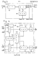
- an embodiment of this invention local switching system (LS) 10 shown in FIG. 1 provides a plurality of line modules (LM) 11 0 through lln.
- Each LM has digital line circuits (DLC) 211 and 212.
- DLC's 211 and 212 are connected at the interfaces which are called U interfaces to digital access lines 71 and 72 within the ISDN local interface.
- DLC's 211 and 212 have the terminating functions of layer 1 (physical layer) and layer 2 (data link layer). More specifically, DLC's 211 and 212 conduct electric terminating for the U interface, terminating for the layer 1 such as synchronization and terminating for the LAP-D.
- DLC's 211 and 212 comprise respectively a line terminator (LT) 311, a D channel handler (DCH) 312 and a dropper/inserter (DI) 313.
- the LT 311 terminates the layer 1 of a U interface.
- the DCH 312 terminates the LAP-D.
- the DI 313 has the function to separately insert/drop Bl, B2 and D channels from the format of the ISDN basic interface of (2B + D) and to branch out to the digital line switch (DLSW) 213 when Bl and B2 are circuit switching calls and to the line module packet multiplexer (LMPX) 215 when Bl and B2 are packet switching calls.
- DLSW digital line switch
- LMPX line module packet multiplexer
- the line module controller (LMC) 214 controls to connect Bl and B2 to either the DLSW 213 or the LMPMX 215 respectively. More specifically, a signalling information from a digital terminal is conveyed through D channel to either the DLC 211 or the DLC 212. The signalling information includes the information to indicate whether the originating call is a packet switching call or a circuit switching call. With such information, the LMC 214 controls to connect Bl and B2 to either the DLSW 213 or the LMPMX 215.
- the outputs from DLC's 211 and 212, two B channels (Bl and B2) which are circuit switching calls are respectively connected to the DLSW 213. They may be connected by separate highway or multiplexed on single highway.
- the DLSW 213 concentrates and multiplexes B channels from DLC's 211 and 212 and connect the same to the TDSW 12.
- the TDSW 12 further multiplexes circuit switching calls which have been concentrated by plural LM's 11 0 through ll n to the degree identical to the multiplexity of the main highway and connects speech lines to line module or trunk module of a relevant opposite party via . switch network whenever necessary.
- flag synchronization, zero insertion/ deletion, control of errors caused by re-transfer and other processing on layer 2 are conducted with subscriber's terminal to which they are connected and conveys either circuit signal information or D channel packet to the LMC 214.
- the LMC 214 receives D channel packets from DLC's 211 and 212, and checkes SAPI in the D channel packets. If the SAPI is 0, the LMC 214 processes the circuit signal data for necessary call processing. Along with the processing, necessary control within the system such as communication between the control data 216 of the DLSW 213 and the control data 217 of a switch control section (CTL) 250 or the controlling section of the TDSW 12 is connected.
- CTL switch control section
- the LMPMX 215 multiplexes D channel packets from the LMC 214 and B channel packets from DLC's 211 and 212, to feed them to the SPMX 13.
- the packets which use B channel are added with physical address corresponding to the position of connection of subscribers in a manner similar to D channel packets.
- the packets received from the SPMX 13 are distributed to appropriate LM's depending on the physical address data included therein.
- the SPMX 13 are installed in the unit of plural line modules (LM) 11 0 through ll n , and on the up-link side thereof (the direction from LS toward TS is called up-link and the reverse direction down-link herein), packets received from each line module are added with address data identifying line modules to which or from which the packet comes or goes, further multiplexed and sent out to a digital cross-connect module (DXM) 14.
- DXM digital cross-connect module
- On the side of down-link which line modules LM should be allocated to the module is determined by referring to said address data and the packet is sent out to a relevant module.
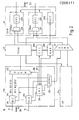
- the DXM 14 comprises circuit packet multiplexers (CPMX) 221 and 231 for multiplexing circuit switching calls from the TDSW 12 and packet switching calls from the SMPX 13, digital transmission interfaces (DTI) 222 and 231, and a digital cross-connect controller the DXCC 240 for controlling the combination of these plural CPMX's 221 and 231 with DTI's 222 and 232.
- CPMX circuit packet multiplexers
- DTI digital transmission interfaces
- the DXM comprises the CPMX 221, the DTI 222 and the DXCC 240.
- the CPMX 221 provides a selector (SEL) 411 on the up-link side for selecting pathes from the TDSW 12 and from the SPMX 13 in the unit of time slots.
- the CPMX 221 provides the DEC 413 on the down-link side for separating predetermined time slots of circuit switching calls and adding the remaining time slots with idle channel patterns to send them to the TDSW 12. It also removes circuit switching calls from the packet switching calls to send them to the SPMX 13.
- the CPMX 221 is a variable multiplexer and is controlled by an inserter/dropper control memory (IDCM) 412 in time slots.
- IDCM inserter/dropper control memory
- the IDCM 412 is written in and read out with the data of the memory from the DXCC 240 which is a controlling circuit for the whole the DXM 14.
- the content of the IDCM 412 is controlled by a maintenance controller (MNC) 260 to be re-written via the DXCC 240 to thereby change the band width which circuit switching calls and packet switching calls use.
- MNC maintenance controller
- a digital transmission interface (DTI) 222 has the functions for interfacing the TCT 61 such as bit synchronization, frame synchronization, frame aligment, fault monitoring on digital transmission lines, etc.
- a transmission interface receiving block (SND) 431 has the functions of inserting a frame pattern, zero suppression, sending out alarm signals to the opposite station, etc.
- a unipolar/bipolar converter (UB) 432 converts the unipolar signals within the switching system into bipolar signals on the digital transmission line.
- the bipolar signals on the digital transmission line from the toll switch are converted into unipolar signals within the switching system and sent to a transmission interface receiving block (RCV) 434.
- the RCV 434 conducts such processing as bit synchronization, frame synchronization and frame alignment processing for aligning the frame phase of digital transmission line to the phase of the switching system.
- the RCV 434 has the function to monitor faults on the digital transmission lines and, if it finds a fault, to report the fault to the DXCC 240. The DXCC 240 then reports the fault to the MNC 260.
- the MNC 260 is a device for monitoring faults and for controlling devices for maintenance within the switching system. In order to achieve such tasks, the MNC 260 receives and transmits from and to LMC's 214 and 250 the data necessary for operation of the system.
Landscapes
- Engineering & Computer Science (AREA)
- Computer Networks & Wireless Communication (AREA)
- Signal Processing (AREA)
- Data Exchanges In Wide-Area Networks (AREA)
Applications Claiming Priority (6)
| Application Number | Priority Date | Filing Date | Title |
|---|---|---|---|
| JP12626485 | 1985-06-12 | ||
| JP12626585 | 1985-06-12 | ||
| JP126263/85 | 1985-06-12 | ||
| JP12626385 | 1985-06-12 | ||
| JP126264/85 | 1985-06-12 | ||
| JP126265/85 | 1985-06-12 |
Publications (2)
| Publication Number | Publication Date |
|---|---|
| EP0206111A1 true EP0206111A1 (de) | 1986-12-30 |
| EP0206111B1 EP0206111B1 (de) | 1990-08-29 |
Family
ID=27315295
Family Applications (1)
| Application Number | Title | Priority Date | Filing Date |
|---|---|---|---|
| EP86107941A Expired EP0206111B1 (de) | 1985-06-12 | 1986-06-11 | Digitales lokales Vermittlungssystem |
Country Status (4)
| Country | Link |
|---|---|
| US (1) | US4731782A (de) |
| EP (1) | EP0206111B1 (de) |
| CA (1) | CA1253940A (de) |
| DE (1) | DE3673700D1 (de) |
Cited By (2)
| Publication number | Priority date | Publication date | Assignee | Title |
|---|---|---|---|---|
| US4933931A (en) * | 1988-06-17 | 1990-06-12 | Fujitsu Limited | Integrated accounting system |
| EP0643522A1 (de) * | 1993-09-14 | 1995-03-15 | AT&T Corp. | Informationsdienstsystem für Telephone mit digitaler und ausser Band fallender Signalgebung |
Families Citing this family (10)
| Publication number | Priority date | Publication date | Assignee | Title |
|---|---|---|---|---|
| US4910729A (en) * | 1988-05-10 | 1990-03-20 | Harris Corporation | ISDN traffic generator adapter |
| US5134611A (en) * | 1988-09-30 | 1992-07-28 | Microcom, Inc. | Analog/digital data device and method |
| US4996685A (en) * | 1989-04-10 | 1991-02-26 | Bell Communications Research, Inc. | Technique for dynamically changing an ISDN connection during a host session |
| US5268903A (en) * | 1991-10-02 | 1993-12-07 | Rockwell International Corporation | Multichannel telephonic switching network with different signaling formats and cross connect/PBX treatment selectable for each channel |
| JP2596346B2 (ja) * | 1993-11-29 | 1997-04-02 | 日本電気株式会社 | Lan間接続装置 |
| US5577042A (en) * | 1994-01-18 | 1996-11-19 | Mcgraw Broadcast | Broadcast and presentation system and method |
| JPH09271085A (ja) * | 1996-04-03 | 1997-10-14 | Fujitsu Ltd | データリンク処理装置及び加入者系端局装置 |
| JP4198356B2 (ja) * | 1999-08-30 | 2008-12-17 | 富士通株式会社 | Isdnアラーム通知システム |
| US8718087B1 (en) * | 2006-10-24 | 2014-05-06 | Marvell International Ltd. | Processing architecture for passive optical network |
| US9178713B1 (en) | 2006-11-28 | 2015-11-03 | Marvell International Ltd. | Optical line termination in a passive optical network |
Citations (3)
| Publication number | Priority date | Publication date | Assignee | Title |
|---|---|---|---|---|
| EP0105212A2 (de) * | 1982-09-07 | 1984-04-11 | Siemens Aktiengesellschaft | Schaltungsanordnung zum Übertragen von Signalen zwischen Teilnehmeranschlussleitungen und wenigstens einer Übertragungsleitung einer dienstintegrierten Fernmeldeanlage |
| GB2132446A (en) * | 1982-12-01 | 1984-07-04 | Standard Telephones Cables Ltd | Telecommunication exchange system |
| EP0147865A2 (de) * | 1983-12-29 | 1985-07-10 | Fujitsu Limited | Digitales Vermittlungssystem |
Family Cites Families (1)
| Publication number | Priority date | Publication date | Assignee | Title |
|---|---|---|---|---|
| FR2475827B1 (fr) * | 1980-02-13 | 1987-05-29 | Dauphin Jean Louis | Systeme de commutation numerique a division du temps pour voies mic vehiculant la parole et des donnees en mode-paquet |
-
1986
- 1986-06-11 DE DE8686107941T patent/DE3673700D1/de not_active Expired - Lifetime
- 1986-06-11 EP EP86107941A patent/EP0206111B1/de not_active Expired
- 1986-06-11 CA CA000511292A patent/CA1253940A/en not_active Expired
- 1986-06-11 US US06/872,810 patent/US4731782A/en not_active Expired - Lifetime
Patent Citations (3)
| Publication number | Priority date | Publication date | Assignee | Title |
|---|---|---|---|---|
| EP0105212A2 (de) * | 1982-09-07 | 1984-04-11 | Siemens Aktiengesellschaft | Schaltungsanordnung zum Übertragen von Signalen zwischen Teilnehmeranschlussleitungen und wenigstens einer Übertragungsleitung einer dienstintegrierten Fernmeldeanlage |
| GB2132446A (en) * | 1982-12-01 | 1984-07-04 | Standard Telephones Cables Ltd | Telecommunication exchange system |
| EP0147865A2 (de) * | 1983-12-29 | 1985-07-10 | Fujitsu Limited | Digitales Vermittlungssystem |
Non-Patent Citations (6)
| Title |
|---|
| ERICSSON REVIEW, vol. 61, May 1984, pages 20-27, ISDN, Stockholm, SE; O. BORGSTRÖM et al.: "AXE 10 for ISDN" * |
| IEEE COMMUNICATIONS MAGAZINE, vol. 22, no. 2, February 1984, pages 16-26, IEEE, New York, US; M. GERLA et al.: "Bandwidth allocation and routing in ISDN's" * |
| INTERNATIONAL CONFERENCE ON THE ISDN AND ITS IMPACT ON INFORMATION TECHNOLOGY, 14th-16th January 1985, pages 41-46, IEE, London, GB; E. CANCER et al.: "The ISDN in Italy: Background, experiments, plans" * |
| PROCEEDINGS OF THE FOURTH INTERNATIONAL CONFERENCE ON COMPUTER COMMUNICATION, EVOLUTIONS IN COMPUTER COMMUNICATIONS, Kyoto, JP, 26th-29th September 1978, pages 557-563, North-Holland Publishing Co., Amsterdam, NL; R. PARODI et al.: "Evaluation of different data communication media within an integrated telecommunication system" * |
| PROCEEDINGS OF THE INTERNATIONAL SWITCHING SYMPOSIUM, Florence, IT, 7th-11th May 1984, Session 21B, pages 1-6, North-Holland, Amsterdam, NL; G. RIBBECK et al.: "EWSD as a basis for ISDN" * |
| PROCEEDINGS OF THE INTERNATIONAL SWITCHING SYMPOSIUM, Florence, IT, 7th-11th May 1984, Session 22B, pages 1-6, North-Holland, Amsterdam, NL; R. DAVID et al.: "Data feature implementation and ISDN-trial in the Belgian network" * |
Cited By (2)
| Publication number | Priority date | Publication date | Assignee | Title |
|---|---|---|---|---|
| US4933931A (en) * | 1988-06-17 | 1990-06-12 | Fujitsu Limited | Integrated accounting system |
| EP0643522A1 (de) * | 1993-09-14 | 1995-03-15 | AT&T Corp. | Informationsdienstsystem für Telephone mit digitaler und ausser Band fallender Signalgebung |
Also Published As
| Publication number | Publication date |
|---|---|
| US4731782A (en) | 1988-03-15 |
| DE3673700D1 (de) | 1990-10-04 |
| CA1253940A (en) | 1989-05-09 |
| EP0206111B1 (de) | 1990-08-29 |
Similar Documents
| Publication | Publication Date | Title |
|---|---|---|
| US4413337A (en) | Time division switching system for circuit mode and packet mode lines | |
| US4707826A (en) | Circuit and packet data transmission system | |
| CA2326894A1 (en) | Voice and data apparatus comprising a selective tapping digital signal processing resource | |
| US4731782A (en) | Digital local switching system for integrated service digital network | |
| CA2175853C (en) | Method and apparatus for interfacing low speed access links to a high speed time multiplexed switch fabric | |
| US5181199A (en) | Packet switching system | |
| CA1337081C (en) | Automatic telecommunications systems | |
| JPH11331191A (ja) | 加入者アクセス装置 | |
| EP0983693B1 (de) | Nachrichtenverkehrsteuerung | |
| US5590129A (en) | Single stage telecommunications switch with partitioned processors | |
| US5398246A (en) | ISDN private local switching system | |
| EP0230676A2 (de) | Integrierte Vermittlung | |
| JPH0638616B2 (ja) | Isdn加入者用デジタル交換機 | |
| JP2710559B2 (ja) | 伝送路バックアップ機能付の多重化装置 | |
| JPH0638617B2 (ja) | 高速回線交換端末を収容するデジタル交換機 | |
| JP3151768B2 (ja) | 同期・非同期転送モード対応型セルフヒーリング・リング方式 | |
| CN1078790C (zh) | 带内线路信号数字中继线 | |
| JP3129196B2 (ja) | Dチャネルパケット集線方式 | |
| CA2286803A1 (en) | Method for subscriber information transfer in a local line distribution network | |
| JPH0595335A (ja) | 時分割多重通信システム | |
| JP2828417B2 (ja) | 電話交換機におけるアナログ回線関連情報信号とisdn回線関連情報信号との統一スイッチング方式 | |
| US7366198B2 (en) | Method and system for packet and circuit telephony in a distributed telecommunications switching system | |
| AU641828B2 (en) | A method of transmitting data on a telecommunications network | |
| KR100209812B1 (ko) | 종합 정보 통신망(isdn)에서의 지연등화 프로토콜을 위한 채널 추가 요구 프리미티브 처리 방법 | |
| JP3035967B2 (ja) | 遠隔加入者収容装置 |
Legal Events
| Date | Code | Title | Description |
|---|---|---|---|
| PUAI | Public reference made under article 153(3) epc to a published international application that has entered the european phase |
Free format text: ORIGINAL CODE: 0009012 |
|
| 17P | Request for examination filed |
Effective date: 19860611 |
|
| AK | Designated contracting states |
Kind code of ref document: A1 Designated state(s): DE FR NL |
|
| 17Q | First examination report despatched |
Effective date: 19880714 |
|
| GRAA | (expected) grant |
Free format text: ORIGINAL CODE: 0009210 |
|
| AK | Designated contracting states |
Kind code of ref document: B1 Designated state(s): DE FR NL |
|
| REF | Corresponds to: |
Ref document number: 3673700 Country of ref document: DE Date of ref document: 19901004 |
|
| ET | Fr: translation filed | ||
| PLBE | No opposition filed within time limit |
Free format text: ORIGINAL CODE: 0009261 |
|
| STAA | Information on the status of an ep patent application or granted ep patent |
Free format text: STATUS: NO OPPOSITION FILED WITHIN TIME LIMIT |
|
| 26N | No opposition filed | ||
| PGFP | Annual fee paid to national office [announced via postgrant information from national office to epo] |
Ref country code: NL Payment date: 20050605 Year of fee payment: 20 |
|
| PGFP | Annual fee paid to national office [announced via postgrant information from national office to epo] |
Ref country code: FR Payment date: 20050608 Year of fee payment: 20 |
|
| PGFP | Annual fee paid to national office [announced via postgrant information from national office to epo] |
Ref country code: DE Payment date: 20050609 Year of fee payment: 20 |
|
| PG25 | Lapsed in a contracting state [announced via postgrant information from national office to epo] |
Ref country code: NL Free format text: LAPSE BECAUSE OF EXPIRATION OF PROTECTION Effective date: 20060611 |
|
| NLV7 | Nl: ceased due to reaching the maximum lifetime of a patent |
Effective date: 20060611 |