EP0206204A1 - Séparateur pour fluide gazeux - Google Patents
Séparateur pour fluide gazeux Download PDFInfo
- Publication number
- EP0206204A1 EP0206204A1 EP86108199A EP86108199A EP0206204A1 EP 0206204 A1 EP0206204 A1 EP 0206204A1 EP 86108199 A EP86108199 A EP 86108199A EP 86108199 A EP86108199 A EP 86108199A EP 0206204 A1 EP0206204 A1 EP 0206204A1
- Authority
- EP
- European Patent Office
- Prior art keywords
- profile parts
- profile
- separator
- fluids
- sections
- Prior art date
- Legal status (The legal status is an assumption and is not a legal conclusion. Google has not performed a legal analysis and makes no representation as to the accuracy of the status listed.)
- Granted
Links
Images




Classifications
-
- B—PERFORMING OPERATIONS; TRANSPORTING
- B01—PHYSICAL OR CHEMICAL PROCESSES OR APPARATUS IN GENERAL
- B01D—SEPARATION
- B01D45/00—Separating dispersed particles from gases or vapours by gravity, inertia, or centrifugal forces
- B01D45/04—Separating dispersed particles from gases or vapours by gravity, inertia, or centrifugal forces by utilising inertia
- B01D45/06—Separating dispersed particles from gases or vapours by gravity, inertia, or centrifugal forces by utilising inertia by reversal of direction of flow
-
- B—PERFORMING OPERATIONS; TRANSPORTING
- B01—PHYSICAL OR CHEMICAL PROCESSES OR APPARATUS IN GENERAL
- B01D—SEPARATION
- B01D45/00—Separating dispersed particles from gases or vapours by gravity, inertia, or centrifugal forces
- B01D45/04—Separating dispersed particles from gases or vapours by gravity, inertia, or centrifugal forces by utilising inertia
- B01D45/08—Separating dispersed particles from gases or vapours by gravity, inertia, or centrifugal forces by utilising inertia by impingement against baffle separators
-
- F—MECHANICAL ENGINEERING; LIGHTING; HEATING; WEAPONS; BLASTING
- F24—HEATING; RANGES; VENTILATING
- F24C—DOMESTIC STOVES OR RANGES ; DETAILS OF DOMESTIC STOVES OR RANGES, OF GENERAL APPLICATION
- F24C15/00—Details
- F24C15/20—Removing cooking fumes
- F24C15/2035—Arrangement or mounting of filters
-
- Y—GENERAL TAGGING OF NEW TECHNOLOGICAL DEVELOPMENTS; GENERAL TAGGING OF CROSS-SECTIONAL TECHNOLOGIES SPANNING OVER SEVERAL SECTIONS OF THE IPC; TECHNICAL SUBJECTS COVERED BY FORMER USPC CROSS-REFERENCE ART COLLECTIONS [XRACs] AND DIGESTS
- Y10—TECHNICAL SUBJECTS COVERED BY FORMER USPC
- Y10T—TECHNICAL SUBJECTS COVERED BY FORMER US CLASSIFICATION
- Y10T24/00—Buckles, buttons, clasps, etc.
- Y10T24/44—Clasp, clip, support-clamp, or required component thereof
- Y10T24/44641—Clasp, clip, support-clamp, or required component thereof having gripping member formed from, biased by, or mounted on resilient member
- Y10T24/44769—Opposed engaging faces on gripping member formed from single piece of resilient material
-
- Y—GENERAL TAGGING OF NEW TECHNOLOGICAL DEVELOPMENTS; GENERAL TAGGING OF CROSS-SECTIONAL TECHNOLOGIES SPANNING OVER SEVERAL SECTIONS OF THE IPC; TECHNICAL SUBJECTS COVERED BY FORMER USPC CROSS-REFERENCE ART COLLECTIONS [XRACs] AND DIGESTS
- Y10—TECHNICAL SUBJECTS COVERED BY FORMER USPC
- Y10T—TECHNICAL SUBJECTS COVERED BY FORMER US CLASSIFICATION
- Y10T24/00—Buckles, buttons, clasps, etc.
- Y10T24/44—Clasp, clip, support-clamp, or required component thereof
- Y10T24/44641—Clasp, clip, support-clamp, or required component thereof having gripping member formed from, biased by, or mounted on resilient member
- Y10T24/44769—Opposed engaging faces on gripping member formed from single piece of resilient material
- Y10T24/44923—Clasp, clip, or support-clamp cut or shaped from a single sheet of resilient, uniformly thick, planar material
Definitions
- the invention relates to a separator for gaseous fluids such as cooling fluids, oil mist, grease mist, dirt-containing air with at least two opposite rows of channel-shaped first and second profile parts which are open in cross section, the free longitudinal edges of the edges of the first profile parts being the free longitudinal edges of the The edges of the second profile parts overlap.
- gaseous fluids such as cooling fluids, oil mist, grease mist, dirt-containing air
- a corresponding separator can be found in DE-PS 26 41 765 or DE-AS 27 18 611.
- the individual profile parts also known as gutters, are permanently installed in a frame.
- the entire separator In order to remove dirt separated between the profile parts, the entire separator must be removed and cleaned, for example from a suspended ceiling or from a housing accommodating several separator plates.
- CH-PS 550 018 a separator is described in which the edges of the facing channel-like profile parts overlap without forming chambers influencing the flow velocity of the fluids between them.
- the profile parts of each row are held by a frame that can be removed separately from the other. This simplifies cleaning to a certain extent. Nevertheless, especially with large-area separators, there is still an unwieldiness that is undesirable.
- the object of the present invention is, on the one hand, to design a separator of the type mentioned at the outset in such a way that increased separation is possible.
- the invention is also based on the object that the separator, that is to say the profile parts, can be cleaned without problems, and that separators of different surfaces can be produced without complex measures.
- the profile part for forming chambers has a projection extending in the apex region of the inner surface in the direction of the profile part opening and along its longitudinal axis.
- the presence of the projection which is to be referred to as the inner projection and protrudes from the apex region of the inner surface, preferably in the form of a drop or knob, provides additional chambers in the region of a profile part or to the edges of adjacent profile parts engaging in the profile part, thereby further influencing the The flow rate of the fluids flowing through the separator takes place, which in turn unexpectedly increases the degree of separation.
- each profile part is designed such that the edges of the profile parts arranged in the rows reach behind each other in such a way that a chamber influencing the flow velocity of the fluids forms between the narrowing of the edges, two further chambers are formed by the projection, through which the fluids experience a calming or acceleration when flowing through, so that a multi-stage cyclone system results.
- the outer surfaces of the projections are profiled at least in sections by z. B. projections, recesses or angles to each other describing surface sections, whereby an additional swirl takes place. This also causes the surfaces of the protrusions to self-clean.
- This structuring is preferably provided in the region of the front free end of the projections.
- each profile part can also have a structuring, at least in sections, in order to likewise ensure additional swirling and thus increased separation.
- This profiling can also be formed by projections, recesses, wave structure or surface sections describing angles to one another.
- each profile part is detachably arranged in the separator.
- the detachability of the profile part makes it easy to remove and, for example, clean and renew.
- the individual profile parts only need to be cut to the desired extent in order, for. B. to be used in an existing frame. Due to the detachable arrangement of the individual profile parts in the separator itself, there is also the possibility that the profile parts can be rotated about their longitudinal axes, which in turn allows the chambers influencing the flow velocity to be adjusted. As a result, focal separation can take place in desired areas of the separator.
- the profile parts themselves can be arcuate, V-shaped or U-shaped in section.
- an arc shape extending over more than 180 ° should be emphasized, so that the edges engage behind to form further chambers.
- the invention is characterized in that the projection and / or the profile parts can be made hollow, or in that the profile part can be cooled by tubular elements which can be fixedly or releasably connected to the profile part, one of which forms the projection.
- Media of adjustable temperature can flow through the tube elements. Water or a gas such as steam or cooling air can be used as the medium.
- holding elements are provided which are designed in such a way that they partially and at least partially surround the outer surface of the profile parts facing the fluids. With The profile parts facing the gases to be cleaned are fastened by partially enclosing the inner projection. At least the areas of the holding element that accommodate the profile parts are elastic.
- the holding elements themselves can be received, for example, by metal rails, which in turn have sections that cover the end regions of the profile parts.
- the rails receiving the holding elements can be designed in such a way that they can be adjusted in the same direction to the desired extent, so that the separator surfaces can consequently be adjusted with respect to the fluids that pass through.
- a construction is possible in which the rails receiving the holding elements are arranged such that the separator comprises two separating surfaces enclosing an acute angle, the inclination angles of which can be adjusted.
- the holding elements can be made of rubber, plastic or metal, for example, and can be formed in a type of bar that has the necessary recesses for interacting with the profile parts.
- the holder for the profile parts consists of individual elements which can be lined up, each of which comprises strip-shaped first and second sections starting from a base element and angled toward it and having spring properties, the first sections comprising the profile parts of the rising fluids facing the openings partially enclose the outside and the second portions with their end areas accommodate the inner projections of the profile parts facing the rising fluids with their outer surfaces for their fastening.
- the individual elements only need to be strung together in accordance with the number of profile parts required for a separator in order to be able to arrange the profile parts in a detachable manner.
- the spring properties of the strip-shaped sections angled from the base ensure a secure attachment that can be detached without tools.
- the proposal according to the invention accordingly provides a separator whose individual elements are not rigidly fixed in a frame. Rather, the separators can easily be ge have desired areas. For this purpose, it is only necessary that the profile parts are cut to the desired extent, in order then to be detachably fastened in the holders. This also has the advantage that, by removing only individual profile parts, the separator can be cleaned in all areas without problems and visible to the eyes.
- the presence of the inner projections has a positive influence on the one hand on the flow velocity of the air contaminated with particles or fluids between the profile parts, in that an increased degree of separation takes place, and on the other hand the profile part itself is inherently rigid, so that separators of large dimensions are made available safely be able to obey the teaching of the invention.
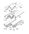
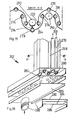
- FIG. 1 and 2 show sections of a separator according to the invention, which comprises channel-shaped open profile parts 10, 12, the edges 14, 16 of which engage behind such that chambers 18 form between the narrowing of the edges. (However, these are not necessarily necessary, as the illustration in FIG. 13 illustrates). Furthermore, the profile parts 10, 12 have projections 20 extending from the inner surface in the direction of the longitudinal axis, as a result of which further chambers 22, 24 are formed to the adjacent inner surface or to the edge of the adjacent profile part.
- the interlocking profile parts 10, 12 arranged in rows are now used to clean gaseous fluids such as cooling fluids, oil mists, air containing dirt particles and are assembled into so-called separators.
- gaseous fluids such as cooling fluids, oil mists, air containing dirt particles
- Each holding element 25, 44 consists of a plate-shaped base element 26, from which strip-shaped sections 28 and 30 extend and are angled in such a way that the mutually facing concave sections 32 and 34, at least in sections, comprise the outer surface 36 of the profile parts 12, the opening of which faces the fluids is.
- the sections 28 and 30 which are angled away from the base element 26 are also designed to be resilient in order to ensure that the profile parts 12 are held securely.
- the free ends of the strip-shaped sections 28 and 30 are directed away from one another, that is to say run approximately parallel to the base plate 26.
- the distance between the facing end sections 40, 42 from two successive holding elements 25, 44 is selected such that the lengthwise direction of the inner surface of the Profile part 10 extending projection 46 is detected.
- the shape of the projection 46 selected in the manner of a knob supports the holding between the sections 40, 42 of the holding elements 25, 44.
- the individual holding elements 25, 44 now only have to be strung together in a rail 48 of a holder 47 in order to fix the position guarantee.
- the holder 47 also has a leg 50 angled from the rail 48, which covers the profile parts 10, 12 in the end region, so that the fluids flowing through the profile parts 10, 12 cannot escape in the side region.
- the profile parts 10, 12 are consequently releasably fixed in the individual elements 25, 44 lined up in the holder 47, which enables problem-free cleaning or renewal of any damaged profile parts 10, 12.
- the opening Profile parts 10, 12 that face fluids are designed to be displaceable about their longitudinal axis, as a result of which a further influencing of the chamber cross-sections through which the fluids flow is made possible.
- FIGS. 1 and 2 differ fundamentally only in the form of the brackets 47 and 52, without otherwise having essential differences. Therefore, the same reference numerals have been chosen for the same elements. Irrespective of this, the construction of the profile parts 10 and 12 and their holding elements 25, 44 or holder 47, 52 provides a separator which can be designed without problems for the desired dimensions. This is made possible by the fact that the number of holding elements 25, 44 are lined up to one another and the profile parts 10, 12 are cut to the required length.
- the holding elements 25, 44 which comprise the sections 28, 30 to be referred to as spring elements, can consist, for example, of aluminum, stainless steel, spring steel or also plastic.
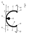
- a profile part 58 is shown which is held by a holder 56 and which in section has an essentially circular-arc-shaped geometry which extends beyond a semicircle. Furthermore, a protrusion 60 is provided in the apex region of the profile part 58, starting from an inner surface, which, as mentioned, increases the longitudinal rigidity of the profile part 58 and also leads to further chamber formation when interacting with edge sections of profile parts, which are not shown, which reach into the interior of the profile part 58 that have to flow the fluids to be cleaned.
- the chamber formation can be reinforced in that the edges 62, 64 of the profile part 58 are formed in a bead-like manner.
- the base element 66 from which two strip-shaped sections 68 and 70 having spring properties are angled, the outer surface in the vertically extending regions 72, 74 of the profile part 58 to determine it in sections.
- the essentially horizontal angled end sections 75, 76 are selected so that they capture a projection - in the manner of the reference number 60 provided - in the area of its taper 78. The profile parts facing the fluid with the outer surfaces are thereby fastened.
- the construction of the holding element 56 ensures that the profile part 58 can be rotated about its longitudinal axis, then flats 80 (FIG. 3) or 82 (FIG. 4) provided on the outer surface can fix the position. This ensures that an uncontrolled turning of the profile parts is not possible. Otherwise, the construction of FIG. 4 does not differ from that of FIG. 3, so that the same reference numerals are chosen for the same elements.
- brackets 230 for receiving channel-shaped profile parts are to be emphasized in particular, the basic idea of the embodiments of FIGS. 1 and 2 being retained.
- angled legs 234, 236, 238, 244 start from a base element 232 or 242 and are assigned to one another in pairs.
- the legs 234 and 236 are assigned to one another in order to partially grip around a profile part, not shown, which faces the fluids to be cleaned with its opening, and thus to hold it in place. Accordingly, legs 234 and 236 perform the function of sections 32 and 34 of FIG. 1.
- the further legs 238 and 240 of the base element 232 and the legs 244 of the base element 242 serve to receive the projections of the profile parts, the openings of which face away from the ascending and to be cleaned fluids.
- the end regions 258 and 260 of the legs 240 and 244 have deformations which are adapted to the geometry of the inner protrusion.
- the end sections 258 and 260 consequently fulfill the task of the regions 40 and 42 of the holder according to FIG. 1.
- the base elements 232 and 242 with the projecting legs 234, 236, 238, 240, 244 are then strung together in mounting rails 246 in order to detachably receive profile parts.
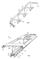
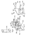
- a separator 84 is shown purely schematically in perspective and in the cutout, in which profile parts, not shown, are assembled into two surfaces which enclose an acute angle to one another.
- the separator 84 has, in section, V-shaped mutually aligned separating surfaces through which fluids to be cleaned flow in order to be fed via the interior 86 of the separator 84 to a ventilation opening 88 through which the cleaned fluids are sucked off.
- the profile parts used in the separator 84 correspond to those of FIGS. 1-4, so that in this respect reference is made to their geometry.
- the holding elements receiving the profile parts are designed in the manner of a profile strip 90 which has mutually alternating cutouts 92 and 94.
- the holding strips 90 can consist of rubber or plastic or steel springs, so they have a certain spring property, so that not only a safe, but also a low-noise holding of the profile parts takes place.
- the holding strips 90 themselves can be accommodated in rails 96 or 98 by holders 100.
- the holding strips 90 have web-like legs 103 and 104 running in one plane in the upper edge region. (Of course, the holding strips 90 can also be replaced by the holding elements 26 or 44 and vice versa.)
- the holding elements receiving the holding strips 90 are coupled to one another via, for example, a linkage or cable pulls 102 in such a way that they can be tilted in the same direction in such a way that the angle of inclination of the surface formed from the interlocking profile parts is adjustable.
- the separator 84 according to FIG. 5 also has the advantage that profiles which are available by the meter and can only be cut to the desired extent can be used for the individual profile parts.
- the entire separator 84 also no longer requires a rigid frame, as is known from the prior art.
- the profile parts are also detachably arranged in the separator 84, so that problem-free cleaning or renewal is possible.
- FIG. 6 shows that in the apex region of the recess 92, in which the profile parts are introduced, the opening of which is directly facing the fluids, a flattening 106 is provided in order to precisely position the profile parts, which provide a corresponding flattening have on the outer surface, as has been described in connection with the profile part of FIGS. 3 and 4.
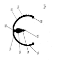
- FIG. 9 A sectional view of an embodiment of a further profile part 154 according to the invention can be seen in FIG. 9. It can be seen that the profile part 154 has an arc shape, the free edges of which are formed facing one another. A projection 158 extending in its longitudinal direction extends from the inner surface of the profile part 154, as a result of which a further subdivision into chambers of the space surrounding the profile part 154 or the spaces is formed which are formed by the further profile parts engaging in the profile part 154. This has a further influence on the flow velocity of the fluids, which in turn increases the degree of separation considerably.
- the projection 158 has a teardrop shape in section, that is to say it consists of a neck 160 and a subsequent main body 162 which first widens and then tapers towards the tip.
- a profile which is exemplary is shown in the drawing in the form of projections and recesses 164. This causes an additional swirling of the fluids flowing past, which not only increases the degree of separation, but also self-cleaning of the outer surface of the projection 158 is effected.
- a corresponding separator constructed from the profile parts 154 according to the invention requires less maintenance.
- a corresponding profiling can also be provided on the inner and / or outer surface of the profile part 154. This can also be formed by projections or recesses 166 or surface sections describing angles to one another.
- the free edges of the profile part 154 are reinforced, such as, for example, in the form of beads, which additionally influences the speed of the fluids flowing past.
- the profile part according to FIG. 9 can also be detachably arranged in a frame.
- a flattening 156 is provided.
- the profile parts 154 can also be introduced into a frame in a fixed, ie non-releasable, manner.
- a further projection 158 preferably projecting inwards from the central region, is provided in the profile part 154, as a result of which additional chamber formations occur which influence the speed of the fluids flowing through in such a way that an increased degree of separation and thus cleaning thereof is ensured.
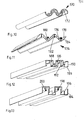
- FIGS. 10-16 Further embodiments of the design of profile parts can be seen in FIGS. 10-16.
- profile parts 10 are designed as hollow profiles, with the projection 172 running along the longitudinal axis also being hollow.
- Corresponding profile parts 170 can optionally be flowed through by media of adjustable temperature in order to achieve a targeted separation of particles or fluids within the profile parts 10 at desired locations, so that cleaning is additionally facilitated.
- the profile part 174 according to FIG. 11 can be referred to in cross section as V-shaped, the edges 176, 178 of the profile parts facing one another being able to run parallel to one another.
- the inner projections 180, 182 and 184 can have different geometries, for. B. show a rectangular shape, a circular shape or a teardrop shape in its free end region. The front ends each extend from the inner surface of the profile part 174 via a web.
- FIGS. 12 and 13 The possibility of also forming the profile parts in an angular manner is illustrated by FIGS. 12 and 13.
- the profile parts 185 according to FIG. 12 have an angular U-shape in section, the free ends 186 and 188 of the side legs 190 and 192 being angled inwards and running in one plane. This also results in a chamber formation of two interlocking profile parts 185.
- the profile parts 194 according to FIG. 13 have a pure angular U-shape, the inner projections 196, 198 and 200 being able to show different geometries.
- a shape can also be selected in which the web changes into a configuration which is circular in shape (reference number 200) or rhombus-like (reference number 198).
- the profile parts 202 are essentially in their shape which z. B. Figs. 4 and 9 simulated.
- the inner projection 204 is formed by a tubular element which extends in the longitudinal direction of the profile part 202 and through which a temperature which can be set may flow.
- the element which forms the projection 204 can extend from the inner surface of the profile element 202 or can also be completely integrated in the tube, as is indicated in the profile part 206 with the inner projection 208.
- profile parts 218 which have tubular elements 220, 222 and 224 in the central region and in the edge regions, a further tube 228 running from the central element 220 via a web 226 along the longitudinal axis of the profile part 218, so as to to form an inner projection.
- FIGS. 18 and 19 show a further embodiment of a separator 262 according to the invention, which consists of arcuate profile parts 264 and 266, which in turn can be adjusted with regard to the temperature.
- tubular elements 268, 270, 272 or 274, 276 and 278 are arranged on a circular section in order to come into intimate contact with them by clipping on the profile parts 264 and 266.
- the profile elements 264 and 266 are preferably extruded or rolled and are made of aluminum.
- a medium of adjustable temperature can now flow through the pipe elements 268, 270, 272, 274, 276 and 278, such as water or a gas.
- a perforated plate 282 is assigned to the end openings of the tubes 268 to 278 in such a way that media of the desired temperature can flow into the tube elements 268 to 278 from a subsequent space to be designated as chamber 284, which in turn is closed by a closed sheet metal element 286.
- the composite elements 280, 282 and 286, which, as mentioned, run at the ends of the profile parts 266 and 264 or the tube elements 268 to 278, are shown in the lower part of FIG. 18.
- the individual sheet metal elements 280, 282 and 286 are shown pulled apart. It can be seen that the element 286 has an inlet opening 288 through which the media can flow into the chamber 284 and thus into the tube elements 268 to 278.
- a further tubular element 290 or 292 can be arranged between the overlapping profile parts 264 and 266, which also opens into the chamber 284 in order to be flowed through by a medium of adjustable temperature.
- the degree of separation can be further increased by the additional tubular elements 290 and 292.
- tubular elements 290 and 292 also extend from the holding elements 280 to 282 arranged on the end face, these can be freely arranged between and spaced from the profile parts or, like the profile part 292, can be connected to the central tubular elements 268 via a web-shaped element 294.
- the elements 290 and 292 essentially perform the function of the inner projection, as has been described above with the aid of numerous exemplary embodiments.
- FIGS. 18 and 19 have the advantage that the profile parts 264 and 266 are detachably connected to the tubular elements 268 to 278, so that they can be easily removed and thus cleaned. Separators of desired surfaces can also be produced without any problems, since the individual elements only have to be cut to the required extent in order to subsequently be connected to the holding elements, such as sheet metal elements 280 and 282, which run at the end.
- FIG. 7 and 8 are intended to illustrate a further embodiment of separators 108 and 110, respectively, which can be arranged inclined with respect to the rising fluids to be cleaned.
- Sectional sections 114 and 116 are sections, a collection space 118 and 120, in which dirt such as separated oil can be collected.
- To clean the separator 108 or 110 only the separated liquid then has to be drained without the profile parts 114, 116 themselves necessarily having to be cleaned. This gives a decisive advantage over conventional separator plates. With these knitted fabric filters or vortex separator plates, the grease runs into the interior of the housing in order to be drained from there. However, this is hardly possible because the grease hardens in the housing and the drainage element sticks together.
- profile parts can be assembled into separator plates in order to be used in known frames or hoods.
- the above-described properties of the releasable arrangement of the profile parts possibly their adjustability or the collection of z.
- profile parts according to the invention which are arranged one above the other, are arranged in rows in different planes 122, 124 and 126 in order to enable a multi-stage deposition.
- the profile parts 128 arranged in the individual levels 122, 124 and 126 are detachably arranged in frame elements 130, 132 and 134, so that problem-free cleaning is possible.
- the embodiment of FIG. 17 results in a cascade arrangement which ensures that the fluid emerging from the top level 126 is completely cleaned.
Landscapes
- Chemical & Material Sciences (AREA)
- Engineering & Computer Science (AREA)
- Chemical Kinetics & Catalysis (AREA)
- Combustion & Propulsion (AREA)
- Mechanical Engineering (AREA)
- General Engineering & Computer Science (AREA)
- Separating Particles In Gases By Inertia (AREA)
- Turbine Rotor Nozzle Sealing (AREA)
Priority Applications (1)
| Application Number | Priority Date | Filing Date | Title |
|---|---|---|---|
| AT86108199T ATE57312T1 (de) | 1985-06-19 | 1986-06-16 | Abscheider fuer gasfoermige fluide. |
Applications Claiming Priority (6)
| Application Number | Priority Date | Filing Date | Title |
|---|---|---|---|
| DE19858517835 DE8517835U1 (de) | 1985-06-19 | 1985-06-19 | Abscheider für gasförmige Fluide |
| DE3521927 | 1985-06-19 | ||
| DE19853521927 DE3521927A1 (de) | 1985-06-19 | 1985-06-19 | Abscheider fuer gasfoermige fluide |
| DE3535911 | 1985-10-08 | ||
| DE3535911 | 1985-10-08 | ||
| DE19853542358 DE3542358A1 (de) | 1985-06-19 | 1985-11-29 | Abscheider fuer gasfoermige fluide |
Publications (2)
| Publication Number | Publication Date |
|---|---|
| EP0206204A1 true EP0206204A1 (fr) | 1986-12-30 |
| EP0206204B1 EP0206204B1 (fr) | 1990-10-10 |
Family
ID=39595650
Family Applications (1)
| Application Number | Title | Priority Date | Filing Date |
|---|---|---|---|
| EP86108199A Expired - Lifetime EP0206204B1 (fr) | 1985-06-19 | 1986-06-16 | Séparateur pour fluide gazeux |
Country Status (5)
| Country | Link |
|---|---|
| US (2) | US4830644A (fr) |
| EP (1) | EP0206204B1 (fr) |
| CA (1) | CA1275944C (fr) |
| DE (1) | DE3542358A1 (fr) |
| YU (1) | YU45785B (fr) |
Cited By (11)
| Publication number | Priority date | Publication date | Assignee | Title |
|---|---|---|---|---|
| WO1988004952A1 (fr) * | 1987-01-01 | 1988-07-14 | Gutermuth Paul Sen | Separateur pour fluides gazeux |
| EP0280160A1 (fr) * | 1987-02-18 | 1988-08-31 | Gutermuth, Paul, sen. | Dispositif de séparation pour des fluides gazeux |
| EP0306807A1 (fr) * | 1987-09-05 | 1989-03-15 | Gutermuth, Paul, sen. | Dispositif pour purifier des fluides gazeux |
| EP0375357A1 (fr) * | 1988-12-22 | 1990-06-27 | Protectaire Systems Company | Système de surfaces de rebondissement remplaçables |
| EP0402089A1 (fr) * | 1989-06-09 | 1990-12-12 | Foster Wheeler Energy Corporation | Réacteur à lit fluidifié utilisant un séparateur des matières solides interne |
| WO1990014875A1 (fr) * | 1989-06-05 | 1990-12-13 | Jeven Oy | Unite de filtration |
| WO1991016580A1 (fr) * | 1990-04-25 | 1991-10-31 | Gutermuth Paul Sen | Dispositif d'amenee d'air |
| FR2677269A1 (fr) * | 1991-06-05 | 1992-12-11 | Gerard Balitout | Dispositif de filtration et de separation de particules en suspension. |
| DE19603689A1 (de) * | 1996-02-02 | 1997-08-28 | Gutermuth Patent Gmbh & Co Kg | Abscheider |
| WO2003055574A1 (fr) * | 2001-12-22 | 2003-07-10 | Munters Euroform Gmbh | Profile de retenue pour lamelles, unite de profile de retenue modulaire et unite de separation, de reduction de lumiere ou de conduction de flux ainsi equipee |
| EP3677844A3 (fr) * | 2019-01-04 | 2021-06-02 | Stalgast Radom Sp. z o.o. | Filtre de hotte de cuisine |
Families Citing this family (38)
| Publication number | Priority date | Publication date | Assignee | Title |
|---|---|---|---|---|
| DE9013468U1 (de) * | 1990-09-25 | 1991-02-21 | Gutermuth Sen., Paul, 6456 Langenselbold | Abscheider |
| DE4127722C1 (en) * | 1991-08-22 | 1993-02-04 | Gif Gesellschaft Fuer Ingenieurprojekte Freiburg Mbh, 7800 Freiburg, De | Building ventilation moisture trap - has upwardly curved parallel sides offset to define flow chamber |
| DE4131988C2 (de) * | 1991-09-26 | 1995-05-11 | Rentschler Reven Lueftungssyst | Abscheider für Flüssigkeiten aus einem Gasstrom, insbesondere für Ölnebel |
| JPH06206011A (ja) * | 1992-12-04 | 1994-07-26 | Richerson Ben M | サイクロン分離器 |
| US5788729A (en) * | 1996-07-12 | 1998-08-04 | Carrier Corporation | Adjustable filter track |
| IT1290662B1 (it) * | 1997-02-04 | 1998-12-10 | Bafera Lucio | Unita' filtrante multifunzionale per cappe aspiranti e/o filtranti. |
| US6010554A (en) * | 1997-06-23 | 2000-01-04 | Battelle Memorial Institute | Micro-machined virtual impactor and method of operation |
| US6698592B2 (en) | 1998-11-13 | 2004-03-02 | Mesosystems Technology, Inc. | Virtual impactor |
| US8173431B1 (en) | 1998-11-13 | 2012-05-08 | Flir Systems, Inc. | Mail screening to detect mail contaminated with biological harmful substances |
| US6062392A (en) * | 1998-11-13 | 2000-05-16 | Mesosystems Technology, Inc. | Micromachined virtual impactor |
| US6110247A (en) * | 1998-11-13 | 2000-08-29 | Mesosystems Technology, Inc. | Micromachined impactor pillars |
| US6120573A (en) * | 1998-11-13 | 2000-09-19 | Mesosystems Technology, Inc. | Micromachined teardrop-shaped virtual impactor |
| US6290742B1 (en) * | 1999-12-23 | 2001-09-18 | Durr Industries, Inc. | Baffle system for separating liquid from a gas stream |
| US6322603B1 (en) * | 2000-07-10 | 2001-11-27 | The Babcock & Wilcox Company | Particulate collector channel with cooling inner elements in a CFB boiler |
| EP1363718A2 (fr) * | 2001-03-01 | 2003-11-26 | Phillips Plastics Corporation | Milieu filtrant de particules inorganiques poreuses |
| US7041159B2 (en) * | 2003-08-04 | 2006-05-09 | Phillips Plastics Corporation | Separation apparatus |
| US6454825B1 (en) * | 2001-03-27 | 2002-09-24 | Alex Cheimets | Exhaust baffle filter |
| DE10127678B4 (de) * | 2001-06-10 | 2004-02-05 | Brigitte Schmalhofer | Luftfilter und Verfahren zu seinem Betrieb |
| US6623551B2 (en) * | 2001-09-12 | 2003-09-23 | Durr Industries, Inc. | Baffle system for separating liquid from a gas stream |
| US7166140B2 (en) * | 2003-10-22 | 2007-01-23 | Phillips Plastics Corporation | High capture efficiency baffle |
| WO2005043044A1 (fr) * | 2003-10-22 | 2005-05-12 | Phillips Plastics Corporation | Deflecteur a grand pouvoir d'arret |
| DE102005019831A1 (de) * | 2005-04-28 | 2006-11-02 | BSH Bosch und Siemens Hausgeräte GmbH | Filteranordnung für Dunstabzugshaube |
| US7947123B2 (en) | 2006-11-10 | 2011-05-24 | Illinois Tool Works Inc. | Impact filter with grease trap |
| US20080202083A1 (en) * | 2007-02-23 | 2008-08-28 | Thomas Graham | Grease filter |
| WO2009023314A2 (fr) | 2007-05-09 | 2009-02-19 | Icx Technologies | Analyse par balayage de colis postaux à l'aide de technologies de détection multiples |
| DE102008064042B4 (de) * | 2008-12-19 | 2011-06-01 | Rentschler Reven-Lüftungssysteme GmbH | Plattenförmiger Abscheider für Flüssigkeiten aus einem Gasstrom |
| KR100893833B1 (ko) | 2008-12-30 | 2009-04-17 | 이호성 | 오염물질 분리요소 및 이 분리요소가 포함된 오염물질 분리장치 |
| US8243274B2 (en) | 2009-03-09 | 2012-08-14 | Flir Systems, Inc. | Portable diesel particulate monitor |
| CN102297465B (zh) * | 2010-06-28 | 2014-05-21 | 正太平洋(中国)厨具有限公司 | 斜背式排油烟机的接油盘结构 |
| CN103994563B (zh) * | 2013-02-19 | 2016-12-28 | 台达电子工业股份有限公司 | 用于散热器的防尘装置 |
| US10137395B2 (en) | 2013-10-11 | 2018-11-27 | Samsung Electronics Co., Ltd. | Grease filter, manufacturing method thereof and cooking device having the same |
| CN103900133B (zh) * | 2014-03-13 | 2016-11-23 | 宁波方太厨具有限公司 | 一种滤油装置及其旋转碰撞滤油结构 |
| US10100734B2 (en) * | 2015-02-24 | 2018-10-16 | Honeywell International Inc. | Multi-channel particle separator |
| DE202015102560U1 (de) * | 2015-05-19 | 2016-08-22 | Woco Industrietechnik Gmbh | Vorrichtung zur Abscheidung von Partikeln aus einem Gasstrom |
| CN105854426B (zh) * | 2016-05-13 | 2023-09-12 | 新乡市天诚航空净化设备有限公司 | 惯性除尘器 |
| EP3363519B1 (fr) * | 2017-02-20 | 2022-01-19 | Electrolux Appliances Aktiebolag | Filtre pour une hotte de cuisine |
| US10506903B2 (en) * | 2017-09-14 | 2019-12-17 | Skitter & Squirt Adventures, Llc | System and method for vacuum-powered debris separation |
| US11446597B2 (en) * | 2020-11-18 | 2022-09-20 | Bsh Home Appliances Corporation | Feathered baffle filter |
Citations (5)
| Publication number | Priority date | Publication date | Assignee | Title |
|---|---|---|---|---|
| CH550018A (de) | 1973-03-20 | 1974-06-14 | Hess & Cie Pilgersteg | Vorrichtung zum abscheiden von daempfen aus einem luftstrom. |
| DE2641765A1 (de) | 1976-09-16 | 1978-03-30 | Paul Gutermuth | Vorrichtung zum abscheiden von kondensierbaren anteilen |
| DE2720201A1 (de) * | 1977-05-05 | 1978-11-16 | Guenter Wimboeck | Fettfanggitter |
| FR2388532A1 (fr) * | 1977-04-27 | 1978-11-24 | Gif Ges Ingenieurprojekte | Installation pour realiser la ventilation et l'aeration de locaux avec atmosphere humide et/ou chargee de matieres grasses |
| DE3227005A1 (de) * | 1982-07-20 | 1984-01-26 | GIF Gesellschaft für Ingenieurprojekte Freiburg mbH, 7800 Freiburg | Vorrichtung zum entlueften von raeumen |
Family Cites Families (14)
| Publication number | Priority date | Publication date | Assignee | Title |
|---|---|---|---|---|
| US422056A (en) * | 1890-02-25 | Rubber-stamp holder | ||
| US972534A (en) * | 1910-05-18 | 1910-10-11 | John Hickey | Dust-arrester. |
| FR500690A (fr) * | 1918-10-23 | 1920-03-20 | J H Carruthers & Cio Ltd Soc | Perfectionnements aux appareils pour la séparation des matières grasses de l'eau |
| US1906874A (en) * | 1931-12-26 | 1933-05-02 | Arthur I Platt | Implement holder |
| US2287425A (en) * | 1941-08-27 | 1942-06-23 | Joseph H Fox | Display holder |
| US2523529A (en) * | 1949-07-01 | 1950-09-26 | Worthington Pump & Mach Corp | Eliminator for refrigeration system evaporators |
| BE494655A (fr) * | 1950-03-20 | |||
| US3251069A (en) * | 1964-03-09 | 1966-05-17 | Plastronics Inc | Inlet tube stabilizer for flexible container |
| US3343684A (en) * | 1965-10-21 | 1967-09-26 | Vincent Q Galier | Shuffleboard cue hanger |
| US3515284A (en) * | 1967-08-18 | 1970-06-02 | Cyril Taylor | Spring clip assemblies |
| US3566585A (en) * | 1969-07-07 | 1971-03-02 | Mona A Voloshen | Grease-extracting apparatus |
| US3910782A (en) * | 1973-09-27 | 1975-10-07 | Buildex Inc | Baffle type grease filter |
| US3834135A (en) * | 1973-10-02 | 1974-09-10 | A Jordan | Grease filter |
| DE2901748A1 (de) * | 1979-01-17 | 1980-07-31 | Manfred Goettlicher | Halter fuer laengliche gegenstaende |
-
1985
- 1985-11-29 DE DE19853542358 patent/DE3542358A1/de not_active Withdrawn
-
1986
- 1986-06-16 EP EP86108199A patent/EP0206204B1/fr not_active Expired - Lifetime
- 1986-06-18 YU YU106086A patent/YU45785B/sh unknown
- 1986-06-19 CA CA000511918A patent/CA1275944C/fr not_active Expired - Lifetime
-
1988
- 1988-01-11 US US07/144,617 patent/US4830644A/en not_active Expired - Fee Related
- 1988-08-18 US US07/234,131 patent/US4877430A/en not_active Expired - Fee Related
Patent Citations (6)
| Publication number | Priority date | Publication date | Assignee | Title |
|---|---|---|---|---|
| CH550018A (de) | 1973-03-20 | 1974-06-14 | Hess & Cie Pilgersteg | Vorrichtung zum abscheiden von daempfen aus einem luftstrom. |
| DE2641765A1 (de) | 1976-09-16 | 1978-03-30 | Paul Gutermuth | Vorrichtung zum abscheiden von kondensierbaren anteilen |
| FR2388532A1 (fr) * | 1977-04-27 | 1978-11-24 | Gif Ges Ingenieurprojekte | Installation pour realiser la ventilation et l'aeration de locaux avec atmosphere humide et/ou chargee de matieres grasses |
| DE2718611B2 (de) | 1977-04-27 | 1980-07-10 | GIF Gesellschaft für Ingenieurprojekte Freiburg mbH, 7800 Freiburg | Abscheider für eine Einrichtung zum Be- und Entlüften von Räumen |
| DE2720201A1 (de) * | 1977-05-05 | 1978-11-16 | Guenter Wimboeck | Fettfanggitter |
| DE3227005A1 (de) * | 1982-07-20 | 1984-01-26 | GIF Gesellschaft für Ingenieurprojekte Freiburg mbH, 7800 Freiburg | Vorrichtung zum entlueften von raeumen |
Cited By (12)
| Publication number | Priority date | Publication date | Assignee | Title |
|---|---|---|---|---|
| WO1988004952A1 (fr) * | 1987-01-01 | 1988-07-14 | Gutermuth Paul Sen | Separateur pour fluides gazeux |
| EP0280160A1 (fr) * | 1987-02-18 | 1988-08-31 | Gutermuth, Paul, sen. | Dispositif de séparation pour des fluides gazeux |
| EP0306807A1 (fr) * | 1987-09-05 | 1989-03-15 | Gutermuth, Paul, sen. | Dispositif pour purifier des fluides gazeux |
| EP0375357A1 (fr) * | 1988-12-22 | 1990-06-27 | Protectaire Systems Company | Système de surfaces de rebondissement remplaçables |
| WO1990014875A1 (fr) * | 1989-06-05 | 1990-12-13 | Jeven Oy | Unite de filtration |
| EP0402089A1 (fr) * | 1989-06-09 | 1990-12-12 | Foster Wheeler Energy Corporation | Réacteur à lit fluidifié utilisant un séparateur des matières solides interne |
| WO1991016580A1 (fr) * | 1990-04-25 | 1991-10-31 | Gutermuth Paul Sen | Dispositif d'amenee d'air |
| FR2677269A1 (fr) * | 1991-06-05 | 1992-12-11 | Gerard Balitout | Dispositif de filtration et de separation de particules en suspension. |
| DE19603689A1 (de) * | 1996-02-02 | 1997-08-28 | Gutermuth Patent Gmbh & Co Kg | Abscheider |
| WO2003055574A1 (fr) * | 2001-12-22 | 2003-07-10 | Munters Euroform Gmbh | Profile de retenue pour lamelles, unite de profile de retenue modulaire et unite de separation, de reduction de lumiere ou de conduction de flux ainsi equipee |
| EP3677844A3 (fr) * | 2019-01-04 | 2021-06-02 | Stalgast Radom Sp. z o.o. | Filtre de hotte de cuisine |
| EP3978812A1 (fr) | 2019-01-04 | 2022-04-06 | Stalgast Radom Sp. z o.o. | Filtre de hotte de cuisine |
Also Published As
| Publication number | Publication date |
|---|---|
| DE3542358A1 (de) | 1987-01-02 |
| CA1275944C (fr) | 1990-11-06 |
| EP0206204B1 (fr) | 1990-10-10 |
| YU45785B (sh) | 1992-07-20 |
| YU106086A (en) | 1988-08-31 |
| US4830644A (en) | 1989-05-16 |
| US4877430A (en) | 1989-10-31 |
Similar Documents
| Publication | Publication Date | Title |
|---|---|---|
| EP0206204B1 (fr) | Séparateur pour fluide gazeux | |
| EP3374054B1 (fr) | Dispositif d'aspiration de fumées | |
| EP0007385A1 (fr) | Filtre pour la séparation des particules de matière grasse d'un courant gazeux, notamment de buée de cuisine, ainsi que canal d'évacuation d'air à cet effet | |
| EP1362208B1 (fr) | Hotte aspirante avec un filtre pour graisses | |
| DD259143A5 (de) | Abscheider fuer gasfoermige fluide | |
| EP0059768B1 (fr) | Gouttière de support pour éléments de plafonds | |
| DE4427074A1 (de) | Mechanisches Abscheidegitter zum Abscheiden von Flüssigkeits- und/oder Feststoffpartikeln aus einem Gasstrom | |
| EP0438676B1 (fr) | Dispositif pour séparer des fluides | |
| EP0148289B1 (fr) | Sous-plafond à filtre pour séparer et déposer des matières en suspension dans de l'air d'échappement ascendant | |
| DE8307964U1 (de) | Wirbelstromfilter mit fett- und schmutzfanggitter | |
| DE3145548A1 (de) | "vorrichtung zum be- und/oder entlueften von raeumen" | |
| DE19501282C2 (de) | Tropfenabscheider sowie Lamellenhalter hierfür | |
| DE8517835U1 (de) | Abscheider für gasförmige Fluide | |
| DE10237376B4 (de) | Vorrichtung zum Abscheiden von gasgetragenen Bestandteilen | |
| DE3103231C2 (de) | Schalldämpfer | |
| DE7524852U (de) | Fettfangfilter | |
| EP0306807B1 (fr) | Dispositif pour purifier des fluides gazeux | |
| DE102012007873B4 (de) | Lamellenabscheider mit Auffangwanne | |
| EP1980310B1 (fr) | Dispositif de séparation de gouttes de liquide de flux de gaz avec des tiges et des lamelles | |
| DE29921370U1 (de) | Mechanischer Abscheider zum Abscheiden von Flüssigkeits- und/oder Feststoffpartikeln aus einem Gasstrom | |
| DE3524928C1 (de) | Vorrichtung zum Reinigen der Oberseiten von Deckenbauteilen | |
| AT396546B (de) | Dunstabzugshaube od.dgl. | |
| EP0667497A1 (fr) | Arrangement pour ventilation d'air | |
| DE10064911A1 (de) | Aerosolabscheider | |
| DE20023285U1 (de) | Aerosolabscheider |
Legal Events
| Date | Code | Title | Description |
|---|---|---|---|
| PUAI | Public reference made under article 153(3) epc to a published international application that has entered the european phase |
Free format text: ORIGINAL CODE: 0009012 |
|
| AK | Designated contracting states |
Kind code of ref document: A1 Designated state(s): AT BE CH DE FR GB IT LI LU NL SE |
|
| 17P | Request for examination filed |
Effective date: 19870424 |
|
| 17Q | First examination report despatched |
Effective date: 19880713 |
|
| GRAA | (expected) grant |
Free format text: ORIGINAL CODE: 0009210 |
|
| AK | Designated contracting states |
Kind code of ref document: B1 Designated state(s): AT BE CH DE FR GB IT LI LU NL SE |
|
| REF | Corresponds to: |
Ref document number: 57312 Country of ref document: AT Date of ref document: 19901015 Kind code of ref document: T |
|
| REF | Corresponds to: |
Ref document number: 3674841 Country of ref document: DE Date of ref document: 19901115 |
|
| ITF | It: translation for a ep patent filed | ||
| ET | Fr: translation filed | ||
| GBT | Gb: translation of ep patent filed (gb section 77(6)(a)/1977) | ||
| PLBI | Opposition filed |
Free format text: ORIGINAL CODE: 0009260 |
|
| 26 | Opposition filed |
Opponent name: RENTSCHLER REVEN-LUEFTUNGSSYSTEME GMBH Effective date: 19910709 |
|
| NLR1 | Nl: opposition has been filed with the epo |
Opponent name: RENTSCHLER REVEN-LUEFTUNGSSYSTEME GMBH |
|
| PLBM | Termination of opposition procedure: date of legal effect published |
Free format text: ORIGINAL CODE: 0009276 |
|
| STAA | Information on the status of an ep patent application or granted ep patent |
Free format text: STATUS: OPPOSITION PROCEDURE CLOSED |
|
| 27C | Opposition proceedings terminated |
Effective date: 19921017 |
|
| ITTA | It: last paid annual fee | ||
| NLR2 | Nl: decision of opposition | ||
| EPTA | Lu: last paid annual fee | ||
| EAL | Se: european patent in force in sweden |
Ref document number: 86108199.0 |
|
| NLS | Nl: assignments of ep-patents |
Owner name: GUTERMUTH PATENT GMBH & CO. KG TE LANGENSELBOLD, B |
|
| PGFP | Annual fee paid to national office [announced via postgrant information from national office to epo] |
Ref country code: CH Payment date: 19950523 Year of fee payment: 10 |
|
| PGFP | Annual fee paid to national office [announced via postgrant information from national office to epo] |
Ref country code: SE Payment date: 19950524 Year of fee payment: 10 |
|
| PGFP | Annual fee paid to national office [announced via postgrant information from national office to epo] |
Ref country code: BE Payment date: 19950530 Year of fee payment: 10 |
|
| PGFP | Annual fee paid to national office [announced via postgrant information from national office to epo] |
Ref country code: LU Payment date: 19950601 Year of fee payment: 10 |
|
| PGFP | Annual fee paid to national office [announced via postgrant information from national office to epo] |
Ref country code: AT Payment date: 19950612 Year of fee payment: 10 |
|
| PGFP | Annual fee paid to national office [announced via postgrant information from national office to epo] |
Ref country code: NL Payment date: 19950629 Year of fee payment: 10 |
|
| REG | Reference to a national code |
Ref country code: GB Ref legal event code: 732E |
|
| ITPR | It: changes in ownership of a european patent |
Owner name: CESSIONE;GUTERMUTH PATENT GMBH & CO. KG |
|
| REG | Reference to a national code |
Ref country code: CH Ref legal event code: PUE Owner name: PAUL GUTERMUTH, SEN. TRANSFER- GUTERMUTH PATENT GM Ref country code: CH Ref legal event code: NV Representative=s name: PATENTANWALTSBUREAU BOSSHARD UND LUCHS |
|
| REG | Reference to a national code |
Ref country code: FR Ref legal event code: TP |
|
| REG | Reference to a national code |
Ref country code: FR Ref legal event code: TP |
|
| PG25 | Lapsed in a contracting state [announced via postgrant information from national office to epo] |
Ref country code: LU Free format text: LAPSE BECAUSE OF NON-PAYMENT OF DUE FEES Effective date: 19960616 Ref country code: AT Effective date: 19960616 |
|
| PG25 | Lapsed in a contracting state [announced via postgrant information from national office to epo] |
Ref country code: SE Effective date: 19960617 |
|
| PG25 | Lapsed in a contracting state [announced via postgrant information from national office to epo] |
Ref country code: LI Effective date: 19960630 Ref country code: CH Effective date: 19960630 Ref country code: BE Effective date: 19960630 |
|
| BERE | Be: lapsed |
Owner name: GUTERMUTH PATENT G.M.B.H. & CO. K.G. Effective date: 19960630 |
|
| PG25 | Lapsed in a contracting state [announced via postgrant information from national office to epo] |
Ref country code: NL Effective date: 19970101 |
|
| REG | Reference to a national code |
Ref country code: CH Ref legal event code: PL |
|
| EUG | Se: european patent has lapsed |
Ref document number: 86108199.0 |
|
| NLV4 | Nl: lapsed or anulled due to non-payment of the annual fee |
Effective date: 19970101 |
|
| PGFP | Annual fee paid to national office [announced via postgrant information from national office to epo] |
Ref country code: GB Payment date: 19980615 Year of fee payment: 13 |
|
| PG25 | Lapsed in a contracting state [announced via postgrant information from national office to epo] |
Ref country code: GB Free format text: LAPSE BECAUSE OF NON-PAYMENT OF DUE FEES Effective date: 19990616 |
|
| GBPC | Gb: european patent ceased through non-payment of renewal fee |
Effective date: 19990616 |
|
| PGFP | Annual fee paid to national office [announced via postgrant information from national office to epo] |
Ref country code: FR Payment date: 20030627 Year of fee payment: 18 |
|
| PG25 | Lapsed in a contracting state [announced via postgrant information from national office to epo] |
Ref country code: FR Free format text: LAPSE BECAUSE OF NON-PAYMENT OF DUE FEES Effective date: 20050228 |
|
| REG | Reference to a national code |
Ref country code: FR Ref legal event code: ST |
|
| PG25 | Lapsed in a contracting state [announced via postgrant information from national office to epo] |
Ref country code: IT Free format text: LAPSE BECAUSE OF NON-PAYMENT OF DUE FEES;WARNING: LAPSES OF ITALIAN PATENTS WITH EFFECTIVE DATE BEFORE 2007 MAY HAVE OCCURRED AT ANY TIME BEFORE 2007. THE CORRECT EFFECTIVE DATE MAY BE DIFFERENT FROM THE ONE RECORDED. Effective date: 20050616 |
|
| PGFP | Annual fee paid to national office [announced via postgrant information from national office to epo] |
Ref country code: DE Payment date: 20050629 Year of fee payment: 20 |