EP0375357A1 - Système de surfaces de rebondissement remplaçables - Google Patents
Système de surfaces de rebondissement remplaçables Download PDFInfo
- Publication number
- EP0375357A1 EP0375357A1 EP89313273A EP89313273A EP0375357A1 EP 0375357 A1 EP0375357 A1 EP 0375357A1 EP 89313273 A EP89313273 A EP 89313273A EP 89313273 A EP89313273 A EP 89313273A EP 0375357 A1 EP0375357 A1 EP 0375357A1
- Authority
- EP
- European Patent Office
- Prior art keywords
- baffles
- disposable
- paint
- particulates
- overspray
- Prior art date
- Legal status (The legal status is an assumption and is not a legal conclusion. Google has not performed a legal analysis and makes no representation as to the accuracy of the status listed.)
- Granted
Links
- 238000000034 method Methods 0.000 title claims description 9
- 239000003973 paint Substances 0.000 claims abstract description 80
- 239000007921 spray Substances 0.000 claims abstract description 49
- XLYOFNOQVPJJNP-UHFFFAOYSA-N water Substances O XLYOFNOQVPJJNP-UHFFFAOYSA-N 0.000 claims abstract description 35
- 238000001914 filtration Methods 0.000 claims abstract description 14
- 239000000126 substance Substances 0.000 claims abstract description 12
- 239000000463 material Substances 0.000 claims description 31
- 239000003063 flame retardant Substances 0.000 claims description 9
- 230000002829 reductive effect Effects 0.000 claims description 9
- 238000005507 spraying Methods 0.000 claims description 8
- 238000000576 coating method Methods 0.000 claims description 6
- 239000011248 coating agent Substances 0.000 claims description 4
- 238000011045 prefiltration Methods 0.000 claims description 3
- 238000009736 wetting Methods 0.000 claims description 2
- 238000007599 discharging Methods 0.000 claims 3
- 238000009825 accumulation Methods 0.000 claims 2
- 239000010802 sludge Substances 0.000 abstract description 12
- 239000011087 paperboard Substances 0.000 abstract description 11
- 238000004140 cleaning Methods 0.000 abstract description 5
- 231100001261 hazardous Toxicity 0.000 abstract description 2
- 239000010852 non-hazardous waste Substances 0.000 abstract description 2
- -1 filter cleaning Substances 0.000 abstract 1
- 239000002245 particle Substances 0.000 description 12
- 239000007787 solid Substances 0.000 description 12
- 239000002184 metal Substances 0.000 description 9
- 239000004922 lacquer Substances 0.000 description 5
- 230000003014 reinforcing effect Effects 0.000 description 5
- 238000012423 maintenance Methods 0.000 description 4
- 239000000701 coagulant Substances 0.000 description 3
- 239000002904 solvent Substances 0.000 description 3
- RNFJDJUURJAICM-UHFFFAOYSA-N 2,2,4,4,6,6-hexaphenoxy-1,3,5-triaza-2$l^{5},4$l^{5},6$l^{5}-triphosphacyclohexa-1,3,5-triene Chemical compound N=1P(OC=2C=CC=CC=2)(OC=2C=CC=CC=2)=NP(OC=2C=CC=CC=2)(OC=2C=CC=CC=2)=NP=1(OC=1C=CC=CC=1)OC1=CC=CC=C1 RNFJDJUURJAICM-UHFFFAOYSA-N 0.000 description 2
- 239000000123 paper Substances 0.000 description 2
- 230000002093 peripheral effect Effects 0.000 description 2
- 229910001369 Brass Inorganic materials 0.000 description 1
- 238000010521 absorption reaction Methods 0.000 description 1
- 230000002411 adverse Effects 0.000 description 1
- 238000003491 array Methods 0.000 description 1
- 239000010951 brass Substances 0.000 description 1
- 238000010276 construction Methods 0.000 description 1
- 230000000694 effects Effects 0.000 description 1
- 238000004880 explosion Methods 0.000 description 1
- 230000009970 fire resistant effect Effects 0.000 description 1
- 238000007667 floating Methods 0.000 description 1
- 239000002920 hazardous waste Substances 0.000 description 1
- 230000000670 limiting effect Effects 0.000 description 1
- 239000007788 liquid Substances 0.000 description 1
- 230000014759 maintenance of location Effects 0.000 description 1
- 238000004519 manufacturing process Methods 0.000 description 1
- 230000035515 penetration Effects 0.000 description 1
- 230000000737 periodic effect Effects 0.000 description 1
- 238000011084 recovery Methods 0.000 description 1
- 230000000717 retained effect Effects 0.000 description 1
- 238000003892 spreading Methods 0.000 description 1
- 230000003068 static effect Effects 0.000 description 1
- 239000000758 substrate Substances 0.000 description 1
- 231100000331 toxic Toxicity 0.000 description 1
- 230000002588 toxic effect Effects 0.000 description 1
- 238000011144 upstream manufacturing Methods 0.000 description 1
- 238000009423 ventilation Methods 0.000 description 1
- 230000003442 weekly effect Effects 0.000 description 1
Images


Classifications
-
- B—PERFORMING OPERATIONS; TRANSPORTING
- B01—PHYSICAL OR CHEMICAL PROCESSES OR APPARATUS IN GENERAL
- B01D—SEPARATION
- B01D45/00—Separating dispersed particles from gases or vapours by gravity, inertia, or centrifugal forces
- B01D45/04—Separating dispersed particles from gases or vapours by gravity, inertia, or centrifugal forces by utilising inertia
- B01D45/08—Separating dispersed particles from gases or vapours by gravity, inertia, or centrifugal forces by utilising inertia by impingement against baffle separators
-
- B—PERFORMING OPERATIONS; TRANSPORTING
- B05—SPRAYING OR ATOMISING IN GENERAL; APPLYING FLUENT MATERIALS TO SURFACES, IN GENERAL
- B05B—SPRAYING APPARATUS; ATOMISING APPARATUS; NOZZLES
- B05B14/00—Arrangements for collecting, re-using or eliminating excess spraying material
- B05B14/40—Arrangements for collecting, re-using or eliminating excess spraying material for use in spray booths
- B05B14/44—Arrangements for collecting, re-using or eliminating excess spraying material for use in spray booths using walls specially adapted for promoting separation of the excess material from the air, e.g. baffle plates
-
- Y—GENERAL TAGGING OF NEW TECHNOLOGICAL DEVELOPMENTS; GENERAL TAGGING OF CROSS-SECTIONAL TECHNOLOGIES SPANNING OVER SEVERAL SECTIONS OF THE IPC; TECHNICAL SUBJECTS COVERED BY FORMER USPC CROSS-REFERENCE ART COLLECTIONS [XRACs] AND DIGESTS
- Y02—TECHNOLOGIES OR APPLICATIONS FOR MITIGATION OR ADAPTATION AGAINST CLIMATE CHANGE
- Y02P—CLIMATE CHANGE MITIGATION TECHNOLOGIES IN THE PRODUCTION OR PROCESSING OF GOODS
- Y02P70/00—Climate change mitigation technologies in the production process for final industrial or consumer products
- Y02P70/10—Greenhouse gas [GHG] capture, material saving, heat recovery or other energy efficient measures, e.g. motor control, characterised by manufacturing processes, e.g. for rolling metal or metal working
-
- Y—GENERAL TAGGING OF NEW TECHNOLOGICAL DEVELOPMENTS; GENERAL TAGGING OF CROSS-SECTIONAL TECHNOLOGIES SPANNING OVER SEVERAL SECTIONS OF THE IPC; TECHNICAL SUBJECTS COVERED BY FORMER USPC CROSS-REFERENCE ART COLLECTIONS [XRACs] AND DIGESTS
- Y10—TECHNICAL SUBJECTS COVERED BY FORMER USPC
- Y10S—TECHNICAL SUBJECTS COVERED BY FORMER USPC CROSS-REFERENCE ART COLLECTIONS [XRACs] AND DIGESTS
- Y10S55/00—Gas separation
- Y10S55/46—Spray booths
Definitions
- the present invention pertains to the filtering of airborne overspray from an airflow.
- Spray booths have long been used in many industrial applications to provide significant advantages in maintaining health and safety standards. In general, without spray booths, workers spraying paints, chemicals, or other materials onto a workpiece would be subject to overspray which is directed toward the workpiece, but which does not stay in contact therewith.
- One type of spray booth for removing such overspray typically has a ventilation system for establishing an airflow which induces the overspray to travel across one or more filtering stages.
- U.S. Patent No. 4,484,513 assigned to the assignee of the present invention, for example, discloses an improved spray booth having multiple water-wash stages.
- a first water-wash stage consists of vertically oriented metal baffles having very shallow flanges pointing in a direction opposite to the direction of the overspray.
- the shape of the baffles provides advantages in maintaining a water flow traveling across the flat, front surfaces of the baffles, i.e., those surfaces extending toward the overspray. Many of the airborne paint particles are trapped by the water flowing down the baffles and carried down the baffles to an underlying tank. Because these baffles are the first wash, a large amount of paint particles are trapped and carried into the tank down below the baffles.
- Chemical coagulants are added to the water to coagulate the paint particles collected in the water reservoir into a scum that floats and is removed by skimming techniques.
- the baffles are very effective as a first filtering stage, it has been found that the baffles over a period of time accumulate significant concentrations of overspray material, particularly on the edges of the baffles and extending away from the direction of overspray. This requires that periodic maintenance be performed on the baffles to wipe the accumulated paint from the metal baffles.
- the paint is a sticky material that does not readily wipe off.
- the amount of paint sludge accumulating in the tank is quite large and it must be removed either by shutting down the system and scooping out the paint or by sludge removal devices.
- the coagulant chemicals added to the water add to the yearly cost of running a spray booth as does the cost of cleaning the booth and its down time during cleaning.
- the amount of sludge collected is another problem since it may be hazardous waste which must be incinerated because of the toxic solvents retained in the paint sludge. Disposal costs for this collected paint sludge are normally about $300 per barrel.
- the present invention is directed toward providing increased both efficiency by providing a pre-baffle system which can collect approximately 80% of the overspray before the overspray reaches the usual filtering stages in the booth.
- the preferred pre-baffle system only reduces the air flow by about 1/16 or less so that the air flow requirements can still be maintained.
- the pre-baffle system can be made of disposable baffles which can be replaced, for example, on a weekly basis and which can be baked to remove the solvents from the paint sludge thereon to dry completely the paint on the baffles which then can be disposed of as non-hazardous waste.
- the amount of overspray impinging on the normal filter stages may be reduced to 20% so that the amount of sludge in the water and the amount of paint collected on the baffles or other filter elements in the booth is drastically reduced. Less cleaning, less water and less sludge on the booth filter stages results in substantial savings.
- the collection of 80% of the overspray on the pre-baffle system means that the dry filter panels need be changed only once in five times of the current changes. Also, improved air flow may be found in dry booths for longer periods of time because the pre-baffle system helps distribute the air more uniformly across the dry filter panel face. Without the pre-baffle system, the air tends to be more concentrated at the center of the panel face which first fills with paint and then the air and particles are forced outside of the center. This redirection of air in these dry filter booths causes air turbulence and adversely effects the spray pattern of paint being applied to an article in the booth. However, with the pre-baffle system the uniformity of the air pattern is improved in a dry booth to reduce the disturbance of the paint spray pattern.
- the pre-baffle system can collect 80% of the overspray, it has been found desirable to collect high solid paint overspray for re-use.
- the high cost of high solid paint and its retention of its liquid state makes it worthwhile to do so.
- the preferred baffles are made of inexpensive material and, after baking the high solid paints thereon, these disposable pre-baffles may be economically incinerated or lawfully used in a landfill.
- Another object of the present invention is to provide disposable pre-baffles which can be rapidly and easily exchanged when their useful life has expired.
- a further object of the present invention is to provide disposable pre-baffles which are easily fabricated from inexpensive materials such as fire-resistant paperboard.
- a spray booth is generally indicated at 10.
- the spray booth accommodates an article 11 being sprayed from a spray device 13.
- the article is located in a front section 12 of the spray booth, in front of a pre-baffle system 20, constructed according to principles of the present invention.
- articles 11 may be supported on a conveyor track 15 and passed laterally through front section 12, passing through openings 16, 17 formed in sidewalls 18, 19 of front section 12.
- the conveyor track 15 and other similar conveyor arrangements adapt spray booth 10 for use in a high production environment where the total volume of solid articles sprayed onto articles 11 and creating overspray can be very considerable.
- a fan 22 creates an air flow 24 in front section 12 of the spray booth, carrying the overspray in the vicinity of article 11 toward the rear of the spray booth. After being drawn through multiple filter stages the induced air is discharged by fan 22, as indicated by the arrows 32.
- the filter stages are wet filter stages which use water to wet the overspray and may be constructed according to United States Patent No. 4,484,513, a disclosure of which is herein incorporated by reference.
- the chamber 30, for example may contain two water-wash filter stages such as shown in FIG. 11 wherein a water wash baffle system 35 is used.
- the air having pushed through these wet baffles 39 flows downwardly and under an inclined wall 47 into a spray chamber 49 in which a water spray device 51 which causes a water spray and turbulence to wet overspray particles to cause them to drop into the reservoir 41.
- a water spray device 51 which causes a water spray and turbulence to wet overspray particles to cause them to drop into the reservoir 41.
- the present invention may also be used with so-called “dry booths" where filter media pads, mounted as removable panels, replace the water-wash stages described above.
- a pre-baffle system 20 using disposable, low cost, channel shaped baffles 21 are placed in front of the normal filtering means which may be in the form of water filters 35 and 49 such as disclosed in U.S. 4,484,513 or dry fibrous filter panels.
- the preferred pre-baffle system 20 may capture as much as 80% of the overspray so that only 20% of the overspray need be removed by the water wash filters 35 and 49. By removing as much as 80% of the overspray, the subsequent filters will not accumulate so much paint thereon and need not be cleaned so often.
- the spray booth emission can be cut substantially as shown by graphs in FIGS. 12 and 13.
- a standard booth with 96% efficiency and emitting 7.9 grains of particulate per 1,000 cfm can be improved to 1.58 grains with the addition of the pre-baffle system 20. In gallon of paint per year, this translates into 312 gallons without the invention and only 62 gallons after the pre-baffle system 20 is installed.
- the preferred and illustrated pre-baffle system is comprised of a plurality of inexpensive and disposal baffles 36 which are preferably made of paperboard impregnated with a fire retardant material.
- baffles 36 By making the baffles so cheaply, they may be used for a period of time, e.g., one week and then removed and disposed of. This is in contrast to the permanent metal baffles 39 that are made of more expensive material and are not connected in the booth for ready replacement as are the disposable filter baffles 36.
- the illustrated baffles usually begin to lose their shape and sag after one week as the paperboard material becomes wet and loses its strength and as the wet of paint accumulated thereon pulls downwardly on the baffle.
- the preferred baffles are channel shaped. Manifestly, the baffles 36 may be made of other materials and may have other shapes and fall within the purview of this invention.
- the filtering according to United States Patent No. 4,484,513 is more than 98% efficient in its removal of airborne overspray particles.
- the filter stage 20 When the filter stage 20 is placed upstream of the initial filter stage described in United States Patent No. 4,484,513, an even higher efficiency is achieved, and due to the efficient prefiltering the filter panel greatly extends the life of the downstream filter stages.
- the filter panel according to the present invention greatly reduces the chemical usage needed to treat the wash water so as to render the water effective as a wash media and so as to replenish water that has cycled through the filter stages, allowing a closed cycle operation with little or no make-up water.
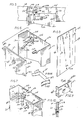
- the initial pre-baffle system 20 of the preferred embodiment comprises a filter panel 84 which is preferably constructed of a spaced-apart plurality of disposable filtering baffles 36 (see FIGS. 5-7).
- the disposable baffles 36 include an intermediate wall 38 having edges 40, 42 from which sidewalls 44, 46 extend in a direction toward the article 11, i.e., in the direction of overspray.
- the intermediate wall 38 and the sidewalls 44, 46 together comprise a channel having a recess 50 of generally U-shaped cross-sectional configuration.
- preferred baffles have their channel recesses 50 open toward the direction of overspray to accumulate as much overspray thereon as possible.
- the baffles 36 are preferably formed from an integral sheet or a blank 54 of inexpensive material so that they can be thrown away after usage.
- a typical material is a paperboard, or other suitable board-like paper product impregnated with a fire retardant chemical.
- the blank 54 is slit with a low and folded along lines. 56, 58 to form the sidewalls 44, 46.
- a low knife cut or score is a limited penetration of blank 54, and does not extend completely therethrough.
- mounting apertures 60, 62 are formed in the intermediate wall 38, adjacent the end of the baffle, and located intermediate the fold lines 56, 58 of blank 54. Referring especially to FIG. 10, an eyelet or hollow rivet is installed in each mounting aperture 62.
- the rivet includes enlarged faces 68, 70.
- Blank 54 is formed of paperboard stock. Other materials suitable for use in the baffles will be discussed below.
- the airflow through a commercial spray booth is quite large, typically in the range of 100 fpm or more.
- the air flows toward the open channels of the baffles and impinges paint particles on the intermediate wall 38, the interior surface 44a, 46a and the exterior surfaces 44b, of the sidewalls.
- the material from which the baffle is formed is preferably rigid and self-supporting.
- the baffles may be made of a material which does not have the strength or rigidity necessary to be self-supporting if a separate support structure is provided therefor.
- an open wire or expanded metal framework backing may be provided throughout substantial portions of the baffle length.
- the baffles be generally self-supporting so as to require only a minimum of supporting framework so that, when the filtering efficiency of the baffles drops below a desired limit, the only maintenance required is the replacement of the baffle.
- the first pre-baffle system 20 consists of a filter panel generally indicated at 84 comprising a spaced-apart plurality of baffles 36 mounted to a framework 86, supported by structural members of the spray booth.
- the framework 86 consists of two cross members 88, 90 laterally coextensive with the front section 12.
- the cross members 88, 90 are mounted with brackets (not shown) to a wall 92 in front section 12.
- Wall 92, facing article 11 and the direction of overspray, has a central opening 94.
- cross members 88, 90 are preferably U-shaped in cross-section so as to have two vertically extending walls, each wall supporting a row of baffles.
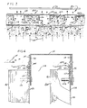
- FIG. 4 shows a cross member 88 having vertical walls 94, 96.
- the bottom cross member 90 has a similar U-shaped cross-section, with a central horizontal wall 98 intermediate a forward wall 100 and a rearward wall 102.
- the cross members 88, 90 form concave recesses generally opposing each other as can be seen in the right-hand portion of FIG. 1.
- the baffles In addition to the static loading on the baffles produced by the airflow, the baffles, due to their lightweight and relatively large surface area, could undergo a vibratory or fluttering motion during operation of the spray booth. However, vibratory fatigue, especially for paperboard baffles weakened by a high moisture environment, has not proven to be a problem with the filter apparatus according to the present invention.
- the mounting of the baffles with a brass eyelet and an elongated spring clip in addition to the substantial backing support provided by the cross members provides sufficient strength and support while allows easy replacement of the baffles.
- the framework 86 disposes the plurality of baffles in two spaced-apart planar arrays with the baffles of one planar array staggered with respect to the baffles of the other baffle array.
- the baffles in the frontal planar array of FIG. 3 are spaced apart by a distance d significantly less than the width r of the baffle recess 50.
- the baffles of the rearward planar array are centered with respect to the spacing between adjacent baffles of the frontal array.
- airflow carrying the overspray is directed onto the baffles of either the frontal row or the rearward row, or both, exiting in the gaps 108 formed between the forward edges of the sidewalls of the rearward row of baffles and the intermediate walls of the baffles positioned in the forward row.
- the low pressure created by the fan 22 draws air (see arrows 24) containing the overspray through two rows of baffles to provide to a pre-baffle or first filtering, step.
- airflow through the pre-baffle 20 is substantial, and is in the neighborhood of 100 fpm.
- the baffles had a width of approximately 6 inches and a length of approximately 8 feet, and were unsupported between their top and bottom end portions. Referring to FIG. 4, for example, approximately the first 3 inches at the end portions of the baffles are supported by the front and rear walls 94, 96 of cross member 88, with the support extending to the lateral edges of the intermediate walls 38, where outside corners of the channel members are formed.
- the cross members 88, 90 include reinforcing channels 112 at each location along the cross member where an end of a baffle is attached.
- the reinforcing channels 112 have a cross-sectional configuration slightly larger but otherwise similar to that of the baffles, with an intermediate wall 114 intermediate sidewalls 116, 118. As indicated in FIG. 3, the sidewalls 116, 118 extend the full depth of the sidewalls 44, 46 of the baffles.
- the nested close fit of the baffle end portions within reinforcing channels 112 maintains a close control over the cross-sectional shape of the baffles.
- a mounting stud 122 is secured to the intermediate wall 114 of reinforcing channel 112 and extends in the direction of the article 11 and the overspray generated nearby the article.
- the intermediate wall 38 of the baffles 36 has grommets 66 installed adjacent their upper and lower end portions.
- the grommets have a central aperture dimensioned to receive the mounting stud 122 with a relatively close fit.
- the grommets provide an inexpensive means to maintain the location of the baffles and prevent tearing of the paperboard about the aperture which would allow the baffles to sag or drop downwardly because of their weight and the weight of the paint accumulated on the baffles.
- hinged spring clips 126 are located immediately adjacent the mounting studs, at each end of the mounting plates.
- the spring clips 126 include a body portion 128 attached to reinforcing channel 112 and cross member 88 by a rivet 130, or the like.
- Clip 126 further includes an arm 132 having a T-shaped end 134 and a free end 136.
- the T-shaped end of arm 132 is received in a pair of arcuate sections 140 formed at one end of body 128.
- the T-shaped end 134 when mated with the arcuate sections 140 of body 128, mount the arm 132 for pivoting between an open position remote from the baffle and a closed position in contact with the baffle.
- the two positions of arm 132 may be seen with reference to FIG.
- FIG. 4 illustrates baffles of both forward and rearward rows clamped against the walls 94, 96 of cross member 88.
- the sidewalls of the baffles were separated by a distance r of approximately 6 inches.
- the spacing between opposing sidewalls of adjacent baffles d was approximately 4 inches, while the gap g between the baffles of forward and rearward rows was approximately 2 inches.
- the baffles of the embodiment were approximately 8 feet in length, with the grommets 66 spaced approximately 2 inches from the free ends of the baffles. Approximately 7-1/2 feet of each baffle mid-section was, according to one aspect of the present invention, able to be left unsupported during operation of the spray booth.
- the portion of the incoming airflow 24 previously deflected by the frontal row of baffles undergoes a second impingement on the rear baffles as paint particles not impinging on the first row of baffles are directed toward the exposed surface of the intermediate wall 38 of baffles in the rearward row.
- Air impinging upon the intermediate wall is deflected onto the sidewalls 44, 46 where further paint collection may take place.
- airflow exits the recess 50 of the rearward array of baffles so as to pass through the gap 108, where is exits between the baffles of the rearward row, and flows toward subsequent, downstream filtering stages.
- the baffles be arranged in a planar array generally normal to the average direction of airflow at that point in the airflow where the prefiltering is to take place, other arrangements are, of course, possible. Further, when two planar rows of baffles are used as a prefilter or pre-baffle assembly, the planar rows need not be arranged parallel to each other, as was described above. Also, although the baffles are preferably disposed in planar rows, the present invention is directed to baffles disposed along curved surfaces or, with baffles disposed one behind the other, virtually any two- or three-dimensional nonplanar array of the baffles can be provided.
- baffle arrangements are possible with the present invention, and many different types of airflow imbalances can be readily corrected by disposing the baffles to create a non-uniform airflow resistance across the cross section of an airflow passageway in the spray booth along which overspray travels toward the spray booth filter stage.
- the commercial embodiment according to principles of the present invention employs blanks 44 having a width or minor peripheral dimension of approximately 10 inches, and the aforementioned length or major peripheral dimension of approximately 18 feet.
- the sidewalls 44, 46 had a width of approximately 2 inches, with the remaining, intermediate wall 38 having a width of approximately 6 inches.
- the baffles may be coated with one or more different types of materials to improve their operating and safety characteristics.
- the baffles may be coated with materials that enhance their wetting properties.
- the sprayed coating could provide over most, if not all, of the surface of the baffle, and thus the substrate of the baffle can be chosen for optimal surface qualities, without necessarily regarding its surface absorption qualities.
- the hazardous nature of many materials which are sprayed onto articles or which provide a vehicle for those materials For example, on spraying lacquer paints, lacquer thinner or the like is usually used to prepare the lacquer paint for spraying. Lacquer thinner is a flammable material and accordingly, precautions must be taken to prevent the risk of fire or explosion should a cloud of the lacquer thinner become ignited.
- the preferred material for the baffles 36 is a paperboard product. It may be desirable to coat the paperboard baffles with a flame-retardant material so as to render the baffles non-combustible. There are several ways of making the baffles flame-retardant.
- paperboard stock is impregnated with a conventional fire retardant material to make the baffles conform to safety standards for use in a spray booth.
- a conventional fire retardant material to make the baffles conform to safety standards for use in a spray booth.
- Other manners of making the baffles fire retardant include coatings which may be applied in any suitable manner, as by spraying, by powdered coatings, or by fluidized bed techniques, for example.
- the bottom channel 90 be a collector with a downwardly sloped surface 91 that leads to an opening 93 through which the paint drips into a collecting bucket 95 below the opening 93.
- High solid paints are wet and will coat the pre-baffles 36 into the collecting trough surface 91 and flow down into the bucket. In high solids paint applications, more paint may become overspray than is painted on the articles. If 80% of this overspray is captured by the pre-baffles, a significant amount can be collected for re-use; thus providing additional economies.
- the collecting means may take other forms than the bucket 137 and inclined surface 91 which is spaced immediately below the lower ends of the baffles 36.
- spring metal clips 139 of a U-shaped configuration are used to engage and hold the U-shaped configuration.
- the preferred baffles are shipped flat and are formed into a channel shape at the site of the booth and the spring metal clips are applied to the outside of the channel to hold the sides of the channels against spreading outward and returning to their flat state.
- the spring metal clip may take the form of FIG. 9 in which the clip is of a U-shaped configuration having a central web 151 to be placed against the exterior side of backwall 38 of the baffle and having side arms 153 and 155 to abut and hold the baffle sidewalls 44 and 46 at right angles to the backwall 38.
- the spring clips have their legs 153 and 155 flexible to be expanded apart when being shoved on to the back side of the channel-shaped baffle. The spring gripping force of the legs 153 and 155 provides a tight frictional grip with the sidewalls of the baffle to prevent sliding of the clip down the baffle.
- baffles usually, two clips per baffle are sufficient to retain the shape of the baffle with the clips being spaced equidistantly from each other and the upper and lower connections to the cross members.
- means are provided to hold the pre-baffles in their channel shape.
- this means may be re-used with the clips being removed from a coated baffle and being applied to a new baffle just to be erected into a channel shape.
Landscapes
- Chemical & Material Sciences (AREA)
- Chemical Kinetics & Catalysis (AREA)
- Details Or Accessories Of Spraying Plant Or Apparatus (AREA)
Applications Claiming Priority (2)
| Application Number | Priority Date | Filing Date | Title |
|---|---|---|---|
| US07/288,326 US4955990A (en) | 1988-12-22 | 1988-12-22 | Disposable baffle system and method |
| US288326 | 1988-12-22 |
Publications (2)
| Publication Number | Publication Date |
|---|---|
| EP0375357A1 true EP0375357A1 (fr) | 1990-06-27 |
| EP0375357B1 EP0375357B1 (fr) | 1995-09-27 |
Family
ID=23106628
Family Applications (1)
| Application Number | Title | Priority Date | Filing Date |
|---|---|---|---|
| EP89313273A Expired - Lifetime EP0375357B1 (fr) | 1988-12-22 | 1989-12-19 | Système de surfaces de rebondissement remplaçables |
Country Status (4)
| Country | Link |
|---|---|
| US (1) | US4955990A (fr) |
| EP (1) | EP0375357B1 (fr) |
| CA (1) | CA2006305A1 (fr) |
| DE (1) | DE68924404D1 (fr) |
Cited By (3)
| Publication number | Priority date | Publication date | Assignee | Title |
|---|---|---|---|---|
| ITPN20080076A1 (it) * | 2008-10-22 | 2010-04-23 | Vidali Impianti 2 Srl | Apparecchio per il trattenimento ed il recupero della vernice dispersa durante la verniciatura in impianti di verniciatura di prodotti di vario genere. |
| WO2016134398A1 (fr) * | 2015-02-26 | 2016-09-01 | Fehberger Gmbh | Dispositif et procédé destinés à séparer des particules d'un flux d'air |
| EP2969243B1 (fr) | 2013-03-11 | 2023-04-26 | Eisenmann GmbH | Procédé de conduite d'une installation de traitement de surface, ensemble de modules filtrants et installation de traitement de surface |
Families Citing this family (24)
| Publication number | Priority date | Publication date | Assignee | Title |
|---|---|---|---|---|
| SE463604B (sv) * | 1989-04-25 | 1990-12-17 | Flaekt Ab | Anordning foer rening av med faergpartiklar foerorenad ventilationsluft fraan en sprutbox foer maalning |
| US5306332A (en) * | 1991-05-14 | 1994-04-26 | Air-Gonomics, Inc. | Columnar filtering unit for spray painting |
| US5360539A (en) * | 1992-07-27 | 1994-11-01 | Abb Flakt Aktiebolag | Scrubbing water handling system for paint spray booths |
| JPH06206011A (ja) * | 1992-12-04 | 1994-07-26 | Richerson Ben M | サイクロン分離器 |
| US5562773A (en) * | 1994-10-17 | 1996-10-08 | Church; Clyde M. | Tire conditioning apparatus |
| US5662722A (en) * | 1995-08-01 | 1997-09-02 | Innovative Engineering Solutions, Inc. | Air and gas mixing apparatus with removable baffle plates |
| US6017377A (en) * | 1997-02-03 | 2000-01-25 | Brown; Keith R | Spray paint booth filter |
| US6231646B1 (en) | 1999-03-11 | 2001-05-15 | Chemco Manufacturing Company, Inc. | Paint overspray exhaust air filter |
| US6565625B2 (en) | 2000-08-30 | 2003-05-20 | Jackie Hearld | Method and apparatus for separation and recovery of a liquid from a gas stream |
| NL1030627C2 (nl) * | 2005-12-08 | 2007-06-11 | Antonius Theodorus Ceci Hauzer | Brandblussysteem in een luchtfiltersysteem en een werkwijze daarvoor. |
| US20090013989A1 (en) * | 2007-05-17 | 2009-01-15 | Brown Stephen L | Lineal slot ventilator with internal cleaning system and adjustable baffle |
| US8646404B2 (en) * | 2011-09-26 | 2014-02-11 | Todd E. Hendricks, SR. | Modular system with platformed robot, booth, and fluid delivery system for tire spraying |
| US8992646B2 (en) * | 2012-02-29 | 2015-03-31 | Dustex Corporation | Dust-collecting systems and apparatuses |
| DE102013022543B3 (de) | 2013-02-07 | 2022-05-25 | Eisenmann Gmbh | Verfahren zum Betreiben einer Oberflächenbehandlungsanlage |
| US11752465B2 (en) * | 2016-11-09 | 2023-09-12 | Schubert Environmental Equipment, Inc. | Wet scrubber apparatus |
| DE102018116526A1 (de) * | 2018-03-15 | 2019-09-19 | Dürr Systems Ag | Abscheidestufe sowie Abscheideeinheit mit wenigstens einer Abscheidestufe |
| US10835849B2 (en) | 2018-06-27 | 2020-11-17 | Particle Recovery, Llc | Sinuous path inertial particle separator system and method |
| CN108745750A (zh) * | 2018-07-18 | 2018-11-06 | 江苏隆鑫环保科技有限公司 | 一种远红外烤漆装置 |
| US11207627B2 (en) * | 2018-10-17 | 2021-12-28 | University Of Kentucky Research Foundation | Filter assembly and scrubber section for a continuous miner |
| CN111252834A (zh) * | 2020-03-23 | 2020-06-09 | 导洁(北京)环境科技有限公司 | 一种基于制冷剂循环的低能耗废水蒸发分离方法 |
| KR102198976B1 (ko) * | 2020-07-23 | 2021-01-05 | 이명종 | 분사된 도료 회수 장치 |
| CN112191411B (zh) * | 2020-10-21 | 2025-08-01 | 厦门艾涂仕环保设备有限公司 | 一种具有刮漆和回收功能的喷漆柜 |
| WO2023076328A1 (fr) * | 2021-10-26 | 2023-05-04 | Donaldson Company, Inc. | Ensembles filtres chimiques |
| CN116273614B (zh) * | 2023-05-10 | 2025-12-02 | 上饶市星火光电有限公司 | 一种用于建筑钢结构柱加工用喷涂装置 |
Citations (6)
| Publication number | Priority date | Publication date | Assignee | Title |
|---|---|---|---|---|
| DE216483C (fr) * | ||||
| DE552723C (de) * | 1930-10-17 | 1932-06-17 | Paul Baeumler | Farbnebelabscheider |
| FR1029777A (fr) * | 1950-03-20 | 1953-06-05 | Rideau filtrant pour gaz chargés de poussières | |
| DE2832865A1 (de) * | 1978-07-26 | 1980-02-14 | Markus Schmalhofer | Filter zur ausfilterung von fettartigen teilchen aus einem gasstrom, insbesondere aus kuechenabluft, sowie abluftkanal hierfuer |
| US4484513A (en) * | 1981-02-09 | 1984-11-27 | Protectaire Systems Co. | Spray booth and method of operating same |
| EP0206204A1 (fr) * | 1985-06-19 | 1986-12-30 | Gutermuth, Paul, sen. | Séparateur pour fluide gazeux |
Family Cites Families (8)
| Publication number | Priority date | Publication date | Assignee | Title |
|---|---|---|---|---|
| US1521348A (en) * | 1924-12-30 | Means eor opposing the discharge of acid-laden air | ||
| GB1357354A (en) * | 1970-09-28 | 1974-06-19 | Hardy S | Means and methods for trapping paint |
| US3744222A (en) * | 1970-12-16 | 1973-07-10 | A Delao | Corrugated board paint filter |
| US4113454A (en) * | 1976-09-28 | 1978-09-12 | Belgium Tool & Die Co. | Coating filter, separator and collector system |
| US4237780A (en) * | 1979-01-30 | 1980-12-09 | Andrew Truhan | Hydrocarbon fume disposal system particularly for use in paint spray booths |
| US4321064A (en) * | 1980-09-24 | 1982-03-23 | Vargo John W | Filter apparatus and method of filtering |
| DD205075A1 (de) * | 1982-04-29 | 1983-12-21 | Freital Plastmaschinen | Verfahren und vorrichtung zur abscheidung von farbstaub aus farbstaub-luftgemischen |
| US4684378A (en) * | 1984-04-06 | 1987-08-04 | Bratten Jack R | Method and apparatus for removing paint overspray |
-
1988
- 1988-12-22 US US07/288,326 patent/US4955990A/en not_active Expired - Lifetime
-
1989
- 1989-12-19 EP EP89313273A patent/EP0375357B1/fr not_active Expired - Lifetime
- 1989-12-19 DE DE68924404T patent/DE68924404D1/de not_active Expired - Lifetime
- 1989-12-21 CA CA002006305A patent/CA2006305A1/fr not_active Abandoned
Patent Citations (6)
| Publication number | Priority date | Publication date | Assignee | Title |
|---|---|---|---|---|
| DE216483C (fr) * | ||||
| DE552723C (de) * | 1930-10-17 | 1932-06-17 | Paul Baeumler | Farbnebelabscheider |
| FR1029777A (fr) * | 1950-03-20 | 1953-06-05 | Rideau filtrant pour gaz chargés de poussières | |
| DE2832865A1 (de) * | 1978-07-26 | 1980-02-14 | Markus Schmalhofer | Filter zur ausfilterung von fettartigen teilchen aus einem gasstrom, insbesondere aus kuechenabluft, sowie abluftkanal hierfuer |
| US4484513A (en) * | 1981-02-09 | 1984-11-27 | Protectaire Systems Co. | Spray booth and method of operating same |
| EP0206204A1 (fr) * | 1985-06-19 | 1986-12-30 | Gutermuth, Paul, sen. | Séparateur pour fluide gazeux |
Cited By (5)
| Publication number | Priority date | Publication date | Assignee | Title |
|---|---|---|---|---|
| ITPN20080076A1 (it) * | 2008-10-22 | 2010-04-23 | Vidali Impianti 2 Srl | Apparecchio per il trattenimento ed il recupero della vernice dispersa durante la verniciatura in impianti di verniciatura di prodotti di vario genere. |
| EP2969243B1 (fr) | 2013-03-11 | 2023-04-26 | Eisenmann GmbH | Procédé de conduite d'une installation de traitement de surface, ensemble de modules filtrants et installation de traitement de surface |
| WO2016134398A1 (fr) * | 2015-02-26 | 2016-09-01 | Fehberger Gmbh | Dispositif et procédé destinés à séparer des particules d'un flux d'air |
| CN107257705A (zh) * | 2015-02-26 | 2017-10-17 | 费伯格有限责任公司 | 用于从气流中分离颗粒的装置和方法 |
| CN107257705B (zh) * | 2015-02-26 | 2020-06-23 | 中国汽车工业工程有限公司 | 用于从气流中分离颗粒的装置和方法 |
Also Published As
| Publication number | Publication date |
|---|---|
| DE68924404D1 (de) | 1995-11-02 |
| CA2006305A1 (fr) | 1990-06-22 |
| EP0375357B1 (fr) | 1995-09-27 |
| US4955990A (en) | 1990-09-11 |
Similar Documents
| Publication | Publication Date | Title |
|---|---|---|
| US4955990A (en) | Disposable baffle system and method | |
| US3932151A (en) | Spray booth | |
| RU2465069C1 (ru) | Установка для лакирования изделий | |
| US6162270A (en) | Downdraft paint booth and filters therefor | |
| US4927437A (en) | Cyclonic separator for removing and recovering airborne particles | |
| US6214076B1 (en) | Adjustable mounting system for filtration media | |
| US20100293909A1 (en) | Paint spray booth | |
| US4484513A (en) | Spray booth and method of operating same | |
| AU2017229176A1 (en) | Method and device for separating and/or cleaning aerosols and solid material particles and fibers from gas and solid material particles and fibres from fluids by acoustophoresis | |
| AU5097990A (en) | Cyclonic separator for removing and recovering airborne particles | |
| CA1245440A (fr) | Cabine circulaire de pistolage | |
| EP1704925B1 (fr) | Dispositif de séparation de l'excédent de peinture liquide | |
| US6139421A (en) | Paint spray booth-differential downdraft control | |
| CA2428182C (fr) | Systeme de deflexion permettant de separer un liquide d'un courant gazeux | |
| JP3104137B2 (ja) | 塗装ブースの未塗着塗料捕集装置 | |
| EP0035905B1 (fr) | Cabine de pulvérisation et procédé pour son fonctionnement | |
| JP2003126743A (ja) | 水性塗料用塗装装置 | |
| GB2030887A (en) | Paint spray booths | |
| DE2537220C2 (de) | Vorrichtung zum Waschen von Gasen, vornehmlich zum Reinigen, Befeuchten und Kühlen von Luft | |
| EP1372869A1 (fr) | Dispositif de lavage pour cabines de pulverisation de peinture | |
| US7022186B1 (en) | System, method and apparatus for collection of overspray | |
| EP0551346B1 (fr) | Appareil de lavage de cadres serigraphiques et element de filtrage pour cet appareil | |
| KR102878071B1 (ko) | 분체도장장치 | |
| JP4060435B2 (ja) | 水系塗料の回収方法及び回収装置 | |
| CA2325166C (fr) | Appareil d'elimination des particules en suspension dans l'air |
Legal Events
| Date | Code | Title | Description |
|---|---|---|---|
| PUAI | Public reference made under article 153(3) epc to a published international application that has entered the european phase |
Free format text: ORIGINAL CODE: 0009012 |
|
| AK | Designated contracting states |
Kind code of ref document: A1 Designated state(s): BE DE FR GB SE |
|
| 17P | Request for examination filed |
Effective date: 19901224 |
|
| 17Q | First examination report despatched |
Effective date: 19920416 |
|
| GRAA | (expected) grant |
Free format text: ORIGINAL CODE: 0009210 |
|
| AK | Designated contracting states |
Kind code of ref document: B1 Designated state(s): BE DE FR GB SE |
|
| PG25 | Lapsed in a contracting state [announced via postgrant information from national office to epo] |
Ref country code: FR Effective date: 19950927 Ref country code: BE Effective date: 19950927 |
|
| REF | Corresponds to: |
Ref document number: 68924404 Country of ref document: DE Date of ref document: 19951102 |
|
| PG25 | Lapsed in a contracting state [announced via postgrant information from national office to epo] |
Ref country code: SE Effective date: 19951227 Ref country code: GB Effective date: 19951227 |
|
| PG25 | Lapsed in a contracting state [announced via postgrant information from national office to epo] |
Ref country code: DE Effective date: 19951228 |
|
| EN | Fr: translation not filed | ||
| PLBE | No opposition filed within time limit |
Free format text: ORIGINAL CODE: 0009261 |
|
| STAA | Information on the status of an ep patent application or granted ep patent |
Free format text: STATUS: NO OPPOSITION FILED WITHIN TIME LIMIT |
|
| GBPC | Gb: european patent ceased through non-payment of renewal fee |
Effective date: 19951227 |
|
| 26N | No opposition filed |