EP0206264A2 - Ausgedehnte Partialresponsesignalverarbeitung zur Verschlüsselung von Analogsignalen oder Ähnlichem - Google Patents
Ausgedehnte Partialresponsesignalverarbeitung zur Verschlüsselung von Analogsignalen oder Ähnlichem Download PDFInfo
- Publication number
- EP0206264A2 EP0206264A2 EP86108383A EP86108383A EP0206264A2 EP 0206264 A2 EP0206264 A2 EP 0206264A2 EP 86108383 A EP86108383 A EP 86108383A EP 86108383 A EP86108383 A EP 86108383A EP 0206264 A2 EP0206264 A2 EP 0206264A2
- Authority
- EP
- European Patent Office
- Prior art keywords
- sample
- samples
- accordance
- range
- levels
- Prior art date
- Legal status (The legal status is an assumption and is not a legal conclusion. Google has not performed a legal analysis and makes no representation as to the accuracy of the status listed.)
- Withdrawn
Links
- 238000012545 processing Methods 0.000 title claims abstract description 52
- 230000004044 response Effects 0.000 title claims abstract description 46
- 230000006870 function Effects 0.000 claims description 55
- 230000005540 biological transmission Effects 0.000 claims description 47
- 238000001914 filtration Methods 0.000 claims description 37
- 230000000873 masking effect Effects 0.000 claims description 33
- 238000004891 communication Methods 0.000 claims description 26
- 238000000034 method Methods 0.000 claims description 15
- 230000000694 effects Effects 0.000 claims description 6
- 238000001208 nuclear magnetic resonance pulse sequence Methods 0.000 claims description 3
- 238000012546 transfer Methods 0.000 claims description 3
- 238000003672 processing method Methods 0.000 claims 8
- 230000008878 coupling Effects 0.000 claims 1
- 238000010168 coupling process Methods 0.000 claims 1
- 238000005859 coupling reaction Methods 0.000 claims 1
- 230000000295 complement effect Effects 0.000 abstract 1
- 238000010586 diagram Methods 0.000 description 11
- 238000001514 detection method Methods 0.000 description 5
- 230000008569 process Effects 0.000 description 4
- 238000005070 sampling Methods 0.000 description 4
- 238000012549 training Methods 0.000 description 4
- 230000008901 benefit Effects 0.000 description 3
- 230000001413 cellular effect Effects 0.000 description 3
- 230000008859 change Effects 0.000 description 2
- 230000036540 impulse transmission Effects 0.000 description 2
- 238000011084 recovery Methods 0.000 description 2
- 230000009467 reduction Effects 0.000 description 2
- 238000005316 response function Methods 0.000 description 2
- 241000143379 Idaea rufaria Species 0.000 description 1
- 108010076504 Protein Sorting Signals Proteins 0.000 description 1
- 230000001154 acute effect Effects 0.000 description 1
- 230000003466 anti-cipated effect Effects 0.000 description 1
- 238000013459 approach Methods 0.000 description 1
- 230000015556 catabolic process Effects 0.000 description 1
- 238000006243 chemical reaction Methods 0.000 description 1
- 230000003750 conditioning effect Effects 0.000 description 1
- 230000001186 cumulative effect Effects 0.000 description 1
- 238000006731 degradation reaction Methods 0.000 description 1
- 238000005516 engineering process Methods 0.000 description 1
- 230000002708 enhancing effect Effects 0.000 description 1
- 238000009499 grossing Methods 0.000 description 1
- 238000003780 insertion Methods 0.000 description 1
- 230000037431 insertion Effects 0.000 description 1
- 238000002955 isolation Methods 0.000 description 1
- 238000012986 modification Methods 0.000 description 1
- 230000004048 modification Effects 0.000 description 1
- 239000003607 modifier Substances 0.000 description 1
- 230000010355 oscillation Effects 0.000 description 1
- 238000013139 quantization Methods 0.000 description 1
- 239000007787 solid Substances 0.000 description 1
- 230000032258 transport Effects 0.000 description 1
Images


Classifications
-
- H—ELECTRICITY
- H04—ELECTRIC COMMUNICATION TECHNIQUE
- H04L—TRANSMISSION OF DIGITAL INFORMATION, e.g. TELEGRAPHIC COMMUNICATION
- H04L25/00—Baseband systems
- H04L25/38—Synchronous or start-stop systems, e.g. for Baudot code
- H04L25/40—Transmitting circuits; Receiving circuits
- H04L25/49—Transmitting circuits; Receiving circuits using code conversion at the transmitter; using predistortion; using insertion of idle bits for obtaining a desired frequency spectrum; using three or more amplitude levels ; Baseband coding techniques specific to data transmission systems
- H04L25/497—Transmitting circuits; Receiving circuits using code conversion at the transmitter; using predistortion; using insertion of idle bits for obtaining a desired frequency spectrum; using three or more amplitude levels ; Baseband coding techniques specific to data transmission systems by correlative coding, e.g. partial response coding or echo modulation coding transmitters and receivers for partial response systems
- H04L25/4975—Correlative coding using Tomlinson precoding, Harashima precoding, Trellis precoding or GPRS
-
- H—ELECTRICITY
- H04—ELECTRIC COMMUNICATION TECHNIQUE
- H04K—SECRET COMMUNICATION; JAMMING OF COMMUNICATION
- H04K1/00—Secret communication
- H04K1/02—Secret communication by adding a second signal to make the desired signal unintelligible
-
- H—ELECTRICITY
- H04—ELECTRIC COMMUNICATION TECHNIQUE
- H04L—TRANSMISSION OF DIGITAL INFORMATION, e.g. TELEGRAPHIC COMMUNICATION
- H04L25/00—Baseband systems
- H04L25/02—Details ; arrangements for supplying electrical power along data transmission lines
- H04L25/03—Shaping networks in transmitter or receiver, e.g. adaptive shaping networks
- H04L25/03006—Arrangements for removing intersymbol interference
- H04L25/03343—Arrangements at the transmitter end
-
- H—ELECTRICITY
- H04—ELECTRIC COMMUNICATION TECHNIQUE
- H04L—TRANSMISSION OF DIGITAL INFORMATION, e.g. TELEGRAPHIC COMMUNICATION
- H04L25/00—Baseband systems
- H04L25/38—Synchronous or start-stop systems, e.g. for Baudot code
- H04L25/40—Transmitting circuits; Receiving circuits
- H04L25/49—Transmitting circuits; Receiving circuits using code conversion at the transmitter; using predistortion; using insertion of idle bits for obtaining a desired frequency spectrum; using three or more amplitude levels ; Baseband coding techniques specific to data transmission systems
- H04L25/497—Transmitting circuits; Receiving circuits using code conversion at the transmitter; using predistortion; using insertion of idle bits for obtaining a desired frequency spectrum; using three or more amplitude levels ; Baseband coding techniques specific to data transmission systems by correlative coding, e.g. partial response coding or echo modulation coding transmitters and receivers for partial response systems
Definitions
- This invention relates to analog signal processing techniques for enhancing the quality of signals transmitted through limited bandwidth channels. More particularly the invention relates to expanded partial response processing of analog signals.
- Signal communication privacy is a matter of concern in radiotelephone systems.
- Implementation of privacy techniques involving enciphering of signals and the processing of signals to place them within the transmission bandwidth of a determined transmission medium, such as a telephone system voice channel usually are accompanied by signal bandwidth expansion.
- the inconsistent requirements of enlarged bandwidth due to signal processing and/or enciphering and limited bandwidth of a transmission channel can result in reduced quality of transmitted signals.
- the need for private transmission is particularly acute, and the bandwidth conflict is significant because the radio link in a communication path of such a system is frequently in series with a relatively narrow band channel of a wire circuit in the public switched telephone network.
- Sample masking is one signal enciphering technique that is experiencing growing popularity because the enciphered signals lack remanent clear information energy and so are unintelligible.
- signal samples are combined by modulo arithmetic with a sequence of signals representing randomly, and with substantially equal probability, the discrete levels of an amplitude range in which the signal samples are quantized.
- the outlined enciphering process expands the bandwidth, as noted above, of a voice signal of reasonable quality beyond the bandwidth of a typical telephone channel. Attempts to meet that challenge at a given effective bit rate have resulted in arrangements that either tolerate substantial reduction in the quality of a transmitted signal, or require special transmission channels of adequate bandwidth, or are so expensive to implement that they are not practical for commercial purposes.
- the analog samples are quantized in a sufficient number of levels to approximate a continuously varying analog signal in which an error of a small percentage of the total number of levels in the allowable analog signal range is not readily perceptible to the human ear.
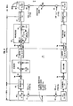
- FIG. 1 the invention is shown as applied to one direction of transmission for a communication path in, e.g., a cellular radiotelephone system.
- a path for the other direction would be essentially the same.
- One example of systems of the type in which the invention is illustratively useful is described at length in a collection of papers in the January 1979 Bell System Technical Journal. Accordingly, there are omitted from the drawings herein some details of the system which are not necessary for an understanding of the invention.
- the path illustrated in FIG. 1 includes a mobile facility, or terminal, 10, such as a vehicular unit which transports radio terminal equipment about the cells of the system service area.
- Terminal 10 is coupled through a radio link 11 to a fixed facility 12 which is in turn advantageously coupled to a zone office (not shown) of the public switched telephone network (PSTN).
- Fixed facility 12 advantageously includes a cell antenna site 13 with associated channel radio equipment and controls therefor, a mobile telecommunications switching office (MTSO) 16 and a signal processing facility receiving terminal 17 corresponding to the mobile terminal 10.
- MTSO mobile telecommunications switching office
- Analog speech signals are coupled through an anti-aliasing filter 14 which limits those signals to about a 300-3000 Hz band.
- An analog-to-digital converter 18 receives the filtered signals and schematically represents the establishment of an amplitude quantization range for the analog signal information. That range advantageously has a sufficient number Q of levels to represent speech signal variations with quantizing noise that is low enough to be of no significant annoyance to parties communicating over the illustrated path.
- the step size between levels is usually sufficient in relation to the magnitude of noise injected in a signal during transmission between terminals 10 and 17 that the noise can cause level errors of plural levels n; but n is such a small percent of the total number Q of levels that the error occurrence is not readily perceived by the typical human hearing function, hereinafter characterized simply as the human ear.
- the quantizing step size between levels is so related to the extent of noise that might be injected during transmission that transmission-noise-induced errors of a small number, at least one, of levels are in a range that is compatible with the error tolerating characteristic of the human ear. It has been found further that the ear can also tolerate errors of five percent or more in the number of levels in the quantizing range without introducing a significant degradation in perceived speech quality.
- the exact number is not critical. It has been found that 256 levels, which can be represented by 8-bit binary coded digital words, are convenient for digital signal processing, e.g., functions such as limiting, enciphering, and partial response encoding of signals, to achieve an advantageous compromise between maximizing information throughput rate and transmitted signal error rate.
- signals were quantized and digitally represented in a quantizing domain of many more levels than 256; but only the 256 levels (the 8 most significant bits of the digital representations) were used for certain of the illustrated functions, as previously noted, as an advantageous compromise between a desire for low quantizing noise and a need for a practical word bit length for those digital signal processing functions.
- Output of converter 18 is applied to a preliminary speech processing function block 19 which provides functions such as limiting, scaling, splitting, filtering, and decimating. These will be described in more detail in connection with FIG. 6, and they are provided for protection against noise for certain modulo arithmetic functions to be described and for developing in-phase and quadrature-phase versions of the signal to facilitate the filtering and other functions to be described.
- the resulting in-phase and quadrature versions of digitally represented analog sample amplitudes are applied through a sample masking and partial response encoding function block 20. Each of the masking and encoding functions involves a different modulo arithmetic operation.
- Yet another function block 21 provides one part, i.e.
- a suitable passband range e.g. 300-3000 Hz, which is characteristic of many circuits in the PSTN.
- the digitally represented masked sample amplitudes are thereafter converted to analog form by a digital-to-analog converter 22.
- At least the sample masking and the partial response functions take place in the same signal amplitude domain, that is, in the same signal quantizing range or at least in different compatible ranges.
- Compatible domains, or ranges are those in which the respective quantizing ranges each meets the foregoing specifications, as to low quantizing noise and as to compatibility with the error tolerating capability of the human ear, and signals can be translated between them by appropriate scaling.
- the cumulative partial response filtering (product of the square roots of transmit and receive parts of the filtering) is of the type which injects a predetermined controlled amount of intersymbol interference.
- Such filtering has heretofore been employed only for data transmission systems as to data symbols of a relatively few number of levels. Usually that number is at least an order of magnitude less than the number of levels that are needed for adequate representation of speech signal samples as above outlined. Also the step size with that smaller number of levels is usually so large that noise is unlikely to cause errors of even one level.
- intersymbol interference contemplated in those data systems is between data symbols whereas it is here contemplated in a sense which might be characterized as "intersample interference" where each sample is an analog value that is digitally represented, in the partial response filtering operation, by a plurality of discrete data symbols for convenience of processing.
- sample interference an analog value that is digitally represented, in the partial response filtering operation, by a plurality of discrete data symbols for convenience of processing.
- the transfer function of the partial response filtering function is determined largely by a frequency parameter represented by the frequency of occurrence of analog sample values which have a discrete representation.
- amplitude versus time diagram are shown analog wave representations of two time- adjacent impulses, such as data bits in a data system or speech samples in a voice system.
- These impulses are of the type that may have appeared at the input of the converter 22 in FIG. 1 if conventional Nyquist type filtering had been employed instead of the indicated partial response filtering.
- the solid line wave is the current impulse and the dashed wave is the one that preceded it in point of time.
- This type of filtering is designed theoretically to shape the impulses so that they each exhibit maximum amplitude in the center of a bit time and low amplitude so-called sidelobes on either time side which have zero crossings at the center points of adjacent bit intervals. That approach is taken to minimize intersymbol interference; but, as noted in the aforementioned Lender paper, the theoretical result is physically unrealizable. Consequently, practical applications have typically reduced the data transmission bit rate to achieve a reasonably low error rate.
- FIG. 3 amplitude versus time diagram are shown analog wave representations of two time- adjacent samples such as are applied to the input of the converter 22 in FIG. 1 when partial response filtering is employed.
- the solid line wave is the current one
- the dashed wave is the one that preceded it in point of time.
- the dotted wave is the sum of the current and prior waves and represents the type of waveshape that would be recovered at the output of block 30 (to be described) in fixed facility 12. It can be seen from that figure that the central, or main lobe, portions of the current and preceding impulses overlap by a known amount that is fixed for partial response functions by choosing partial response filtering passband in relation to the signal symbol rate (sample rate in the case of FIG. 1).
- ISI intersymbol interference
- FIG. 4 depicts a set of superimposed signal frequency bandwidth diagrams to illustrate the advantage of partial response processing in a bandwidth sense as newly applied to the speech transmission problem.
- any arbitrarily given uniform amplitude in a passband, impulse transmission rate, impulse error rate, and transmission channel bandwidth are assumed. It is also assumed that, in the illustrative application to sample masking, the baseband input signals before sample masking are band limited to a band such that after any intervening processing the resulting signal produced by digital-to-analog converter 22 will have a bandwidth approximately the same as that of the transmission channel, e.g., the allowable bandwidth of the radio link 11.
- the portion of the FIG. 4 diagram indicated by the bracket A represents a maximum limited band that must be imposed on input signals to prior systems employing Nyquist type filtering of the sample masked impulses that are to be applied to the radio link 11.
- the wider bandwidth portion indicated by the bracket B represents the wider limited band that must be imposed on input signals to systems of the type in FIG. 1 and employing partial response type filtering of the sample masked impulses to be applied to the same radio link 11.
- Portions A and B are typically passband signals here assumed to have a common lowest frequency such as 300 Hz. Portions A and B are double crosshatched to distinguish visually the premasking part of the diagram from the remainder.
- FIG. 4 portions indicated by brackets C and D represent the proportionately similar bandwidth expansion that normally results from sample masking for the input signals represented by portions A and B, respectively. Parts of C and D extending beyond the upper frequency end of B are single cross hatched. Finally, the FIG. 4 portion indicated by bracket E represents the ultimate bandwidth achieved for application of both the Nyquist and the Partial Response filtered signals to the common channel 11; and the part of E extending beyond D is uncrosshatched. It should be understood that although for convenience the portion E has been shown as having the same lowest frequency as the portions A through D, E is typically modulated up to be a passband signal of, e.g., 300-3000 Hz, for either A or B input in order to match typical telephone channel bandwidths in the PSTN.
- a passband signal e.g. 300-3000 Hz
- a system employing the heretofore typical Nyquist filtering must start with a band limited input signal of significantly narrower bandwidth, than is the case for a system using partial response filtering, in order to allow for the bandwidth expansions of both the sample masking operation and that of the Nyquist filtering to be done. It has been found that this difference in starting bandwidth is the margin between a receiving terminal signal that has sufficient bandwidth to represent an adequate frequency range of both male and female voices to be easy to listen to for extended periods and a receiving terminal signal that has insufficient bandwidth to represent those same voices without significant distortion, which renders the signals hard to listen to without undue fatigue for extended periods of time.
- FIG. 5 illustrates the discovery that the relation between quantizing step size and transmission noise required for data transmission is not necessary for analog speech sample transmission because of the aforementioned quantizing level detection error tolerance capability of the human hearing function, i.e., the so-called human ear.
- a randomly varying analog signal wave segment 37 representing transmission noise typically injected into a transmitted signal during transmission through a medium such as the FIG. 1 radio link 11.
- a pair of solid horizontal lines 38 represent a minimum binary coded data signal quantizing step size required to enable transmitted signal reception with a reasonably low error rate.
- the dashed lines 39 represent a minimum, though not critical, analog speech sample signal quantizing step size for enabling transmitted signal reception for good quality speech recovery.
- quantizing step size for speech can be made small enough to reduce quantizing noise to reasonable levels with sufficient resolution for good speech reproduction even though that small step size is much less than the expected transmission noise amplitude. That is, the human ear does not readily perceive level errors such as can be produced by noise of the indicated relative magnitude.
- an equalization training signal generator 15 provides a signal for training an equalization function in terminal 17. Output of generator 15 is switchably substituted for output of block 21 at appropriate times in the course of system operation, as is well known.
- a timing unit 23 in FIG. 1 produces various clock signals employed for the function blocks in the remainder of the terminal 10.
- the unit provides clock to a generator 26 of tones for, e.g., pilot tones employed in a single sideband system of the sort contemplated in connection with the single sideband receiver of the U. S. patent 4,403,348 of K. W. Leland and N. R. Sollenberger.
- Such tones can also be utilized for enciphering function countdown handshake between terminals and for other synchronizing functions, as is known in the art.
- the output of generator 26 is, in a digitally implemented embodiment, injected into the signal path, e.g., by arithmetic adding of time coincident sample values, at the input to converter 22.
- the tones are advantageously generated digitally, e.g., by known digital signal processing operations; and the resulting tone sample values can be here injected by adding digitally represented sample amplitudes.
- the resulting digitally represented speech and tone sample sums are converted to analog by converter 22 and applied via a sample smoothing filter 24 and appropriate transmitter radio frequency circuits, i.e. cellular audio processing and modulation circuit 25, to the radio link 11.
- Radio signals received at the cell site 13 are restored to their passband position, e.g., 300-3000 Hz. Those signals are then passed on a voice signal trunk used for the particular radio channel employed to the MTSO 16 where they are switched to a wire path, including terminal 17 for recovery of clear speech signals to be forwarded to the PSTN zone office.
- Terminal 17 is advantageously located on the zone office side of the MTSO so one need not deal with enciphering key changes when performing handoff.
- the receiving terminal 17 functions are in many respects essentially the inverse of those in the mobile terminal 10.
- Received analog samples are coupled through an anti-aliasing filter 34 and again converted to digital format by an analog-to-digital converter 27.
- Tone samples are extracted for detection by digital filtering functions in tone detectors 28.
- Output of those detectors is applied to a timing unit 29 which produces the various clock signals required for the functions of terminal 17.
- Output of converter 27 is also applied to a quadrature demodulator function block 30, which develops in-phase and quadrature phase versions of the signal samples, applies the remaining square root portion of the partial response filtering, and performs decimation prior to application of the signals to an equalizer function block 31. That block is operative for equalization training at appropriate times in system operation, e.g., when the terminal is started up for the incoming message. Otherwise, block 31 equalizes signals which are passed on to a partial response decoding and sample unmasking function block 32.
- Equalized outputs of block 31 are in block 32 unmasked by subtraction of the pseudorandom sample sequence used at terminal 10 and partial response decoded, both being modulo-Q operations.
- the deciphered speech samples are passed on to a speech deprocessing function block 33 where limiting, inverse scaling, interpolation, and filtering take place.
- the clear speech samples in digital form are restored to analog form by another digital-to-analog converter 36 prior to being coupled through a filter 40 for transmission to the local zone office in the public switched telephone networks (PSTN).
- Filter 40 is a low pass filter with cutoff frequency between the upper edge of the voice band and the sample rate for integrating the samples to restore the speech signal information.
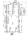
- FIG. 6 shows additional detail of the operations of the various functional blocks in the transmitter terminal 10 depicted in FIG. 1. Both analog and digital techniques are known in the art for implementing each of the circuit blocks shown in FIG. 6 in isolation, and such block details comprise no part of the present invention.
- the input to the speech processing function 19 in FIG. 6 is the digital form of analog speech samples provided from converter 18 in FIG. 1. Signal energy in the 300-2800 Hz baseband, corresponding to the band B in FIG. 4, is presented illustratively in an 8 kiloHertz, Q-level quantized sample stream. The sample amplitudes are in a range + y volts.
- Signal energy is split into two paths in which it is applied to modulators 41 and 42 for multiplying with sin cult and cos w I t signals, illustratively at 1550 Hz, to create the usual in-phase and quadrature-phase signals for convenience of further processing.
- Local oscillation sources for the modulators 41 and 42, and for other modulators and pulse sources to be mentioned, are advantageously a common oscillator in timing unit 23, with outputs properly phased, to assure coordinated operation of such sources within the transmitter. Operation of that oscillator is further coordinated with corresponding circuit elements in the receiving terminal by virtue of transmission of outputs of tone generator 26, as previously mentioned. Since further processing in these two in-phase and quadrature-phase paths is identical up to the point of later quadrature modulation to place the signals in a proper passband, only one path will be described.
- Output products from modulator 41 are low pass filtered in a filter 43 to confine further processing to the baseband product in the illustrative band 0-1250 Hz.
- a minimum sampling rate of 2500 Hz is required. Accordingly, the output of filter 42 is applied to a decimating function circuit 49 wherein only every third sample in the normal signal sequence is selected for use in the processing operations which follow. Decimating the 8 kHz sampled signal by three is easy to do and yields a 2667 Hz sampling rate. That new low rate also reduces the complexity of the digital signal processing to follow, and it makes the subsequent problem of transmitting masked sample information over a channel of limited bandwidth tractable.
- Output of decimating circuit 49 is applied through a multiplier 51, to be described, to one input of an amplitude scaling multiplier 46 which brings the received sampled signals into a range for efficient use of the available part of the quantizing range.
- the total range of levels is reduced by some number, X, of levels at each of the low and high ends of the range to leave an effective signal range of Q-2X levels.
- X is chosen to be about 28 levels to be sure that no noise-induced wrap-around can occur.
- Multiplier 46 performs the necessary scaling to bring the + y volt signal range into the Q-2X level range and receives both the output of multiplier 51 and a multiplier factor (Q-2X)/2Y.
- the centered signals are then amplitude limited to the range from X to Q-X levels in a limiter 48 to remove any extraordinary excursions that may have been present in the quantized received signals and persisted through the mentioned scaling and level shifting functions.
- Output from the limiting circuit 48 in the speech processing function 19 is applied to one input of an adder 50 for sample masking the speech samples.
- Adder 50 is operated for modulo operation, as is known in the art for sample masking, and here the operation is modulo Q.
- a random number Rn drawn from an enciphering sequence having values which are mutually independent and uniformly distributed over the desired coding interval Q, i.e., illustratively the same amplitude domain as that of the samples being masked.
- the sum An is taken modulo-Q so that
- the result An of this process is a sequence of random variables, the elements of which are uniformly distributed over the range Q, provided Q > Maximum Magnitude of Sn, and have amplitudes statistically independent of all other element values.
- Forming the enciphered sequences in the foregoing manner from the sampled version of the signal permits a secure waveform to be produced for transmission.
- the random number sequence used in the masking process is advantageously derived through use of the well known DES algorithm approved by the National Bureau of Standards.
- Rn is employed for the random sequences of both the in-phase and quadrature-phase branches in FIG. 6, the sequences used in the two branches are advantageously different, mutually independent sequences. The same is true of the sequences Rn in the receiver of FIG. 7.
- sample masking An interesting property of sample masking is that when low level unenciphered speech signals, e.g., from cross talk originating in the PSTN, are superimposed on enciphered speech signals in the receiving terminal, the low level speech will appear after deciphering as intelligible cross talk superimposed on the desired deciphered component. Cross talk of this nature will tend to give the false impression to the user of the enciphered channel that the channel is not secure. In applications where such crosstalk is a problem, this residual intelligibility of crosstalk is advantageously eliminated by multiplying speech signal samples prior to sample masking by a pseudorandom sequence Br of positive and negative unity gain functions in the multiplier 51. These effects are removed in the receiver after the deciphering process. Since the unenciphered crosstalk will not contain this pseudorandom multiplication, the removal of these factors from the desired signal in the receiver will also apply them to the crosstalk. This operation will render the crosstalk unintelligible.
- the masked samples are next applied to a partial response precoding circuit 52. There the samples are coupled through another modulo-Q adder wherein there is subtracted an impulse from the most recent prior sample time as represented by the T-delay circuit 56 coupled between the output and second input of adder 53.
- T is the duration of a sample interval in the decimated sample sequence and is the reciprocal of the decimated sequence sample rate. It is, however, emphasized here that this precoding operation operates, as indicated by the T-delay, on the basis of the decimated sequence sample interval or rate rather than on the bit interval of the digital data bits used to represent the sample magnitude in the illustrative digital processing implementation of the sample masking, partial response, and associated signal processing.
- a subtractor 55 subtracts a value corresponding to Q/2 levels from the output of adder 53 to remove the offset imposed by adder 47 and restore the bipolar characteristic of the signal.
- Output from adder 53 is also applied to an interpolating circuit 57 wherein each masked and precoded sample is interleaved with two zero-amplitude samples to accomplish a one-to-three interpolation, the inverse of the decimation in circuit 49, and thereby restore the sample rate to that at the input of speech processing circuit 19.
- the interpolated sample sequence is then coupled through a square root partial response filter 58 to an input of a modulator 59.
- Filter 58 has a square root of cosine type of amplitude characteristic as indicated by the small diagram of its frequency response, or transfer function, in FIG. 6.
- the filter has a cutoff frequency substantially less than the sample rate in the precoding circuit 52.
- that cutoff is at half of the decimated sample recurrence frequency, i.e. illustratively 1333 Hz, as indicated by 1/2T in the diagram, where T is the period of the decimated recurrence frequency, i.e. illustratively 2667 Hz.
- the result of such filtering is to incorporate a fixed, i.e. controlled, amount of intersymbol interference, again wherein the symbols under consideration are the sample amplitudes rather than the individual bits of a digitally represented value of that amplitude.
- Filtered signals in the in-phase and quadrature-phase paths of terminal 10 are applied to an input.of each of the modulator 59 and another modulator 60.
- Those modulators also receive local oscillator signals si n W2t and cos w 2 t for shifting the signals in the two paths to the passband position, i.e. 300-3000 Hz, of the channel to be used for transmission. Outputs of the modulators are combined in an adder 54 to form the sample masked analog sample stream for application to the converter 22 in FIG. 1.
- FIG. 7 is shown additional detail for the receiving terminal 17 at a level similar to that of the terminal 10.
- the quantized, sample masked, digitally encoded signals from analog-to-digital converter 27 in FIG. 1 are quadrature demodulated in modulators 61 and 62 in accordance with local oscillator signals at the same frequency, i.e. 1750 Hz, as was employed at modulators 59 and 60 in FIG. 6 mobile terminal 10.
- the resulting bandpass product at 0-1333 Hz is selected by a square root cosine filter 63 which also completes the intersymbol interference insertion effect of filter 58.
- Samples in the output of filter 63 have amplitudes in a range + Q.
- a three-to- one decimation is performed in a decimating circuit 66 since the full 8 kHz sample rate is not needed for the decoding and unmasking operations to be performed.
- the training equalizer 31 function of FIG. 1 is not shown in FIG. 7 for clarity.
- the decimated 2667 Hz sample rate signal is applied to a partial response decoding circuit 67.
- an adder 64 the value Q is added to all samples to convert them from a bipolar to a single sided form. In the latter form the signal is taken modulo Q in circuit 65. This removes the transmitter partial response coding effect as well as the intentionally inserted intersymbol interference and leaves discrete, masked samples.
- a modulo-Q subtractor 70 is removed in a modulo-Q subtractor 70 by subtracting the same pseudorandom pulse sequence Rn used in terminal 10.
- the clear samples are limited (after both modulo-Q arithmetic operations) by a limiter 72 to the same ⁇ X, Q - X ⁇ range employed in limiter 48, restored to their normal ground reference by subtractor 73 removing the Q/2 bias, and scaled back to the originally received sample amplitude range by multiplication in 76 by 2Y/(Q - 2X).
- the unmasked samples are, in a multiplier 71, multiplied by the reciprocal pseudorandom, plus and minus, unity gain sequence 1/Br to remove the crosstalk protection effect.
- An interpolating circuit 77 interleaves each sample with two zero-amplitude samples, in a manner that is the inverse of the decimation in circuit 66, to restore the original 8 kHz sample rate; and a low pass filter 78 limits the band of the 8 kHz samples to the 0-1250 Hz range so that they can be restored to the same band of 300-2800 Hz by use of the same frequency 1550 Hz signals employed in the transmitting terminal 10. That remodulation is performed by modulators 79 and 80, and their outputs are combined by an adder 75 prior to application to input of digital-to-analog converter 36 in FIG. 1.
Landscapes
- Engineering & Computer Science (AREA)
- Computer Networks & Wireless Communication (AREA)
- Signal Processing (AREA)
- Physics & Mathematics (AREA)
- Spectroscopy & Molecular Physics (AREA)
- Power Engineering (AREA)
- Transmission Systems Not Characterized By The Medium Used For Transmission (AREA)
- Compression, Expansion, Code Conversion, And Decoders (AREA)
- Digital Transmission Methods That Use Modulated Carrier Waves (AREA)
Applications Claiming Priority (2)
| Application Number | Priority Date | Filing Date | Title |
|---|---|---|---|
| US748192 | 1985-06-24 | ||
| US06/748,192 US4754481A (en) | 1985-06-24 | 1985-06-24 | Expanded partial response processing for analog signal enciphering and the like |
Publications (2)
| Publication Number | Publication Date |
|---|---|
| EP0206264A2 true EP0206264A2 (de) | 1986-12-30 |
| EP0206264A3 EP0206264A3 (de) | 1988-09-07 |
Family
ID=25008410
Family Applications (1)
| Application Number | Title | Priority Date | Filing Date |
|---|---|---|---|
| EP86108383A Withdrawn EP0206264A3 (de) | 1985-06-24 | 1986-06-19 | Ausgedehnte Partialresponsesignalverarbeitung zur Verschlüsselung von Analogsignalen oder Ähnlichem |
Country Status (4)
| Country | Link |
|---|---|
| US (1) | US4754481A (de) |
| EP (1) | EP0206264A3 (de) |
| JP (1) | JPS621334A (de) |
| CA (1) | CA1252237A (de) |
Cited By (1)
| Publication number | Priority date | Publication date | Assignee | Title |
|---|---|---|---|---|
| RU2204886C2 (ru) * | 2000-12-19 | 2003-05-20 | Военная академия Ракетных войск стратегического назначения им. Петра Великого | Способ шифрования с исправлением ошибок канала связи и устройство для его осуществления |
Families Citing this family (10)
| Publication number | Priority date | Publication date | Assignee | Title |
|---|---|---|---|---|
| US4870682A (en) * | 1987-02-25 | 1989-09-26 | Household Data Services (Hds) | Television scrambling system |
| SE465797B (sv) * | 1990-03-07 | 1991-10-28 | Ericsson Telefon Ab L M | Foerfarande att oeverfoera synkroniseringsinformation vid krypterad oeverfoering i ett mobilradiosystem |
| US5091942A (en) * | 1990-07-23 | 1992-02-25 | Ericsson Ge Mobile Communications Holding, Inc. | Authentication system for digital cellular communications |
| US5081679A (en) * | 1990-07-20 | 1992-01-14 | Ericsson Ge Mobile Communications Holding Inc. | Resynchronization of encryption systems upon handoff |
| US5237612A (en) * | 1991-03-29 | 1993-08-17 | Ericsson Ge Mobile Communications Inc. | Cellular verification and validation system |
| US5241598A (en) * | 1991-05-22 | 1993-08-31 | Ericsson Ge Mobile Communications, Inc. | Rolling key resynchronization in cellular verification and validation system |
| JPH05317021A (ja) * | 1992-05-26 | 1993-12-03 | Kobaade:Kk | 縦縞押出機 |
| US5742679A (en) * | 1996-08-19 | 1998-04-21 | Rockwell International Corporation | Optimized simultaneous audio and data transmission using QADM with phase randomization |
| US7640000B2 (en) * | 2005-12-10 | 2009-12-29 | Electronics And Telecommunications Research Institute | Apparatus and method for cancellation of partially overlapped crosstalk signals |
| US7982994B1 (en) * | 2010-05-12 | 2011-07-19 | Seagate Technology, Llc | Multi-level recording on shingled coherent magnetic media |
Family Cites Families (6)
| Publication number | Priority date | Publication date | Assignee | Title |
|---|---|---|---|---|
| US4283602A (en) * | 1966-06-03 | 1981-08-11 | International Telephone And Telegraph Corporation | Cryptographically secure communication system |
| JPS5224409A (en) * | 1975-08-20 | 1977-02-23 | Fujitsu Ltd | Partial response modulation system |
| IT1052696B (it) * | 1975-12-18 | 1981-07-20 | Cselt Centro Studi Lab Telecom | Procedimento e dispositivo numerico per la correzione adattativa della fase nella demodulazione coerente di segnali numerici |
| US4086435A (en) * | 1976-09-17 | 1978-04-25 | Biosystems Research Group Ii | Method of and means for scrambling and descrambling speech at audio frequencies |
| GB1592556A (en) * | 1976-10-28 | 1981-07-08 | Rixon | Quadrature-amplitude-modulation data transmission systems and transmitters |
| US4398062A (en) * | 1976-11-11 | 1983-08-09 | Harris Corporation | Apparatus for privacy transmission in system having bandwidth constraint |
-
1985
- 1985-06-24 US US06/748,192 patent/US4754481A/en not_active Expired - Lifetime
-
1986
- 1986-06-12 CA CA000511412A patent/CA1252237A/en not_active Expired
- 1986-06-19 EP EP86108383A patent/EP0206264A3/de not_active Withdrawn
- 1986-06-24 JP JP61146275A patent/JPS621334A/ja active Pending
Cited By (1)
| Publication number | Priority date | Publication date | Assignee | Title |
|---|---|---|---|---|
| RU2204886C2 (ru) * | 2000-12-19 | 2003-05-20 | Военная академия Ракетных войск стратегического назначения им. Петра Великого | Способ шифрования с исправлением ошибок канала связи и устройство для его осуществления |
Also Published As
| Publication number | Publication date |
|---|---|
| CA1252237A (en) | 1989-04-04 |
| EP0206264A3 (de) | 1988-09-07 |
| US4754481A (en) | 1988-06-28 |
| JPS621334A (ja) | 1987-01-07 |
Similar Documents
| Publication | Publication Date | Title |
|---|---|---|
| US4972474A (en) | Integer encryptor | |
| US4523311A (en) | Simultaneous transmission of speech and data over an analog channel | |
| KR100186803B1 (ko) | 악영향을 주는 간섭을 개선한 송.수신 | |
| US5025443A (en) | Digital data over voice communication | |
| US4720839A (en) | Efficiency data transmission technique | |
| US4754481A (en) | Expanded partial response processing for analog signal enciphering and the like | |
| US5778055A (en) | System for, and method of, transmitting and receiving through telephone lines signals representing data | |
| US6091781A (en) | Single sideband transmission of QPSK, QAM and other signals | |
| US4398062A (en) | Apparatus for privacy transmission in system having bandwidth constraint | |
| KR860002153B1 (ko) | 비화신호 송신시스템 | |
| US4712240A (en) | Transmission and reception of television broadcast in high-fidelity stereo audio | |
| US7801559B2 (en) | Methods and apparatus for baseband digital spectrum translation (BDST) | |
| US5500892A (en) | Echo canceller | |
| US5742679A (en) | Optimized simultaneous audio and data transmission using QADM with phase randomization | |
| US4837821A (en) | Signal transmission system having encoder/decoder without frame synchronization signal | |
| US7453951B2 (en) | System and method for the transmission of an audio or speech signal | |
| Kalet et al. | The capacity of PCM voiceband channels | |
| CA1178665A (en) | Method and apparatus for converting binary information into a high density single-side band signal | |
| JP4408446B2 (ja) | 低い信号対雑音比でqam信号を送信および受信する方法 | |
| RU2221284C2 (ru) | Способ передачи и приема закодированной речи | |
| Ehsani et al. | Fast Fourier transform speech scrambler | |
| Sreekanth | Digital microwave communication systems: with selected topics in mobile communications | |
| EP1295451A1 (de) | Vorrichtung und verfahren für übertragung mit hoher datenrate | |
| US4800576A (en) | Convolution data recovery circuit | |
| JP3274293B2 (ja) | 信号処理装置 |
Legal Events
| Date | Code | Title | Description |
|---|---|---|---|
| PUAI | Public reference made under article 153(3) epc to a published international application that has entered the european phase |
Free format text: ORIGINAL CODE: 0009012 |
|
| AK | Designated contracting states |
Kind code of ref document: A2 Designated state(s): DE FR GB IT SE |
|
| PUAL | Search report despatched |
Free format text: ORIGINAL CODE: 0009013 |
|
| AK | Designated contracting states |
Kind code of ref document: A3 Designated state(s): DE FR GB IT SE |
|
| 17P | Request for examination filed |
Effective date: 19890224 |
|
| 17Q | First examination report despatched |
Effective date: 19910528 |
|
| STAA | Information on the status of an ep patent application or granted ep patent |
Free format text: STATUS: THE APPLICATION HAS BEEN WITHDRAWN |
|
| 18W | Application withdrawn |
Withdrawal date: 19910828 |
|
| R18W | Application withdrawn (corrected) |
Effective date: 19910828 |
|
| RIN1 | Information on inventor provided before grant (corrected) |
Inventor name: FEGGELER, JOHN CHARLES |