EP0206338A2 - Lichtmodulator - Google Patents
Lichtmodulator Download PDFInfo
- Publication number
- EP0206338A2 EP0206338A2 EP86108709A EP86108709A EP0206338A2 EP 0206338 A2 EP0206338 A2 EP 0206338A2 EP 86108709 A EP86108709 A EP 86108709A EP 86108709 A EP86108709 A EP 86108709A EP 0206338 A2 EP0206338 A2 EP 0206338A2
- Authority
- EP
- European Patent Office
- Prior art keywords
- laser diode
- semiconductor laser
- light
- signal
- light modulator
- Prior art date
- Legal status (The legal status is an assumption and is not a legal conclusion. Google has not performed a legal analysis and makes no representation as to the accuracy of the status listed.)
- Withdrawn
Links
Images
Classifications
-
- H—ELECTRICITY
- H01—ELECTRIC ELEMENTS
- H01S—DEVICES USING THE PROCESS OF LIGHT AMPLIFICATION BY STIMULATED EMISSION OF RADIATION [LASER] TO AMPLIFY OR GENERATE LIGHT; DEVICES USING STIMULATED EMISSION OF ELECTROMAGNETIC RADIATION IN WAVE RANGES OTHER THAN OPTICAL
- H01S5/00—Semiconductor lasers
- H01S5/06—Arrangements for controlling the laser output parameters, e.g. by operating on the active medium
- H01S5/062—Arrangements for controlling the laser output parameters, e.g. by operating on the active medium by varying the potential of the electrodes
- H01S5/06209—Arrangements for controlling the laser output parameters, e.g. by operating on the active medium by varying the potential of the electrodes in single-section lasers
- H01S5/06213—Amplitude modulation
-
- H—ELECTRICITY
- H01—ELECTRIC ELEMENTS
- H01S—DEVICES USING THE PROCESS OF LIGHT AMPLIFICATION BY STIMULATED EMISSION OF RADIATION [LASER] TO AMPLIFY OR GENERATE LIGHT; DEVICES USING STIMULATED EMISSION OF ELECTROMAGNETIC RADIATION IN WAVE RANGES OTHER THAN OPTICAL
- H01S5/00—Semiconductor lasers
- H01S5/06—Arrangements for controlling the laser output parameters, e.g. by operating on the active medium
- H01S5/062—Arrangements for controlling the laser output parameters, e.g. by operating on the active medium by varying the potential of the electrodes
- H01S5/06223—Arrangements for controlling the laser output parameters, e.g. by operating on the active medium by varying the potential of the electrodes using delayed or positive feedback
-
- H—ELECTRICITY
- H01—ELECTRIC ELEMENTS
- H01S—DEVICES USING THE PROCESS OF LIGHT AMPLIFICATION BY STIMULATED EMISSION OF RADIATION [LASER] TO AMPLIFY OR GENERATE LIGHT; DEVICES USING STIMULATED EMISSION OF ELECTROMAGNETIC RADIATION IN WAVE RANGES OTHER THAN OPTICAL
- H01S5/00—Semiconductor lasers
- H01S5/06—Arrangements for controlling the laser output parameters, e.g. by operating on the active medium
- H01S5/065—Mode locking; Mode suppression; Mode selection ; Self pulsating
- H01S5/0658—Self-pulsating
Definitions
- the present invention relates to a light modulator and, more particularly, to a modulator using a semiconductor laser diode.
- optical transmission system It is known in the art to use semiconductor diodes for the transmission systems, such as video signal transmission systems. Such a transmission system is generally referred to as an optical transmission system. Although the optical transmission system has advantages in wide modulation bandwidth and high coupling efficiency, it also has the following problems.
- speckles in optical fibers generated by the interference among propagating modes in the optical fibers due to the change in the coupling coefficient at junctions of optical fibers, adversely affect the linearity of the signal propagation, resulting in the generation of noise signals which are generally called speckle noise.
- Another problem is the laser diode linearity deterioration caused by the-light reflected back to the laser from the optical fiber at the coupler, resulting in the generation of unwanted reflection noise signals.
- the signal to be transmitted is superimposed by a high frequency carrier (about 1 GHz).
- a high frequency carrier about 1 GHz.
- the laser diode performs a multilongitudinal mode oscillation, thereby widening the oscillation spectral width. This results in the chirping, i.e., the undesirable variation of wavelength of the laser generated from the laser diode, and also results in the reduction of the coherence of the laser.
- This is further disclosed in an article "Speckle Noise Reduction in Fiber Optic Analog Video Transmission Using Semiconductor Laser Diodes" by Sato et al presented in IEEE TRANSACTIONS ON COMMUNICATIONS, Vol. COM-29, No. 7, July 1981, pages 1017-1024.
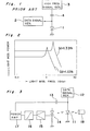
- FIG. 1 An example of a prior art light modulator is shown in Fig. 1 in which a data signal generator 2 generates a data signal to be modulated, such as a video signal.
- the data signal from generator 2 is superimposed on a high frequency carrier signal provided from high frequency signal generator 3 through capacitor 4.
- the superimposed signal is applied to semiconductor laser diode 1 at which the light modulation is carried out.
- the prior art light modulator has the following disadvantages. Since the semiconductor laser diode has a relatively large value of coupling capacitance, the total capacitance of the light modulator takes a large value, resulting in high power of high frequency signal on which the data signal is superimposed. Therefore, it is necessary to prepare a high frequency signal generator 3 which is capable of producing a high power output, resulting in a high manufacturing cost. Also, such a high power output accompanies unwanted electromagnetic wave emission which enhances the noise signal.
- the present invention has been developed with a view to substantially solving the above described disadvantages and has for its essential object to provide an improved light modulator which can operate at a low power and can be manufactured at low cost.
- a light modulator for modulating data signal to high frequency light signal comprises a semiconductor laser diode having an input for receiving the data signal and an output for producing laser, a light detector for receiving the laser and producing an electric signal representing the laser, and an electric passage between the light detector and the input of the semiconductor laser diode so as to define a positive feedback circuit for feeding the output of the semiconductor laser diode to the input of the same, whereby an oscillation at a resonance frequency is effected in the semiconductor laser diode to generate a light modulated high frequency laser signal from the semiconductor laser diode.
- the output characteristic of a semiconductor laser diode used for the light modulation varies with respect to the driving current Id.
- the resonance frequency Fr exists near and on the low frequency side of the cutoff frequency of the semiconductor laser diode, and it can be given by the following equation (1) wherein T p is a photon lifetime and T s is a carrier lifetime.
- the light modulator If the light modulation is carried out at the resonance frequency, a high output power can be obtained with a small driving current. Therefore, the analog form data signal, which has been DC biased, may be used as the driving current Id for the light modulation. In this case, the resonance frequency Fr varies with respect to the change of the data signal. If the semiconductor laser diode can be driven at the resonance frequency Fr by some means, it is possible to carry out the light modulation at the minimum power consumption.
- the light modulator according to the present invention provides such means as described below.
- the light modulator comprises a semiconductor laser diode 11 which is connected to a data signal generator 12 for generating analog data signal, such as a video signal, having a frequency ranging from 0 to about 500 MHz.
- a data signal generator 12 for generating analog data signal, such as a video signal, having a frequency ranging from 0 to about 500 MHz.
- Semiconductor laser diode 11 produces laser beam in the opposite directions, one is directed to a light detector 14 and the other is directed to a light transmission line, such as an optical fiber 18 through a suitable converging lens (not shown).
- the output of light detector 14 is connected to a preamplifier 15 and further to a high pass filter 16 having a pass band of 800 MHz to 10 GHz.
- the output of high pass filter 16 is connected to a power amplifier 17 which is in turn connected through a capacitor 13 to the input of semiconductor laser diode 11, thereby defining a positive feedback circuit for the high frequency signal produced from the semiconductor laser diode driven under the multilongitudinal mode.
- the laser produced from laser diode 11 is detected by light detector 14 which then produces an electric signal corresponding to the laser beam signal.
- the electric signal from detector 14 is amplified by preamplifier 15 and is filtered at high pass filter 16 so as to cutoff the low frequency components.
- the filtered high frequency signal is amplified at amplifier 17 and is fed back through capacitor 13 to semiconductor laser diode 11. In this manner, the high frequency signal circulates in the positive feedback circuit so that the semiconductor laser diode 11 is applied with a high frequency driving current which effects the relaxation oscillation in the laser diode at resonance frequency. Therefore, semiconductor laser diode 11 makes a stable oscillation under the multilongitudinal mode with a minimum necessary power.
- the spectral width of oscillation is broadened and, at the same time, the laser coherence is reduced. Furthermore, the noise signals, particularly the reflection noise signals caused by the reflected light may be effectively reduced, thereby producing light modulated signal having very low S/N ratio.
- the light modulation can be carried out in the semiconductor laser diode without employing any high frequency signal generator, separately. Therefore, the light modulator according to the present invention can be manufactured at low cost. Furthermore, since the oscillation can be done with a very low power, the light modulator can be operated with a simple power source.
Landscapes
- Physics & Mathematics (AREA)
- Condensed Matter Physics & Semiconductors (AREA)
- General Physics & Mathematics (AREA)
- Electromagnetism (AREA)
- Optics & Photonics (AREA)
- Semiconductor Lasers (AREA)
- Optical Communication System (AREA)
- Optical Head (AREA)
Applications Claiming Priority (2)
| Application Number | Priority Date | Filing Date | Title |
|---|---|---|---|
| JP60143687A JPS623534A (ja) | 1985-06-28 | 1985-06-28 | 光変調装置 |
| JP143687/85 | 1985-06-28 |
Publications (2)
| Publication Number | Publication Date |
|---|---|
| EP0206338A2 true EP0206338A2 (de) | 1986-12-30 |
| EP0206338A3 EP0206338A3 (de) | 1988-08-31 |
Family
ID=15344615
Family Applications (1)
| Application Number | Title | Priority Date | Filing Date |
|---|---|---|---|
| EP86108709A Withdrawn EP0206338A3 (de) | 1985-06-28 | 1986-06-26 | Lichtmodulator |
Country Status (3)
| Country | Link |
|---|---|
| US (1) | US4819240A (de) |
| EP (1) | EP0206338A3 (de) |
| JP (1) | JPS623534A (de) |
Cited By (2)
| Publication number | Priority date | Publication date | Assignee | Title |
|---|---|---|---|---|
| EP0492480A3 (en) * | 1990-12-21 | 1992-07-29 | Cselt Centro Studi E Laboratori Telecomunicazioni S.P.A. | A system for the generation of modulated optical signals |
| EP0643879A4 (de) * | 1992-06-01 | 1995-09-06 | Finisar Corp | Verfahren und gerät zur anregung einer laserdiode in einem faseroptischen sender. |
Families Citing this family (6)
| Publication number | Priority date | Publication date | Assignee | Title |
|---|---|---|---|---|
| US4872173A (en) * | 1988-09-02 | 1989-10-03 | Northern Telecom Limited | Method and apparatus for stabilizing the spectral characteristics of a semiconductor laser diode |
| JPH03113736A (ja) * | 1989-09-22 | 1991-05-15 | Olympus Optical Co Ltd | 半導体レーザの駆動装置 |
| US5184189A (en) * | 1989-09-26 | 1993-02-02 | The United States Of Americas As Represented By The United States Department Of Energy | Non-intrusive beam power monitor for high power pulsed or continuous wave lasers |
| US4989212A (en) * | 1990-04-09 | 1991-01-29 | Trw, Inc. | Laser diode phase modulation technique |
| JP3553222B2 (ja) * | 1995-09-20 | 2004-08-11 | 三菱電機株式会社 | 光変調器モジュール |
| DE19607880C2 (de) * | 1996-03-01 | 1998-01-22 | Agfa Gevaert Ag | Verfahren und Schaltung zum Betrieb einer Laserdiode |
Family Cites Families (9)
| Publication number | Priority date | Publication date | Assignee | Title |
|---|---|---|---|---|
| DE508999C (de) * | 1930-10-03 | Schwarzwaldwerke Lanz G M B H | Milchschleuder | |
| CH503394A (de) * | 1969-02-06 | 1971-02-15 | Inst Angewandte Physik | Verfahren zur Modulation eines Laserstrahles |
| US3617932A (en) * | 1969-06-16 | 1971-11-02 | Bell Telephone Labor Inc | Method for pulse-width-modulating semiconductor lasers |
| CH508999A (de) * | 1970-09-26 | 1971-06-15 | Guekos Georg | Anordnung zur Erzeugung rauscharmer Laser-Strahlung von elektrisch angeregten Festkörper-Lasern |
| CA1101923A (en) * | 1978-09-21 | 1981-05-26 | Joseph Straus | Injection laser operation |
| JPS59129948A (ja) * | 1983-01-14 | 1984-07-26 | Hitachi Ltd | 光情報処理装置 |
| JPS6035344A (ja) * | 1983-08-08 | 1985-02-23 | Hitachi Tobu Semiconductor Ltd | 発光装置およびこれを用いた光学的信号処理装置 |
| JPS6064485A (ja) * | 1983-09-20 | 1985-04-13 | Matsushita Electric Ind Co Ltd | 半導体レ−ザの出力安定装置 |
| JPS6065590A (ja) * | 1983-09-20 | 1985-04-15 | Mitsubishi Electric Corp | 半導体レ−ザ装置 |
-
1985
- 1985-06-28 JP JP60143687A patent/JPS623534A/ja active Granted
-
1986
- 1986-06-26 EP EP86108709A patent/EP0206338A3/de not_active Withdrawn
-
1988
- 1988-04-07 US US07/180,637 patent/US4819240A/en not_active Expired - Lifetime
Cited By (3)
| Publication number | Priority date | Publication date | Assignee | Title |
|---|---|---|---|---|
| EP0492480A3 (en) * | 1990-12-21 | 1992-07-29 | Cselt Centro Studi E Laboratori Telecomunicazioni S.P.A. | A system for the generation of modulated optical signals |
| US5197075A (en) * | 1990-12-21 | 1993-03-23 | Cselt - Centro Studi E Laboratori Telecomunicazioni S.P.A. | Apparatus and method for the generation of modulated optical signals using a semiconductor laser |
| EP0643879A4 (de) * | 1992-06-01 | 1995-09-06 | Finisar Corp | Verfahren und gerät zur anregung einer laserdiode in einem faseroptischen sender. |
Also Published As
| Publication number | Publication date |
|---|---|
| JPS623534A (ja) | 1987-01-09 |
| US4819240A (en) | 1989-04-04 |
| JPH0342025B2 (de) | 1991-06-25 |
| EP0206338A3 (de) | 1988-08-31 |
Similar Documents
| Publication | Publication Date | Title |
|---|---|---|
| US5781327A (en) | Optically efficient high dynamic range electro-optic modulator | |
| US4561119A (en) | Optical frequency modulation system | |
| US6359716B1 (en) | All-optical analog FM optical receiver | |
| CA2072815C (en) | Narrow band incoherent optical carrier generator | |
| Yamamoto | Characteristics of AlGaAs Fabry-Perot cavity type laser amplifiers | |
| RU2153215C1 (ru) | Способ и устройство стабилизации полупроводникового лазера | |
| EP0494979B1 (de) | Oszillator | |
| EP0247834A1 (de) | Optischer Signalregenerator | |
| JPS62116030A (ja) | コヒ−レントな光波のトランスミツタ | |
| US4819240A (en) | Light modulator | |
| CA2138961A1 (en) | Optical source for communications system | |
| US5025487A (en) | System for transmitting information on interferometrically generated optical carriers | |
| USH1702H (en) | Wideband fiber-optic signal processor | |
| US4357713A (en) | Method and apparatus for reduction of modal noise in fiber optic systems | |
| EP0559102B1 (de) | Frequenzumsetzer | |
| US6904100B1 (en) | Pulse controlled phase modulator | |
| US6266351B1 (en) | Generator for producing a high-frequency, low-noise signal | |
| JP3520727B2 (ja) | 電波発生器 | |
| CN114415148B (zh) | 集目标探测和频率测量的一体化微波光子雷达系统 | |
| JPH0218526A (ja) | 光伝送方式と光伝送装置 | |
| JP3008677B2 (ja) | 光送信装置 | |
| US5923687A (en) | Bandwidth enhancement and broadband noise reduction in injection-locked semiconductor lasers | |
| JPS5961822A (ja) | ホモダイン検波型光受光装置 | |
| EP0189295A2 (de) | Modulationsverfahren für einen Halbleiterlaser | |
| JPS6160622B2 (de) |
Legal Events
| Date | Code | Title | Description |
|---|---|---|---|
| PUAI | Public reference made under article 153(3) epc to a published international application that has entered the european phase |
Free format text: ORIGINAL CODE: 0009012 |
|
| AK | Designated contracting states |
Kind code of ref document: A2 Designated state(s): DE GB NL |
|
| 17P | Request for examination filed |
Effective date: 19861231 |
|
| PUAL | Search report despatched |
Free format text: ORIGINAL CODE: 0009013 |
|
| AK | Designated contracting states |
Kind code of ref document: A3 Designated state(s): DE GB NL |
|
| 17Q | First examination report despatched |
Effective date: 19910128 |
|
| STAA | Information on the status of an ep patent application or granted ep patent |
Free format text: STATUS: THE APPLICATION HAS BEEN WITHDRAWN |
|
| 18W | Application withdrawn |
Withdrawal date: 19920811 |
|
| RIN1 | Information on inventor provided before grant (corrected) |
Inventor name: YOSHIDA, TOSHIHIKOAKATSUKI-RYO 301 Inventor name: MATSUI, SADAYOSHI Inventor name: TAKIGUCHI, HARUHISA Inventor name: KANEIWA, SHINJIKYOBATA-MANSHON 101 |