EP0206408A1 - Digitales Übertragungssystem höherer Ordnung welches einen Multiplexer und einen Demultiplexer enthält - Google Patents
Digitales Übertragungssystem höherer Ordnung welches einen Multiplexer und einen Demultiplexer enthält Download PDFInfo
- Publication number
- EP0206408A1 EP0206408A1 EP19860201032 EP86201032A EP0206408A1 EP 0206408 A1 EP0206408 A1 EP 0206408A1 EP 19860201032 EP19860201032 EP 19860201032 EP 86201032 A EP86201032 A EP 86201032A EP 0206408 A1 EP0206408 A1 EP 0206408A1
- Authority
- EP
- European Patent Office
- Prior art keywords
- demultiplexer
- multiplexer
- digital signal
- digital
- outputs
- Prior art date
- Legal status (The legal status is an assumption and is not a legal conclusion. Google has not performed a legal analysis and makes no representation as to the accuracy of the status listed.)
- Granted
Links
- 230000005540 biological transmission Effects 0.000 title claims abstract description 23
- 239000011159 matrix material Substances 0.000 claims description 27
- 239000002131 composite material Substances 0.000 claims description 7
- 230000001360 synchronised effect Effects 0.000 claims description 3
- 238000012545 processing Methods 0.000 abstract description 3
- 238000012544 monitoring process Methods 0.000 abstract description 2
- 238000010586 diagram Methods 0.000 description 10
- 238000000034 method Methods 0.000 description 8
- 230000001629 suppression Effects 0.000 description 2
- 238000013519 translation Methods 0.000 description 2
- 230000000903 blocking effect Effects 0.000 description 1
- 230000008878 coupling Effects 0.000 description 1
- 238000010168 coupling process Methods 0.000 description 1
- 238000005859 coupling reaction Methods 0.000 description 1
- 238000013461 design Methods 0.000 description 1
- 238000001514 detection method Methods 0.000 description 1
- 230000010354 integration Effects 0.000 description 1
- 230000003287 optical effect Effects 0.000 description 1
- 239000013307 optical fiber Substances 0.000 description 1
- 230000002035 prolonged effect Effects 0.000 description 1
- 230000001172 regenerating effect Effects 0.000 description 1
- 238000012552 review Methods 0.000 description 1
Images

Classifications
-
- H—ELECTRICITY
- H04—ELECTRIC COMMUNICATION TECHNIQUE
- H04J—MULTIPLEX COMMUNICATION
- H04J3/00—Time-division multiplex systems
- H04J3/02—Details
- H04J3/04—Distributors combined with modulators or demodulators
- H04J3/047—Distributors with transistors or integrated circuits
-
- H—ELECTRICITY
- H04—ELECTRIC COMMUNICATION TECHNIQUE
- H04J—MULTIPLEX COMMUNICATION
- H04J3/00—Time-division multiplex systems
- H04J3/02—Details
- H04J3/06—Synchronising arrangements
- H04J3/0602—Systems characterised by the synchronising information used
- H04J3/0605—Special codes used as synchronising signal
Definitions
- the invention relates to a higher order digital transmission system including a digital multiplexer having N parallel inputs, and a digital demultiplexer having N parallel outputs for transmitting N mutually synchronized digital signal streams through a common digital path between said multiplexer and demultiplexer, where N)2 and the multiplexer being arranged for cyclically and symbol-sequential interleaving the N digital signal streams to form a composite digital signal stream, the transmission system further including at least a block coding arrangement and a block decoding arrangement.
- N incoming signal streams are combined to form one outgoing signal stream, whilst the opposite operation occurs in the demultiplexer.
- Multiplexing the incoming signal streams is effected by means of interleaving, which implies that a bit from a binary signal stream 1 is followed by a bit from a binary signal stream 2 etc.
- the resultant outgoing signal stream has a digital rate which is higher than or equal to N times the digital rate of the N incoming signal streams. This is caused by the fact that the outgoing signal stream requires its own frame word and a few service bits, which are added to the outgoing signal stream. Provisions are also taken to compensate for frequency differences between the tributary signal streams and the multiplex clock.
- This digital path may, for example, be constituted by symmetrical or coaxial cables, optical fibres or the air.
- One of the objects usually is the suppression of the direct current component, which permits of the use of alternating current couplings in the transmission system, and direct current supply of the regenerators from the transmission system via the transmission cable being possible.
- Another object often is to increase the pulse density of the digital signal to be conveyed, or to ensure a minimum pulse density such that recovering a clock signal, required in regenerative circuits, is possible.
- a series/parallel converter which devides the bit stream applied to its input in consecutive blocks of a predetermined number of bits n is provided at the input of the encoding arrangement.
- a block of n bits is thereafter converted with the aid of the translation code matrix into a new block of m symbols in accordance with a specific instruction.
- Blocks of m symbols are reconverted at the output of the encoding arrangement with the aid of a parallel/series converter into a bit stream which is conveyed to the receiver portion of the digital transmission system via the digital path (cable, optical fibre).
- bit stream applied there is subjected to a reverse process with the aid of the decoding arrangement.
- Examplesof an encoding arrangement and a decoding arrangement are described in, for example, Proceedings 17th International Scientific Congress on Electronics, Rome, 16-18 March 1970, pages 275-283.
- a higher order digital multiplex system of the above-defined type is disclosed in, for example, C.C.I.T.T. Recommendation G922.
- the frame structure of a multiplex system having 4 tributary signal streams of 140 Mbit/s each is described.
- a frame has a length of 2688 bits and comprises: a 12-bit frame synchronizing word; 4 service bits; 4 5-bit justification control words, one for each tributary signal stream; 4 justifiable bits, one for each tributary signal stream and 2648 time slots for the information from the four tributary signal streams.
- the block encoding arrangement is arranged subsequent to the multiplexer and the block encoding arrangement precedes the demultiplexer.
- the invention has for its object to provide a novel concept of a higher order digital transmission system of the type defined in the preamble, which solves the above-mentioned problems.
- the invention is characterized, in that each of the N digital signal streams are applied to one of the N parallel inputs of the multiplexer via a block encoding arrangement, that the N digital signal streams are entered synchronously under the control of a common clock signal into the N block encoding arrangements and, in the respective block encoding arrangements, are provided with a word synchronizing characteristic, that the parallel outputs of the demultiplexer are each connected to the input of a block decoding arrangement, that the signals applied to the parallel outputs of the demultiplexer are entered into the respective block decoding arrangements under the control of the clock signal recovered from the composite digital signal, that the outputs of the block decoding arrangements are each connected to an input of a matrix switch having as many outputs as there are inputs, that in a phase comparator arrangement the word synchronizing characteristics of the block decoding arrangements are compared with each other, whereafter as a function of the phase difference measured between said word synchronizing characteristics each input of the matrix switch is through-connected to an output, such that the original digital signal streams become available again in
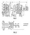
- I is the transmitter portion of the system and II the receiver portion of the system.
- the transmitter portion I comprises the block encoding arrangement 1, 2, 3 and 4, the multiplexer 6, the divider 5 and the multipliers 7 and 9.
- the receiver portion II comprises the block decoding arrangements 12, 13, 14 and 15, the demultiplexer 11, the phase comparator 16, the divider 19, the clock regenerator 17 and the switching matrix 18.
- the write clock inputs of the block encoding arrangements 1 to 4 are together connected to the clock input 8 of the transmitter portion I of the transmission system via the line 70.
- the clock input 8 is connected via a divide-by-5-divider and the line 71 to the clock inputs of the block encoding arrangements 1 to 4, which from the four digital signal streams A to D form D 5-bit blocks, and also to the input of a multiply-by-6 multiplier 9.
- the output of the multiply-by-6 multiplier 9 is connected via the line 72 to the write clock inputs of the multiplexer 6 and also via a multiply-by-4 multiplier to the read clock output of the multiplexer 6.
- Each of the signal outputs 60 to 63 of the block encoding arrangements is connected to a signal input of the multiplexer 6.
- the signal output 65 of the multiplexer 6 is connected via a digital path 10 to the input 66 of the receiver portion II of the transmission system.
- the input 66 is connected to the signal input of the demultiplexer 11 and also to the input of the clock regenerator 17.
- the output of the clock regenarator 17 is connected to the clock input of the demultiplexer 11 and also to the input of a divide-by-4 divider 19.
- the output of the divider 19 is connected to the write clock inputs of the block decoding arrangements 12 to 15.
- Each signal input of the block decoding arrangements 12 to 15 is connected to a signal output of the demultiplexer 11.
- the signal outputs of the block decoder arrangements 12 to 15 are each connected to an input of the matrix switch 18.
- the outputs 40 to 43 are each connected to an input of the phase comparator 16, which output is connected to the control input of a switching matrix.
- the original digital signal streams A to D are again available in the appropriate sequence at the outputs 44 to 47 of the matrix switch 18.
- These digital streams are entered sychronously into the 5B/6B block encoding arrangements 1 to 4 with the aid of the 140 MHz clock signal present on the line 70.
- the 140 Mbit/s signal streams are divided by means of the 28 MHz clock signal present on the line 71 into blocks each having a length of 5 symbols.
- the 5-bit blocks are thereafter translated in the block encoding arrangements into blocks of 6 bits.
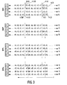
- the 6B words are each provided with a word synchronizing characteristic. Since the four parallel 5B/6B block encoding arrangements 1 to 4 are controlled by the same 28 MHz clock signal and the block encoding arrangements 1 to 4 are identical, the 6B words will appear with the same phases at the outputs 60 to 63 of the block encoding arrangements. This is shown schematically in the time-sequence diagram of Figure 2.
- the word synchronization characteristics K(l) ... K(4) shown symbolically by means of upright lines arrive at the same instant at the outputs 60 ... 63 of the block encoding arrangements. Consequently, the mutual phase difference between the synchronization characteristics is equal to 0 degrees.
- the composite digital signal is applied to the input 66 of the receiver section II of the digital transmission system via the digital path 10.
- the clock signal which is used for further signal processing in the receiver portion II of the transmission system is recovered from the composite digital signal.
- the recovered 672 MHz clock signal is applied to the clock input of the multiplexer 11 and via a divider 19 to the clock inputs of the block decoding arrangements 12 to 15.
- the synchronization characteristics K(l) and K(10) have a time lead relative to the other synchronization characteristics K(2) to K(4) and K(20) to K(40), respectively.
- the synchronization characteristics K(l) and K(2) lead the synchronization characteristics K(3) and K(4).
- the synchronization characteristics K(10) and K.(20) likewise have a time lead relative to the characteristics K(30) and K(40).
- the synchronization characteristic K(4) has a time lag relative to the other characteristics K(l) to K(3).
- the characteristic K(40) likewise lags the other characteristics K(10) to K(30).
- phase positions as shown in the Figures3b to 3d are detected by means of the phase comparator arrangement 16, whereafter a control signal is applied to the matrix switch 18 for establishing synchronization between the multiplexer 6 and the demultiplexer 11.
- the matrix switch 18 will be adjusted to the position shown in Figure 4a with the aid of the control signal produced by the phase comparator 16.
- the inputs 54, 55, 56 and 57 are connected to the respective outputs 44, 45, 46 and 47.
- the original digital signal streams A, B, C and D are then again available in the appropriate sequence at said outputs of the matrix switch.
- the matrix switch When the phase comparator 16 detects a phase position as shown in Figure 3b, the matrix switch will be adjusted to the position shown in Figure 4b with the aid of the control signal produced by the phase comparator 16.
- the inputs 54, 55, 56 and 57 of the matrix switch 18 are through-connected to the respective outputs 45, 46, 47 and 44.
- the original digital signal streams A, B, C and D are then again available in the appropriate sequence at said outputs of the matrix switch 18.
- the matrix switch 18 When the phase comparator detects a phase position as shown in Figure 3c, the matrix switch 18 will be adjusted to the position shown in Figure 4c with the aid of the control signal produced by the phase comparator 16.
- the inputs 54, 55, 56 and 57 of the matrix switch 18 are through-connected to the respective outputs 46, 47, 44 and 45.
- the original digital signal streams A, B, C and D are then again available in the appropriate sequence at said outputs of the matrix switch 18.
- the matrix switch 18 When the phase comparator 16 detects a phase position as shown in Figure 3d, the matrix switch 18 will be adjusted to the position shown in Figure 4d with the aid of the control signal produced by the phase comparator 16.
- the input 54, 55, 56 and 57 of the matrix switch 18 are through-connected to the respective outputs 47, 44, 45 and 46.
- the original digital signal streams A, B, C and D are then again available in the appropriate sequence at said outputs of the matrix switch 18.
- Synchronizing the transmitter portion and the receiver portion of a higher order digital transmission system in the above-described manner, using a matrix switch, has the advantage that this process occurs at a N times lower symbol rate.
- N 4.
- the fact that the block decoding arrangements 12 to 15 are likewise operated at a N times lower symbol rate is one of the reasons that it is possible to integrate said matrix switch and block decoding arrangements inspite of the high symbol rate of the digital signal incoming at the output 66 of the receive portion II.
- Using the matrix switch has the additional advantage that no information is lost because of the fact that during synchronization of the multiplexer 6 and the demultiplexer 11 the block decoding arrangements are mutually not out of synchronization. Information is indeed lost in those synchronization methods in which synchronization of the multiplexer and the demultiplexer is accomplished by means of suppressing one or more clock pulses of the demultiplexer write clock. Furthermore, in these methods, pulse suppression is effected at the highest symbol rate of the transmission system.
- the described multiplexing method renders it possible to have all the signal processing operations, such as scrambling, justifying, line-coding, error-monitoring and word synchronization at a N times lower symbol rate.
- the multiplexer 6 and the demultiplexer 11 can be realized with the aid of a symbol parallel/series converter and a symbol series/parallel converter. It is also not necessary to add frame words and prolonged frame synchronization techniques.
- Figure 5 shows an embodiment of a block decoding arrangement. It comprises an input shift register 30, a buffer 31, a decoder unit 32,an output shift register 33 and a word synchronizer 34.
- a word having 6 binary symbols is written into the series register 30 via the input 35; see, for example, Figure 3a the word a l ...a 6 .
- the word synchronizer 34 produces, after detection of the synchronization characteristic K(40) a pulse in response to which the content of the series register 30 is transferred to the buffer 31. Said word synchronization characteristic is also applied to an input of the phase comparator 16 via the line 40.
- the decoder unit 32 the word having 6 binary symbols is converted into a word having 5 binary symbols which is applied in parallel to the output register 33. This output register is read with the aid of the 140 MHz clock signal present at the clock input 37.
Landscapes
- Engineering & Computer Science (AREA)
- Computer Networks & Wireless Communication (AREA)
- Signal Processing (AREA)
- Microelectronics & Electronic Packaging (AREA)
- Time-Division Multiplex Systems (AREA)
- Synchronisation In Digital Transmission Systems (AREA)
Applications Claiming Priority (2)
| Application Number | Priority Date | Filing Date | Title |
|---|---|---|---|
| NL8501737 | 1985-06-17 | ||
| NL8501737A NL8501737A (nl) | 1985-06-17 | 1985-06-17 | Hogere orde digitaal transmissiesysteem voorzien van een multiplexer en een demultiplexer. |
Publications (2)
| Publication Number | Publication Date |
|---|---|
| EP0206408A1 true EP0206408A1 (de) | 1986-12-30 |
| EP0206408B1 EP0206408B1 (de) | 1991-12-27 |
Family
ID=19846151
Family Applications (1)
| Application Number | Title | Priority Date | Filing Date |
|---|---|---|---|
| EP86201032A Expired EP0206408B1 (de) | 1985-06-17 | 1986-06-16 | Digitales Übertragungssystem höherer Ordnung welches einen Multiplexer und einen Demultiplexer enthält |
Country Status (6)
| Country | Link |
|---|---|
| US (1) | US4759018A (de) |
| EP (1) | EP0206408B1 (de) |
| JP (1) | JPH0710058B2 (de) |
| CA (1) | CA1261081A (de) |
| DE (1) | DE3683088D1 (de) |
| NL (1) | NL8501737A (de) |
Cited By (2)
| Publication number | Priority date | Publication date | Assignee | Title |
|---|---|---|---|---|
| WO1988010036A1 (en) * | 1987-06-05 | 1988-12-15 | Bell Communications Research, Inc. | High speed scrambling at lower clock speeds |
| EP0548648A3 (en) * | 1991-12-12 | 1995-05-03 | Alcatel Nv | 1:n ring-type signal protection apparatus |
Families Citing this family (34)
| Publication number | Priority date | Publication date | Assignee | Title |
|---|---|---|---|---|
| JPS63236432A (ja) * | 1987-03-25 | 1988-10-03 | Fujitsu Ltd | Bsi化ビツトインタリ−ブ多重方式 |
| US4891808A (en) * | 1987-12-24 | 1990-01-02 | Coherent Communication Systems Corp. | Self-synchronizing multiplexer |
| US5018142A (en) * | 1988-03-04 | 1991-05-21 | Digital Equipment Corporation | Technique for organizing and coding serial binary data from a plurality of data lines for transmission over a single transmission line |
| JPH0773219B2 (ja) * | 1988-06-16 | 1995-08-02 | 富士通株式会社 | 並直列変換装置 |
| EP0358831A1 (de) * | 1988-09-13 | 1990-03-21 | International Business Machines Corporation | Multiplexierungssystemeinstellung durch Maskenregister |
| US4926423A (en) * | 1988-09-30 | 1990-05-15 | The Trustees Of Columbia University In The City Of New York | Time-division-multiplexed data transmission system |
| US4991975A (en) * | 1988-11-22 | 1991-02-12 | At&T Bell Laboratories | Division multiplexing and demultiplexing means lightwave communication system comprising optical time |
| US4987570A (en) * | 1989-02-09 | 1991-01-22 | Data General Corporation | Methods and apparatus for performing time interleaved multiplexed rate adaptation for sub-rate channels in a digital data communication system |
| GB8905533D0 (en) * | 1989-03-10 | 1989-04-19 | Plessey Telecomm | Pcm communication system |
| JP3053094B2 (ja) * | 1989-03-27 | 2000-06-19 | 株式会社日立製作所 | ディジタル信号の統計的多重化方法 |
| JPH03105769A (ja) * | 1989-09-20 | 1991-05-02 | Matsushita Electric Ind Co Ltd | 情報再生装置 |
| US5187575A (en) * | 1989-12-29 | 1993-02-16 | Massachusetts Institute Of Technology | Source adaptive television system |
| USH967H (en) | 1990-01-30 | 1991-09-03 | The United States Of America As Represented By The United States Department Of Energy | High speed, long distance, data transmission multiplexing circuit |
| US5444491A (en) * | 1993-02-26 | 1995-08-22 | Massachusetts Institute Of Technology | Television system with multiple transmission formats |
| US5726976A (en) * | 1993-04-06 | 1998-03-10 | Bay Networks Group, Inc. | Congestion sense controlled access for a star configured network |
| US5825755A (en) * | 1994-08-10 | 1998-10-20 | Bay Networks, Inc. | Method and apparatus for switching between full-duplex and half-duplex CSMA/CD systems |
| US5771073A (en) * | 1995-06-07 | 1998-06-23 | Massachusetts Institute Of Technology | Advanced television system using a different encoding technique for non-image areas |
| DE19536518C2 (de) * | 1995-09-29 | 1998-07-09 | Siemens Ag | Verfahren zur Aufrechterhaltung des mikrosynchronen Betriebs von gedoppelten informationsverarbeitenden Einheiten |
| US5835498A (en) * | 1995-10-05 | 1998-11-10 | Silicon Image, Inc. | System and method for sending multiple data signals over a serial link |
| US5940456A (en) * | 1996-06-20 | 1999-08-17 | Ut Starcom, Inc. | Synchronous plesiochronous digital hierarchy transmission systems |
| JP3125682B2 (ja) * | 1996-06-21 | 2001-01-22 | 日本電気株式会社 | クロック供給方式及びクロック供給システム |
| US6449071B1 (en) | 1998-06-22 | 2002-09-10 | Scientific-Atlanta, Inc. | Digital signal processing optical transmitter |
| US6373611B1 (en) | 1998-06-22 | 2002-04-16 | Scientific-Atlanta, Inc. | Digital optical transmitter |
| US6356374B1 (en) | 1998-10-09 | 2002-03-12 | Scientific-Atlanta, Inc. | Digital optical transmitter |
| US6356369B1 (en) | 1999-02-22 | 2002-03-12 | Scientific-Atlanta, Inc. | Digital optical transmitter for processing externally generated information in the reverse path |
| US6523177B1 (en) * | 1999-04-01 | 2003-02-18 | Scientific-Atlanta, Inc. | Cable television system with digital reverse path architecture |
| US6437895B1 (en) | 1999-04-05 | 2002-08-20 | Scientific-Atlanta, Inc. | Digital optical transmitter with compression |
| DE19943739A1 (de) * | 1999-09-03 | 2001-05-10 | Infineon Technologies Ag | Vorrichtung und Verfahren zum Laufzeitausgleich |
| US7046700B1 (en) * | 2001-03-08 | 2006-05-16 | Nortel Networks Limited | Spectrally invisible framing of high error rate data signals |
| DE60108728T2 (de) * | 2001-06-15 | 2006-05-11 | Lucent Technologies Inc. | Verfahren und ein Vorrichtung zum Übersenden und Empfangen gemultiplexter untergeordneter Signale |
| US20040208552A1 (en) * | 2002-05-08 | 2004-10-21 | Gordon Harney | Architectural switching arrangement for core optical networks |
| KR100762655B1 (ko) * | 2005-08-12 | 2007-10-01 | 삼성전자주식회사 | 통신 시스템에서 데이터 전송 장치 및 방법 |
| DE112012003389A5 (de) * | 2011-08-16 | 2014-04-30 | Silicon Line Gmbh | Schaltungsanordnung und Verfahren zum Kodieren und/oder Dekodieren |
| CN110364202B (zh) * | 2019-07-22 | 2021-08-24 | 上海兆芯集成电路有限公司 | 存储器装置 |
Citations (2)
| Publication number | Priority date | Publication date | Assignee | Title |
|---|---|---|---|---|
| EP0088432A1 (de) * | 1982-03-09 | 1983-09-14 | Nec Corporation | Multiplexereinrichtung mit nBmB-Kodierer |
| EP0101056A2 (de) * | 1982-08-12 | 1984-02-22 | Siemens Aktiengesellschaft | Synchronisieranordnung |
Family Cites Families (4)
| Publication number | Priority date | Publication date | Assignee | Title |
|---|---|---|---|---|
| US4121217A (en) * | 1976-08-06 | 1978-10-17 | Southern Pacific Communications Company (Spcc) | Data transmission network interface unit |
| US4143246A (en) * | 1977-09-06 | 1979-03-06 | Bell Telephone Laboratories, Incorporated | Time division line interface circuit |
| US4276646A (en) * | 1979-11-05 | 1981-06-30 | Texas Instruments Incorporated | Method and apparatus for detecting errors in a data set |
| JPS5731247A (en) * | 1980-08-01 | 1982-02-19 | Hitachi Ltd | Multiplexing tramsmission system |
-
1985
- 1985-06-17 NL NL8501737A patent/NL8501737A/nl not_active Application Discontinuation
-
1986
- 1986-06-12 CA CA000511479A patent/CA1261081A/en not_active Expired
- 1986-06-13 JP JP61136357A patent/JPH0710058B2/ja not_active Expired - Lifetime
- 1986-06-16 EP EP86201032A patent/EP0206408B1/de not_active Expired
- 1986-06-16 DE DE8686201032T patent/DE3683088D1/de not_active Expired - Lifetime
- 1986-06-17 US US06/875,196 patent/US4759018A/en not_active Expired - Lifetime
Patent Citations (2)
| Publication number | Priority date | Publication date | Assignee | Title |
|---|---|---|---|---|
| EP0088432A1 (de) * | 1982-03-09 | 1983-09-14 | Nec Corporation | Multiplexereinrichtung mit nBmB-Kodierer |
| EP0101056A2 (de) * | 1982-08-12 | 1984-02-22 | Siemens Aktiengesellschaft | Synchronisieranordnung |
Non-Patent Citations (5)
| Title |
|---|
| CCITT Livre Jaune, Tome 3 - Fascicule III.3. Réseaux numériques. Systèmes de transmission et équipement de multiplexage. Avis G701-G941, VIIe Assemblée Plénière, pages 218-225, 10th-21st November 1980, Genève, CH * |
| ELECTRICAL COMMUNICATION, vol. 57, no. 3, 1982, pages 251-258, Heidenheim, DE; A. BARBETTA et al.: "Digital multiplexers for rates from 2 to 565 Mbits-1 * |
| IEE PROCEEDINGS, vol. 132, no. 2, Pts E and I, March/April 1985, pages 68-72, Old Woking, Surrey, GB; I.C. WOOD et al.: "Design techniques for a 565/680 Mbit/s coder/decoder" * |
| IEEE JOURNAL OF SOLID-STATE CIRCUITS, vol. SC-14, no. 5, October 1979, pages 812-817, IEEE, New York, US; J.B. HUGHES et al.: "A versatile ECL multiplexer IC for the Gbit/s range" * |
| NACHRICHTENTECHNISCHE ZEITSCHRIFT NTZ, vol. 36, no. 1, January 1983, pages 16-21, Berlin, DE; H. HOFMEISTER: "Digitaler Multiplexer für vier plesiochrone 140-Mbit/s-Digitalsignale" * |
Cited By (2)
| Publication number | Priority date | Publication date | Assignee | Title |
|---|---|---|---|---|
| WO1988010036A1 (en) * | 1987-06-05 | 1988-12-15 | Bell Communications Research, Inc. | High speed scrambling at lower clock speeds |
| EP0548648A3 (en) * | 1991-12-12 | 1995-05-03 | Alcatel Nv | 1:n ring-type signal protection apparatus |
Also Published As
| Publication number | Publication date |
|---|---|
| EP0206408B1 (de) | 1991-12-27 |
| CA1261081A (en) | 1989-09-26 |
| JPH0710058B2 (ja) | 1995-02-01 |
| NL8501737A (nl) | 1987-01-16 |
| US4759018A (en) | 1988-07-19 |
| DE3683088D1 (de) | 1992-02-06 |
| JPS6256035A (ja) | 1987-03-11 |
Similar Documents
| Publication | Publication Date | Title |
|---|---|---|
| EP0206408B1 (de) | Digitales Übertragungssystem höherer Ordnung welches einen Multiplexer und einen Demultiplexer enthält | |
| US4689661A (en) | Method of simultaneously transmitting a plurality of television signals on a single radio link and apparatus adapted to carry out said method | |
| US4520480A (en) | Digital transmission system | |
| EP0533091B1 (de) | Verfahren zur parallelen Übertragung | |
| US3862373A (en) | Adaptive sampling rate time division multiplexer and method | |
| GB2182528A (en) | Stochastic time division multiplexing | |
| GB2191662A (en) | Parallel transmission system | |
| USRE29215E (en) | Cross-office connecting scheme for interconnecting multiplexers and central office terminals | |
| US4736464A (en) | Method for the additional transmission of information via a digital auxiliary channel, in an optical transmission system | |
| US4595907A (en) | PCM data translating apparatus | |
| US4829518A (en) | Multiplexing apparatus having BSI-code processing and bit interleave functions | |
| EP0206409B1 (de) | Digitales Übertragungssystem höherer Ordnung welches einen Multiplexer und einen Demultiplexer enthält | |
| US4271509A (en) | Supervisory signaling for digital channel banks | |
| US3908087A (en) | Time-division telecommunication system for the transmission of data via switched connections | |
| FI98581C (fi) | PCM-viestijärjestelmä | |
| US3065303A (en) | Input i | |
| CA1200934A (en) | Synchronising arrangement | |
| US4876695A (en) | Digital data transmission system having additional bits for auxiliary data | |
| US4099029A (en) | Asynchronous pcm common decoding apparatus | |
| US4498167A (en) | TDM Communication system | |
| US3359372A (en) | De burro | |
| WO1997008858A1 (en) | Time multiplexing/demultiplexing method | |
| US3627945A (en) | Transmission of asynchronous telegraphic signals | |
| CA1089962A (en) | Bit switching of word synchronized data | |
| JP2541121B2 (ja) | Ds3フレ―ム送受信装置 |
Legal Events
| Date | Code | Title | Description |
|---|---|---|---|
| PUAI | Public reference made under article 153(3) epc to a published international application that has entered the european phase |
Free format text: ORIGINAL CODE: 0009012 |
|
| AK | Designated contracting states |
Kind code of ref document: A1 Designated state(s): CH DE FR GB IT LI NL SE |
|
| 17P | Request for examination filed |
Effective date: 19870515 |
|
| 17Q | First examination report despatched |
Effective date: 19890109 |
|
| RAP1 | Party data changed (applicant data changed or rights of an application transferred) |
Owner name: AT&T NETWORK SYSTEMS INTERNATIONAL B.V. Owner name: APT NEDERLAND B.V. |
|
| GRAA | (expected) grant |
Free format text: ORIGINAL CODE: 0009210 |
|
| RAP3 | Party data changed (applicant data changed or rights of an application transferred) |
Owner name: AT&T NETWORK SYSTEMS INTERNATIONAL B.V. Owner name: AT&T NETWORK SYSTEMS NEDERLAND B.V. |
|
| AK | Designated contracting states |
Kind code of ref document: B1 Designated state(s): CH DE FR GB IT LI NL SE |
|
| REF | Corresponds to: |
Ref document number: 3683088 Country of ref document: DE Date of ref document: 19920206 |
|
| ET | Fr: translation filed | ||
| ITF | It: translation for a ep patent filed | ||
| PLBE | No opposition filed within time limit |
Free format text: ORIGINAL CODE: 0009261 |
|
| STAA | Information on the status of an ep patent application or granted ep patent |
Free format text: STATUS: NO OPPOSITION FILED WITHIN TIME LIMIT |
|
| 26N | No opposition filed | ||
| EAL | Se: european patent in force in sweden |
Ref document number: 86201032.9 |
|
| PGFP | Annual fee paid to national office [announced via postgrant information from national office to epo] |
Ref country code: CH Payment date: 19990323 Year of fee payment: 14 |
|
| PGFP | Annual fee paid to national office [announced via postgrant information from national office to epo] |
Ref country code: SE Payment date: 20000327 Year of fee payment: 15 |
|
| PG25 | Lapsed in a contracting state [announced via postgrant information from national office to epo] |
Ref country code: LI Free format text: LAPSE BECAUSE OF NON-PAYMENT OF DUE FEES Effective date: 20000630 Ref country code: CH Free format text: LAPSE BECAUSE OF NON-PAYMENT OF DUE FEES Effective date: 20000630 |
|
| REG | Reference to a national code |
Ref country code: CH Ref legal event code: PL |
|
| PG25 | Lapsed in a contracting state [announced via postgrant information from national office to epo] |
Ref country code: SE Free format text: LAPSE BECAUSE OF NON-PAYMENT OF DUE FEES Effective date: 20010617 |
|
| REG | Reference to a national code |
Ref country code: GB Ref legal event code: IF02 |
|
| EUG | Se: european patent has lapsed |
Ref document number: 86201032.9 |
|
| PGFP | Annual fee paid to national office [announced via postgrant information from national office to epo] |
Ref country code: FR Payment date: 20020524 Year of fee payment: 17 |
|
| PGFP | Annual fee paid to national office [announced via postgrant information from national office to epo] |
Ref country code: GB Payment date: 20020527 Year of fee payment: 17 |
|
| PGFP | Annual fee paid to national office [announced via postgrant information from national office to epo] |
Ref country code: NL Payment date: 20020531 Year of fee payment: 17 |
|
| PGFP | Annual fee paid to national office [announced via postgrant information from national office to epo] |
Ref country code: DE Payment date: 20020628 Year of fee payment: 17 |
|
| PG25 | Lapsed in a contracting state [announced via postgrant information from national office to epo] |
Ref country code: GB Free format text: LAPSE BECAUSE OF NON-PAYMENT OF DUE FEES Effective date: 20030616 |
|
| PG25 | Lapsed in a contracting state [announced via postgrant information from national office to epo] |
Ref country code: NL Free format text: LAPSE BECAUSE OF NON-PAYMENT OF DUE FEES Effective date: 20040101 Ref country code: DE Free format text: LAPSE BECAUSE OF NON-PAYMENT OF DUE FEES Effective date: 20040101 |
|
| GBPC | Gb: european patent ceased through non-payment of renewal fee |
Effective date: 20030616 |
|
| PG25 | Lapsed in a contracting state [announced via postgrant information from national office to epo] |
Ref country code: FR Free format text: LAPSE BECAUSE OF NON-PAYMENT OF DUE FEES Effective date: 20040227 |
|
| NLV4 | Nl: lapsed or anulled due to non-payment of the annual fee |
Effective date: 20040101 |
|
| REG | Reference to a national code |
Ref country code: FR Ref legal event code: ST |
|
| PG25 | Lapsed in a contracting state [announced via postgrant information from national office to epo] |
Ref country code: IT Free format text: LAPSE BECAUSE OF NON-PAYMENT OF DUE FEES;WARNING: LAPSES OF ITALIAN PATENTS WITH EFFECTIVE DATE BEFORE 2007 MAY HAVE OCCURRED AT ANY TIME BEFORE 2007. THE CORRECT EFFECTIVE DATE MAY BE DIFFERENT FROM THE ONE RECORDED. Effective date: 20050616 |