EP0206602A1 - Machine à copier électrostatique - Google Patents
Machine à copier électrostatique Download PDFInfo
- Publication number
- EP0206602A1 EP0206602A1 EP86304335A EP86304335A EP0206602A1 EP 0206602 A1 EP0206602 A1 EP 0206602A1 EP 86304335 A EP86304335 A EP 86304335A EP 86304335 A EP86304335 A EP 86304335A EP 0206602 A1 EP0206602 A1 EP 0206602A1
- Authority
- EP
- European Patent Office
- Prior art keywords
- light
- original
- copying machine
- light blocking
- density
- Prior art date
- Legal status (The legal status is an assumption and is not a legal conclusion. Google has not performed a legal analysis and makes no representation as to the accuracy of the status listed.)
- Granted
Links
- 230000000903 blocking effect Effects 0.000 claims abstract description 32
- 239000011521 glass Substances 0.000 claims abstract description 16
- 230000003287 optical effect Effects 0.000 claims abstract description 16
- 238000001514 detection method Methods 0.000 claims abstract description 9
- 230000035945 sensitivity Effects 0.000 claims description 2
- 230000007423 decrease Effects 0.000 description 4
- 238000010586 diagram Methods 0.000 description 4
- 238000010276 construction Methods 0.000 description 3
- 239000008199 coating composition Substances 0.000 description 1
Images


Classifications
-
- G—PHYSICS
- G03—PHOTOGRAPHY; CINEMATOGRAPHY; ANALOGOUS TECHNIQUES USING WAVES OTHER THAN OPTICAL WAVES; ELECTROGRAPHY; HOLOGRAPHY
- G03G—ELECTROGRAPHY; ELECTROPHOTOGRAPHY; MAGNETOGRAPHY
- G03G15/00—Apparatus for electrographic processes using a charge pattern
- G03G15/50—Machine control of apparatus for electrographic processes using a charge pattern, e.g. regulating differents parts of the machine, multimode copiers, microprocessor control
- G03G15/5025—Machine control of apparatus for electrographic processes using a charge pattern, e.g. regulating differents parts of the machine, multimode copiers, microprocessor control by measuring the original characteristics, e.g. contrast, density
-
- G—PHYSICS
- G03—PHOTOGRAPHY; CINEMATOGRAPHY; ANALOGOUS TECHNIQUES USING WAVES OTHER THAN OPTICAL WAVES; ELECTROGRAPHY; HOLOGRAPHY
- G03G—ELECTROGRAPHY; ELECTROPHOTOGRAPHY; MAGNETOGRAPHY
- G03G15/00—Apparatus for electrographic processes using a charge pattern
- G03G15/60—Apparatus which relate to the handling of originals
- G03G15/605—Holders for originals or exposure platens
Definitions
- the present invention relates to improvements in electrostatic copying machines having the function of automatically controlling the image density in accordance with the density of originals.
- Examined Japanese Patent Publication SHO 54-36502 discloses a contact glass plate provided with a light blocking white portion at a reference position thereon to form a nonimage area having a width of about 0.5 to about 20 mm at the front end of copy paper and thereby prevent the front end of the copy paper from fitting around a heat fixing roller when the copy paper is brought into pressing contact with the roller for fixing so that the copy paper can be separated off free of trouble by a separating pawl.
- Electrostatic copying machines which have the function of automatically controlling the image density by detecting the density of an original from the light reflected therefrom and varying the quantity of light to be emitted by the optical system or the bias voltage of the developing unit.
- the above-mentioned light blocking white portion is provided in such a machine, there arises the problem that the front end of copy paper becomes black for the following reason.
- the light blocking white portion is exposed to light, an increased quantity of light is reflected therefrom, causing the automatic density control system to greatly decrease the amount of exposure during a period A-B corresponding to the light blocking portion as shown in Fig. 5.
- the presence of the light blocking white portion produces a lower average exposure value, entailing the problem that the overall image to be formed on copy paper becomes dark.
- the object of the present invention which has been accomplished to overcome the foregoing problems is to provide an electrostatic copying machine which has an automatic density control function and which is adapted to properly preclude the likelihood that the image density at the front end of copy paper will increase to a level higher than is needed and to obviate a reduction in the overall density of copy images, using a simple arrangement.
- the present invention provides an electrostatic copying machine having an optical system for exposing to light an original placed on a contact glass plate, sensor means for detecting the density of the original and control means for controlling image density in accordance with a detection signal from the sensor means, the glass plate being provided with a light blocking white portion at a reference position thereon where the front end of the original is placed.
- a light blocking colored area reflecting a smaller quantity of light than the light blocking white portion is provided in the white portion at least at the part thereof corresponding to the position of detection by the sensor means.
- the quantity of light emitted by the optical system and reflected by the less reflective light blocking colored area is detected by the sensor means, and the image density is controlled based on the detected value. Consequently, despite the provision of the light blocking white portion, the presence of the colored area precludes the likelihood that an image to be formed at the front end portion of copy paper and an overall image in the case of the prescanning system become dark.
- Fig. 1 schematically shows the interior construction of an electrostatic copying machine.
- the drawing shows a contact glass plate 1 on the top of the machine frame.
- the optical system 2 comprises an exposure lamp 21, a reflector 22, first to third mirrors 23 to 25, a condenser lens 26 and a fourth mirror 27.
- the exposure lamp 21, etc. reciprocatingly travel along the lower surface of the glass plate 1.
- An original 10 placed on the glass plate 1 is exposed to light during the forward travel of the movable members.
- the drum 3 is drivingly rotatable in the direction of arrow X by unillustrated drive means.
- a main charger 32 having a charge wire 31
- a developing unit 34 having a developing roller 33
- a transfer charger 35 With the rotation of the photosensitive drum 3, the surface of the drum 3 is sensitized by the charge wire 31 of the main charger 32 to which a high voltage is applied.
- the image of the original is then projected on the drum 3 by the optical system 2 to form an electrostatic latent image, which is developed by the unit 34.
- the developed image is transferred by the transfer charger 35 to copy paper dispensed from a paper cassette 11 and fed by a transport assembly 12.
- the copy paper is then separated from the drum 3 by the charger 36, thereafter sent to a fixing unit 14 by a discharge belt 13 and delivered onto a copy tray 15.
- the optical system 2 is provided with sensor means 27 comprising a photodiode or the like for detecting the density of the original 10 from a portion of the light emitted by the exposure lamp 21 against the glass plate 1 and reflected from the original 10.
- sensor means 27 comprising a photodiode or the like for detecting the density of the original 10 from a portion of the light emitted by the exposure lamp 21 against the glass plate 1 and reflected from the original 10.
- light is emitted by the exposure lamp 21 in response to an instruction from a print key 46, and the reflected light is detected by the sensor means 27.
- the detection signal is fed to a light quantity detecting circuit 41 of control means 4 and converted to a voltage signal.
- the voltage signal is delivered from the circuit 41 to a comparison circuit 42, in which the signal is compared with a reference voltage from a reference voltage circuit 43.
- the voltage signal from the light quantity detecting circuit 41 will be lower than the reference voltage.
- an instruction signal for causing the exposure lamp 21 to produce an increased quantity of light is fed to a lamp voltage generating circuit 45 via a limiting circuit 44.
- the circuit 45 applies a voltage in accordance with the instruction signal to the exposure lamp 21 to scan the original with a controlled quantity of light.
- the limiting circuit 44 is provided to prevent application of a voltage higher than a limit to the exposure lamp 21 and thereby prevent burnout of the lamp, for example, when the original has a very high density.
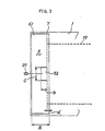
- a light blocking portion 5 is provided on the lower surface of the contact glass plate 1 at a reference position where the front end of the original 10 is placed, i.e., in the vicinity of the start position of the optical system 2.
- the light blocking portion 5 comprises a light blocking white area 51 formed, for example, by adhering a white tape with a width a to the glass plate 1 almost over the entire width thereof, and a light blocking gray area 52 formed on the surface of the white area 51 approximately at the widthwise midportion of the glass plate 1 where the original density sensor means 27 is disposed.
- the gray area 52 is provided by a tape or the like having a width b and a length c and is disposed outward of the reference position Y where the front end of the original is to be located.
- the light blocking gray area 52 has a lightness corresponding to the average density of originals (about N3 to 7 according to the lightness scale of JIS Z8721).
- the color of the gray area 52 is not always limited to gray insofar as the area 52 reflects a smaller quantity of light than the white area 51.
- any color is usable which has a wavelength outside the region of sensitivity wavelengths of the sensor of the original density sensor means 27. The following description is given with reference to the area 52 which is gray.
- the quantity of light reflected from the original 10 is detected by the sensor means 27, and the quantity of light of the exposure lamp 21 is controlled by the control means 4 according to the detected value along with development and transfer operation.
- the light reflected from the light blocking white area 51 impinges on the sensor means 27, with the result that the comparison circuit 42 recognizes an excessive quantity of light. Accordingly, during a period A-D corresponding to the white area 51 shown in Fig. 4, the quantity of light emanating from the exposure lamp 21 is so controlled that the quantity gradually decreases and then levels off.
- the control means 4 gives an instruction to increase the voltage to be applied to the exposure lamp 21. Consequently, during a period D-B' corresponding to the gray area 52, the quantity of light from the exposure lamp 21 gradually increases.
- the exposure of the original 10 is started at time B when an approximately standard quantity of light is reached, almost free of the influence of a period B'-B corresponding to the portion of the white area 51 having a very small width d as will be described below.
- the presence of the gray area 52 in the midportion of the light blocking white area 51 obviates the objectionable result that the amount of exposure for the front end portion of the original decreases under the influence of the white area 51 to darken the image at the front end of copy paper and the overall image in the case of the prescanning system. Further the white area 51 overlapping the foremost end of the original 10 over the length d forms a nonimage area on the copy paper for preventing the paper from fitting around the fixing roller.
- the length d which can be as small as about 5 mm for forming the nonimage area and need not be very large, will not result in a marked reduction in the amount of exposure.
- the present invention eliminates the need to use a complex arrangement such as one including a timer for interrupting the density control operation during the exposure of the white area and further has the advantage of assuring proper control at all times for machines equipped with a variable magnification device.
- the image density is controlled by varying the quantity of light of the exposure lamp 21, whereas the present invention is similarly applicable to apparatus wherein the image density is controllable by varying the bias voltage of the developing unit 34-
- the light blocking white area 51, as well as the gray area 52 may be provided by applying a coating composition to the lower or upper surface of the glass plate 1.
- the position, size, etc. of the light blocking gray area 52 can be altered variously as required, provided that the gray area 52 is located at the position of detection by the density sensor means 27.
- the present invention is applicable not only to copying machines of the type described wherein the optical system is movable but also to those having a movable document carriage.
Landscapes
- Physics & Mathematics (AREA)
- General Physics & Mathematics (AREA)
- Engineering & Computer Science (AREA)
- Microelectronics & Electronic Packaging (AREA)
- Exposure Or Original Feeding In Electrophotography (AREA)
- Control Or Security For Electrophotography (AREA)
- Control Of Exposure In Printing And Copying (AREA)
Applications Claiming Priority (2)
| Application Number | Priority Date | Filing Date | Title |
|---|---|---|---|
| JP91370/85U | 1985-06-17 | ||
| JP9137085 | 1985-06-17 |
Publications (2)
| Publication Number | Publication Date |
|---|---|
| EP0206602A1 true EP0206602A1 (fr) | 1986-12-30 |
| EP0206602B1 EP0206602B1 (fr) | 1989-12-27 |
Family
ID=14024487
Family Applications (1)
| Application Number | Title | Priority Date | Filing Date |
|---|---|---|---|
| EP86304335A Expired EP0206602B1 (fr) | 1985-06-17 | 1986-06-06 | Machine à copier électrostatique |
Country Status (3)
| Country | Link |
|---|---|
| US (1) | US4725868A (fr) |
| EP (1) | EP0206602B1 (fr) |
| DE (1) | DE3667867D1 (fr) |
Families Citing this family (3)
| Publication number | Priority date | Publication date | Assignee | Title |
|---|---|---|---|---|
| US4879576A (en) * | 1987-03-13 | 1989-11-07 | Minolta Camera Kabushiki Kaisha | Exposure control device and method |
| US4982232A (en) * | 1987-04-20 | 1991-01-01 | Minolta Camera Kabushiki Kaisha | Exposure control system of image forming apparatus |
| US20070002395A1 (en) * | 2005-06-29 | 2007-01-04 | Samsung Electronics, Co., Ltd | Scanning apparatus |
Citations (4)
| Publication number | Priority date | Publication date | Assignee | Title |
|---|---|---|---|---|
| FR2046473A5 (fr) * | 1969-04-25 | 1971-03-05 | Agfa Gevaert Ag | |
| US3834807A (en) * | 1974-02-14 | 1974-09-10 | Ibm | Copier with leading edge image control |
| GB2061825A (en) * | 1979-10-22 | 1981-05-20 | Nashua Corp | Automatic bias control system for electrophotographic copier |
| EP0077988A2 (fr) * | 1981-10-23 | 1983-05-04 | Kabushiki Kaisha Toshiba | Détecteur de densité d'image pour un dispositif de formation d'image |
Family Cites Families (4)
| Publication number | Priority date | Publication date | Assignee | Title |
|---|---|---|---|---|
| US4226525A (en) * | 1976-10-19 | 1980-10-07 | Ricoh Company, Ltd. | Electrostatic copying machine |
| DE2857218C3 (de) * | 1977-02-23 | 1989-08-10 | Ricoh Co., Ltd., Tokio/Tokyo | Verfahren zum Konstanthalten optimaler Bedingungen bei der elektrografischen Vervielfältigung |
| JPS5436725A (en) * | 1977-08-26 | 1979-03-17 | Ricoh Co Ltd | Zerographic copying method |
| JPS55159458A (en) * | 1979-05-31 | 1980-12-11 | Konishiroku Photo Ind Co Ltd | Black belt removing method in composite information recorder |
-
1986
- 1986-06-02 US US06/869,747 patent/US4725868A/en not_active Expired - Lifetime
- 1986-06-06 DE DE8686304335T patent/DE3667867D1/de not_active Expired - Lifetime
- 1986-06-06 EP EP86304335A patent/EP0206602B1/fr not_active Expired
Patent Citations (4)
| Publication number | Priority date | Publication date | Assignee | Title |
|---|---|---|---|---|
| FR2046473A5 (fr) * | 1969-04-25 | 1971-03-05 | Agfa Gevaert Ag | |
| US3834807A (en) * | 1974-02-14 | 1974-09-10 | Ibm | Copier with leading edge image control |
| GB2061825A (en) * | 1979-10-22 | 1981-05-20 | Nashua Corp | Automatic bias control system for electrophotographic copier |
| EP0077988A2 (fr) * | 1981-10-23 | 1983-05-04 | Kabushiki Kaisha Toshiba | Détecteur de densité d'image pour un dispositif de formation d'image |
Also Published As
| Publication number | Publication date |
|---|---|
| US4725868A (en) | 1988-02-16 |
| DE3667867D1 (de) | 1990-02-01 |
| EP0206602B1 (fr) | 1989-12-27 |
Similar Documents
| Publication | Publication Date | Title |
|---|---|---|
| US4657377A (en) | Image formation apparatus with variable density control | |
| EP0493088B1 (fr) | Un dispositif de commande de densité d'image utilisable dans un appareil de formation d'images | |
| EP0206602B1 (fr) | Machine à copier électrostatique | |
| US4922296A (en) | Image reproducing apparatus controlled in response to detected density of an original image | |
| US4588283A (en) | Electrophotographic copying apparatus with original light detector | |
| JPH0526584Y2 (fr) | ||
| JPS63137224A (ja) | 自動露光装置 | |
| US5072260A (en) | Image forming apparatus having analog and digital exposure means | |
| JPH01277256A (ja) | 画像形成装置 | |
| JPS59210433A (ja) | 複写装置 | |
| JPH0642096B2 (ja) | 乾式電子写真複写機における自動画像濃度制御装置 | |
| JP2919876B2 (ja) | 画像形成装置の等倍度表示装置 | |
| JPH0524923Y2 (fr) | ||
| JPH0519143B2 (fr) | ||
| JPH0455316Y2 (fr) | ||
| JPH0695508A (ja) | 複写機 | |
| JPS639206B2 (fr) | ||
| JPS60256129A (ja) | 複写機における光量検出装置 | |
| JPS58162978A (ja) | 画像形成装置 | |
| JPH04218073A (ja) | 画像形成装置 | |
| JPH09106222A (ja) | 画像形成装置および画像形成方法 | |
| JPS58184161A (ja) | 画像処理装置 | |
| JPH0785181B2 (ja) | 複写機 | |
| JPS6117159A (ja) | 電子写真装置 | |
| JPH0895433A (ja) | 画像形成装置 |
Legal Events
| Date | Code | Title | Description |
|---|---|---|---|
| PUAI | Public reference made under article 153(3) epc to a published international application that has entered the european phase |
Free format text: ORIGINAL CODE: 0009012 |
|
| AK | Designated contracting states |
Kind code of ref document: A1 Designated state(s): DE FR GB NL |
|
| 17P | Request for examination filed |
Effective date: 19870622 |
|
| 17Q | First examination report despatched |
Effective date: 19890419 |
|
| GRAA | (expected) grant |
Free format text: ORIGINAL CODE: 0009210 |
|
| AK | Designated contracting states |
Kind code of ref document: B1 Designated state(s): DE FR GB NL |
|
| REF | Corresponds to: |
Ref document number: 3667867 Country of ref document: DE Date of ref document: 19900201 |
|
| ET | Fr: translation filed | ||
| PLBE | No opposition filed within time limit |
Free format text: ORIGINAL CODE: 0009261 |
|
| STAA | Information on the status of an ep patent application or granted ep patent |
Free format text: STATUS: NO OPPOSITION FILED WITHIN TIME LIMIT |
|
| 26N | No opposition filed | ||
| PGFP | Annual fee paid to national office [announced via postgrant information from national office to epo] |
Ref country code: GB Payment date: 19960528 Year of fee payment: 11 |
|
| PGFP | Annual fee paid to national office [announced via postgrant information from national office to epo] |
Ref country code: FR Payment date: 19960611 Year of fee payment: 11 |
|
| PGFP | Annual fee paid to national office [announced via postgrant information from national office to epo] |
Ref country code: DE Payment date: 19960612 Year of fee payment: 11 |
|
| PGFP | Annual fee paid to national office [announced via postgrant information from national office to epo] |
Ref country code: NL Payment date: 19960626 Year of fee payment: 11 |
|
| PG25 | Lapsed in a contracting state [announced via postgrant information from national office to epo] |
Ref country code: GB Free format text: LAPSE BECAUSE OF NON-PAYMENT OF DUE FEES Effective date: 19970606 |
|
| PG25 | Lapsed in a contracting state [announced via postgrant information from national office to epo] |
Ref country code: NL Effective date: 19980101 |
|
| GBPC | Gb: european patent ceased through non-payment of renewal fee |
Effective date: 19970606 |
|
| PG25 | Lapsed in a contracting state [announced via postgrant information from national office to epo] |
Ref country code: FR Free format text: LAPSE BECAUSE OF NON-PAYMENT OF DUE FEES Effective date: 19980227 |
|
| NLV4 | Nl: lapsed or anulled due to non-payment of the annual fee |
Effective date: 19980101 |
|
| PG25 | Lapsed in a contracting state [announced via postgrant information from national office to epo] |
Ref country code: DE Free format text: LAPSE BECAUSE OF NON-PAYMENT OF DUE FEES Effective date: 19980303 |
|
| REG | Reference to a national code |
Ref country code: FR Ref legal event code: ST |
|
| REG | Reference to a national code |
Ref country code: FR Ref legal event code: ST |