EP0206708A2 - Dispositif pour l'alimentation automatique en eau - Google Patents
Dispositif pour l'alimentation automatique en eau Download PDFInfo
- Publication number
- EP0206708A2 EP0206708A2 EP86304608A EP86304608A EP0206708A2 EP 0206708 A2 EP0206708 A2 EP 0206708A2 EP 86304608 A EP86304608 A EP 86304608A EP 86304608 A EP86304608 A EP 86304608A EP 0206708 A2 EP0206708 A2 EP 0206708A2
- Authority
- EP
- European Patent Office
- Prior art keywords
- water
- water feeding
- storage tank
- head
- earth
- Prior art date
- Legal status (The legal status is an assumption and is not a legal conclusion. Google has not performed a legal analysis and makes no representation as to the accuracy of the status listed.)
- Withdrawn
Links
Images


Classifications
-
- A—HUMAN NECESSITIES
- A01—AGRICULTURE; FORESTRY; ANIMAL HUSBANDRY; HUNTING; TRAPPING; FISHING
- A01G—HORTICULTURE; CULTIVATION OF VEGETABLES, FLOWERS, RICE, FRUIT, VINES, HOPS OR SEAWEED; FORESTRY; WATERING
- A01G27/00—Self-acting watering devices, e.g. for flower-pots
- A01G27/008—Component parts, e.g. dispensing fittings, level indicators
-
- A—HUMAN NECESSITIES
- A01—AGRICULTURE; FORESTRY; ANIMAL HUSBANDRY; HUNTING; TRAPPING; FISHING
- A01G—HORTICULTURE; CULTIVATION OF VEGETABLES, FLOWERS, RICE, FRUIT, VINES, HOPS OR SEAWEED; FORESTRY; WATERING
- A01G27/00—Self-acting watering devices, e.g. for flower-pots
Definitions
- the method is practised with one or more water supply pipes extending above a line of growing plants in a cultivating field allowing a predetermined volume of water to drip onto the ground in the region in which the roots of the plants spread.
- This method has the advantage that no water will be fed to regions where watering is not required, the supply of water being concentrated into the required areas. This method therefore achieves a better use of the water supply from a source and, for a given quantity of water will achieve an increased rate of harvest of a crop.
- this water dripping method still involves a number of drawbacks. Specifically, it is difficult to properly adjust the rate of water drip from the supply pipes. There is again an unavoidable loss of water due to evaporation as the water is fed to the surface of the earth from above. In order to reach the roots, a volume of water greater than that which would be required simply for feeding the plants must be dripped onto the ground. In an effort further to improve on the foregoing proposal, it has been suggested to feed water by an underground system.
- a number of water supply tubes are connected one to another with water permeable tubes having a plurality of capillary pores formed thereon being interposed between adjacent water supply tubes, the end one of each run of water supply tubes being coupled to a water supply source and the water permeable pipes being embedded in the earth of the cultivating field.
- an automatic water feeding device of the type including a water storage tank, a water feeding head and a water supply tube extending therebetween, characterised in that said water feeding head comprises: a generally tubular water feeding portion made of water permeable material and having a closed end, said water feeding portion being adapted to be plunged into the earth or other growing medium in the region of the roots of a plant to be watered, and a head portion made of water-tight material coupled to the upper open end of the water feeding portion; and in that an outlet port through which water to be fed is delivered to the head portion via said water supply tube is provided at a position in the vicinity of the bottom of the water storage tank, whereby the surface level of water in the water storage tank may be below the surface level of the earth or other growing medium into which the water feeding portion is plunged.
- the automatic water feeding device Xa includes a water storage tank 1 serving as water supply source, a water supply.tube 50 made of elastomeric material such as rubber or the like having excellent flexibility and a water feeding head 60 through which water is fed to the earth or other growing medium in the region of the roots of a plant to be watered.
- the water storage tank 1 is so designed that any person can easily carry it by themself, and is suitably made of a plastics material.
- the water storage tank 1 comprises a bottom 10, an intermediate portion 20 including a circumextending wall, and a top 30 assembled into an integral construction with the use of adhesive, and has a generally rectangular cross-section.
- the intermediate portion 20 has a front side plate 21 which is formed with a recess 22 in the area extending down from the upper end of the front side plate 21 to a position adjacent the bottom 10.
- a generally horizontally extending portion 23 in the recess 22 is provided with one or more spigot tubes 24 therethrough.
- one said tube is coupled at 26 to the lower end of a water level meter 27.
- the lower end of water supply tube 50 is fitted on to the upper end of another spigot tube.
- Fig. 1 shows a cap fitted on to the upper end of one said spigot tube 24 not in operation, thereby to inhibit a leakage of water therefrom.
- a funnel-shaped water inlet port 31 and a short air vent tube 35 are integrally formed in the top 30.
- the water inlet port 31 has a water supply pipe 32 connected thereto and extending down to a position adjacent the bottom 10.
- Air vent tube 25 is fitted with a screw 37 which is threadably engaged to a threaded air vent hole 36 to function as a vave, a packing 38 being interposed between the screw 37 and the lower end of threaded hole 36 which has a reduced diameter.
- the tank also has an upper front edge member 40 provided with a short tube (not shown) on to which the upper open end of the water level meter 27 is fitted and a plurality of cut-outs 41 for holding the water supply tubes 50 at an intermediate section thereof.
- the water supply tube 50 is an ordinary tube made of elastomeric material having excellent flexibility and it may be transparent or may be opaque. However, for convenience we prefer the tube to be transparent.
- the water feeding head 60 comprises a generally tubular water feeding portion 61 made of porous ceramic material adapted to be plunged into a flowerpot in the region where the roots of a plant spread in the earth or other growing medium and a head portion 62 made of watertight plastics material which is tightly engaged to the upper open end of the water feeding portion 61.
- the bottom end of the water feeding portion 61 is closed with a generally conical end.
- the above-mentioned water feeding portion preferably comprises unglazed pottery produced by the steps of mixing clay as the main raw material with fine synthetic resin powder and burning out the thus prepared mixture at an elevated temperature in the range of 1,200 to 1,600°C which evaporates the components of the synthetic resin powder. After completion of such evaporation a large number of very fine invisible capillary pores are left behind over the whole surface area of the unglazed pottery. Water will ooze through the capillary pores under the effect of differential pressure across the wall of the unglazed pottery.
- the water feeding portion has inner and outer diameters, thickness and length which may be selected in dependence upon the size of flowerpot and the kind of plant to be watered.
- the water feeding portion 61 has a hollow interior and its upper proximal end is open to the outside while its lower end is closed with a tapered generally conical portion.
- the water feeding portion 61 is designed in an elongated generally tubular configuration which allows it easily to be plunged into earth or other growing media.
- valve screw 37 is first rotated to displace it from the packing 38 to vent air through the air vent hole 36.
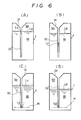
- the water feeding head 60 is located at a position above the water storage tank 1 and water W is then introduced into the water storage tank 1 via the water inlet port 31 (Fig. 6(A)).
- the valve screw 67 on the water feeding head 60 is loosened to displace it from the packing 66 to open the air vent hole 65.
- the water feeding head 60 is lowered below the level of water in the water storage tank 1 whereby both the water supply tube 50 and the water feeding head 60 are filled with water W.
- both the valve screws 37 and 67 are rotated to close the respective air vent holes 36 and 65.
- the water storage tank 1 of the device X a is placed at a position below the flowerpot 70 as shown in Fig. 5 and the water feeding portion 61 of the water feeding head 60 is then plunged into the earth or other growing medium T in the flowerpot 7Q until the skirt 68 of the head portion 62 is embedded in the earth.T. Water held in the water storage tank 1 will then ooze into the earth or other growing medium through the water feeding portion 61 absorbtion depending on the degree of dryness of the earth or other growing medium whereby water feeding is automatically effected.
- the volume of water W in the water storage tank 1 decreases correspondingly.
- the initial space S a in the water storage tank 1 is increased to a space S b corresponding to the reduction of water W in the water storage tank 1 whereby pressure in the space S b becomes less than atmospheric, because the interior of the water storage tank 1 is closed.
- the water level in the water supply pipe 32 is caused to lower corresponding to differential pressure between the atmospheric pressure and pressure in the space S b until a water level L f is reached.
- the pressure appearing in the horizontally extending plane H including the lower end of the water supply pipe 32 is maintained at a substantially constant level (i.e atmospheric) at all times irrespective of how much the space S d (Fig. 6(D)) in the water storage tank 1 exceeds the space S c at which the water level L in the water supply pipe 32 first reaches the lower end of the latter as shown in Fig. 6(C).
- Fig. 7 illustrates by way of a perspective view another embodiment of automatic water feeding device X b .
- the device X b is formed integrally with its flowerpot, plant holder or the like, which has a relatively thick wall thickness so as to accommodate the water tank of device X b . Since the device X b is otherwise substantially similar to the device X a in structure and function, the components of the device X b are identified by reference numerals corresponding to those of the device X but increased by 100, and it is therefore thought that a repeated description will not be required.
- the barrel portion of the flowerpot 170 is identified 171 and will be seen to have a substantial wall thickness.
- Fig. 8 schematically illustrates another embodiment of automatic water feeding device intended for use in large-scale cultivation, for example in a farm or horticultural nursery.
- the device X usable for such a large-scale cultivation is substantially similar to the device X a with the exception of increased capacity, its components are identified by reference numerals corresponding to those of the device X , but increased by 200, and a repeated description should not be necessary.
- the main water supply tube 250 divides into branched tubes 251a and 251b and those in turn have a plurality of twig tubes 252a and 252b leading thereoff and each in communication with a respective water feeding head 260.
- reference numerals 272a and 272b designate a ridge in.the farm field respectively.
- the embodiments of automatic water feeding device described hereinabove include a number of very significant features. Firstly, it will be seen that a sufficient volume of water is automatically fed to the region of the roots of a plant without any necessity for a consideration of the rate of evaporation of water fed from above by conventional watering means and without any need for a mechanical pumping means. Since operation of the embodiments of automatic watering device depend on the absorbtive power of the earth or other growing medium, which in turn depends on the degree of dryness of the earth at any one time, the earth should not become saturated and the wetted region of the earth will gradually increase by diffusion of water through the earth as the supplied water continues to ooze thereinto.
- Embodiments of device in accordance with the present invention can readily be used either for large-scale cultivation or for micro-cultivation on a flowerpot scale.
Landscapes
- Engineering & Computer Science (AREA)
- Water Supply & Treatment (AREA)
- Life Sciences & Earth Sciences (AREA)
- Environmental Sciences (AREA)
- Cultivation Receptacles Or Flower-Pots, Or Pots For Seedlings (AREA)
Applications Claiming Priority (4)
| Application Number | Priority Date | Filing Date | Title |
|---|---|---|---|
| JP9063685U JPS61207153U (fr) | 1985-06-14 | 1985-06-14 | |
| JP90635/85 | 1985-06-14 | ||
| JP9063585U JPS6221850U (fr) | 1985-06-14 | 1985-06-14 | |
| JP90636/85 | 1985-06-14 |
Publications (2)
| Publication Number | Publication Date |
|---|---|
| EP0206708A2 true EP0206708A2 (fr) | 1986-12-30 |
| EP0206708A3 EP0206708A3 (fr) | 1987-06-16 |
Family
ID=26432094
Family Applications (1)
| Application Number | Title | Priority Date | Filing Date |
|---|---|---|---|
| EP86304608A Withdrawn EP0206708A3 (fr) | 1985-06-14 | 1986-06-16 | Dispositif pour l'alimentation automatique en eau |
Country Status (2)
| Country | Link |
|---|---|
| EP (1) | EP0206708A3 (fr) |
| KR (1) | KR870000006A (fr) |
Cited By (6)
| Publication number | Priority date | Publication date | Assignee | Title |
|---|---|---|---|---|
| GB2240453A (en) * | 1990-02-02 | 1991-08-07 | William George Lyne | Self watering device for plants |
| EP0832556A3 (fr) * | 1996-09-27 | 1999-08-11 | Adedamola Adebayo Andu | Appareil d'irrigation automatique pour des plantes |
| AT501883B1 (de) * | 2005-09-12 | 2006-12-15 | Weninger Ges M B H | Selbsttätige einrichtung zur bewässerung von kulturpflanzen |
| US20160227718A1 (en) * | 2015-02-11 | 2016-08-11 | William Dunbar | Fluid Emitter concepts for feeding the root system of a plant |
| CN110291968A (zh) * | 2018-03-22 | 2019-10-01 | 榆林市榆阳区林业工作站 | 一种用于沙地造林插孔浇水装置 |
| CN111084080A (zh) * | 2020-01-19 | 2020-05-01 | 广州市植意科技有限公司 | 一种灌溉装置及灌溉系统 |
Family Cites Families (6)
| Publication number | Priority date | Publication date | Assignee | Title |
|---|---|---|---|---|
| AT256545B (de) * | 1965-06-29 | 1967-08-25 | Ipaco Internat Patent And Cons | Einrichtung zur dauernden Bewässerung von Kulturpflanzen |
| FR1566566A (fr) * | 1968-03-20 | 1969-05-09 | ||
| DE2416802C3 (de) * | 1974-04-06 | 1979-01-11 | Manfred Dr. 6314 Ulrichstein Kitz | Bewässerungsanlage für Gefäßpflanzen |
| DE2528748A1 (de) * | 1975-06-27 | 1976-12-30 | Manfred Dr Kitz | Bewaesserungsanlage fuer gefaesspflanzen |
| DE2655656A1 (de) * | 1975-12-12 | 1977-06-16 | Peter Weninger | Einrichtung zur versorgung von kulturpflanzen |
| DE3070640D1 (en) * | 1980-05-27 | 1985-06-20 | Ipaco Int Patent & Const Co | Device for permanently supplying water to plants |
-
1986
- 1986-06-14 KR KR1019860004725A patent/KR870000006A/ko not_active Withdrawn
- 1986-06-16 EP EP86304608A patent/EP0206708A3/fr not_active Withdrawn
Cited By (6)
| Publication number | Priority date | Publication date | Assignee | Title |
|---|---|---|---|---|
| GB2240453A (en) * | 1990-02-02 | 1991-08-07 | William George Lyne | Self watering device for plants |
| EP0832556A3 (fr) * | 1996-09-27 | 1999-08-11 | Adedamola Adebayo Andu | Appareil d'irrigation automatique pour des plantes |
| AT501883B1 (de) * | 2005-09-12 | 2006-12-15 | Weninger Ges M B H | Selbsttätige einrichtung zur bewässerung von kulturpflanzen |
| US20160227718A1 (en) * | 2015-02-11 | 2016-08-11 | William Dunbar | Fluid Emitter concepts for feeding the root system of a plant |
| CN110291968A (zh) * | 2018-03-22 | 2019-10-01 | 榆林市榆阳区林业工作站 | 一种用于沙地造林插孔浇水装置 |
| CN111084080A (zh) * | 2020-01-19 | 2020-05-01 | 广州市植意科技有限公司 | 一种灌溉装置及灌溉系统 |
Also Published As
| Publication number | Publication date |
|---|---|
| KR870000006A (ko) | 1987-02-16 |
| EP0206708A3 (fr) | 1987-06-16 |
Similar Documents
| Publication | Publication Date | Title |
|---|---|---|
| US4651468A (en) | Method and apparatus for natural fertilization and irrigation of plants | |
| US7798746B2 (en) | Modular, self contained, engineered irrigation landscape and flower bed panel | |
| EP1699285B1 (fr) | Systeme de gestion d'eau et de racines pour plantes en pots | |
| CA2607906C (fr) | Systeme d'irrigation et procedes associes | |
| US20100219265A1 (en) | Water irrigation system including drip irrigation emitters | |
| US5836106A (en) | Plant watering control device | |
| EP0136476A2 (fr) | Procédé et appareil pour la fertilisation et l'irrigation naturelle de plantes | |
| EP0206708A2 (fr) | Dispositif pour l'alimentation automatique en eau | |
| US4928427A (en) | Irrigation system | |
| JP5274850B2 (ja) | 地下灌漑システム | |
| CN215648400U (zh) | 一种植物栽培系统和植物栽培装置 | |
| CN203860115U (zh) | 植物容器 | |
| CN105075700A (zh) | 植物容器 | |
| RU2219760C1 (ru) | Система капельного орошения | |
| JP3198640U (ja) | 省力的底潅水多品種容器栽培システム | |
| AU2011224135B2 (en) | Irrigation system and associated methods | |
| JPH08107720A (ja) | 植物育成装置及び植物育成方法 | |
| CN113924956A (zh) | 一种节水型自动渗灌装置 | |
| CN217657235U (zh) | 一种园艺种植用地泉保湿节水花箱 | |
| JP2860320B2 (ja) | 自動潅水装置 | |
| JPH10113081A (ja) | 植物栽培装置及び植木棚 | |
| JPH1033074A (ja) | 自動潅水式プランター | |
| JP3100071U (ja) | 自動給水装置 | |
| AU2004298289B2 (en) | Root and water management system for potted plants | |
| JPH0313169Y2 (fr) |
Legal Events
| Date | Code | Title | Description |
|---|---|---|---|
| PUAI | Public reference made under article 153(3) epc to a published international application that has entered the european phase |
Free format text: ORIGINAL CODE: 0009012 |
|
| AK | Designated contracting states |
Kind code of ref document: A2 Designated state(s): DE FR GB IT NL |
|
| PUAL | Search report despatched |
Free format text: ORIGINAL CODE: 0009013 |
|
| AK | Designated contracting states |
Kind code of ref document: A3 Designated state(s): DE FR GB IT NL |
|
| STAA | Information on the status of an ep patent application or granted ep patent |
Free format text: STATUS: THE APPLICATION IS DEEMED TO BE WITHDRAWN |
|
| 18D | Application deemed to be withdrawn |
Effective date: 19871217 |
|
| RIN1 | Information on inventor provided before grant (corrected) |
Inventor name: TANIGAWA, HAJIME |