EP0206773A2 - Lame d'essuyage - Google Patents
Lame d'essuyage Download PDFInfo
- Publication number
- EP0206773A2 EP0206773A2 EP86304735A EP86304735A EP0206773A2 EP 0206773 A2 EP0206773 A2 EP 0206773A2 EP 86304735 A EP86304735 A EP 86304735A EP 86304735 A EP86304735 A EP 86304735A EP 0206773 A2 EP0206773 A2 EP 0206773A2
- Authority
- EP
- European Patent Office
- Prior art keywords
- blade
- wiper
- wiper blade
- blades
- opposing blades
- Prior art date
- Legal status (The legal status is an assumption and is not a legal conclusion. Google has not performed a legal analysis and makes no representation as to the accuracy of the status listed.)
- Withdrawn
Links
Images

Classifications
-
- B—PERFORMING OPERATIONS; TRANSPORTING
- B60—VEHICLES IN GENERAL
- B60S—SERVICING, CLEANING, REPAIRING, SUPPORTING, LIFTING, OR MANOEUVRING OF VEHICLES, NOT OTHERWISE PROVIDED FOR
- B60S1/00—Cleaning of vehicles
- B60S1/02—Cleaning windscreens, windows or optical devices
- B60S1/46—Cleaning windscreens, windows or optical devices using liquid; Windscreen washers
- B60S1/48—Liquid supply therefor
- B60S1/52—Arrangement of nozzles; Liquid spreading means
- B60S1/522—Arrangement of nozzles; Liquid spreading means moving liquid spreading means, e.g. arranged in wiper arms
- B60S1/524—Arrangement of nozzles; Liquid spreading means moving liquid spreading means, e.g. arranged in wiper arms arranged in wiper blades
-
- B—PERFORMING OPERATIONS; TRANSPORTING
- B60—VEHICLES IN GENERAL
- B60S—SERVICING, CLEANING, REPAIRING, SUPPORTING, LIFTING, OR MANOEUVRING OF VEHICLES, NOT OTHERWISE PROVIDED FOR
- B60S1/00—Cleaning of vehicles
- B60S1/02—Cleaning windscreens, windows or optical devices
- B60S1/04—Wipers or the like, e.g. scrapers
- B60S1/32—Wipers or the like, e.g. scrapers characterised by constructional features of wiper blade arms or blades
- B60S1/38—Wiper blades
- B60S2001/3827—Wiper blades characterised by the squeegee or blade rubber or wiping element
- B60S2001/3829—Wiper blades characterised by the squeegee or blade rubber or wiping element characterised by the material of the squeegee or coating thereof
-
- B—PERFORMING OPERATIONS; TRANSPORTING
- B60—VEHICLES IN GENERAL
- B60S—SERVICING, CLEANING, REPAIRING, SUPPORTING, LIFTING, OR MANOEUVRING OF VEHICLES, NOT OTHERWISE PROVIDED FOR
- B60S1/00—Cleaning of vehicles
- B60S1/02—Cleaning windscreens, windows or optical devices
- B60S1/04—Wipers or the like, e.g. scrapers
- B60S1/32—Wipers or the like, e.g. scrapers characterised by constructional features of wiper blade arms or blades
- B60S1/38—Wiper blades
- B60S2001/3827—Wiper blades characterised by the squeegee or blade rubber or wiping element
- B60S2001/3836—Wiper blades characterised by the squeegee or blade rubber or wiping element characterised by cross-sectional shape
- B60S2001/3837—Wiper blades characterised by the squeegee or blade rubber or wiping element characterised by cross-sectional shape with more than one wiping edge or lip
Definitions
- This invention relates to a windshield wiper blade used mainly on the outer surfaces of the front and/or rear windows of the driver/operator compartments of such vehicles as automobiles and railroad locomotives.
- the wiping performance has been substantially no more effective than that of the two- bladed wiper blade, thus making the costs considerably high in relation to the wiping performance.
- a wiper blade according to this invention comprises a pair of opposing blades which extend approximately parallel from opposite side edges of the face of the blade body, and a center rib which extends from the center of the face of the blade body.
- a wiping piece projects in the longitudinal direction in such a manner that it is in contact with the surface of the glass when the wiper blade is operated.
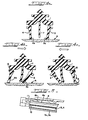
- the numeral 1 represents a blade body, the cross-sectional shape of which is roughly the shape of a five-painted star, and, at the top of this blade body 1, an engagement head 2 having a triangular cross-sectional shape is formed as a unified part of the blade body 1.
- the head 2 is utilized to attach the blade to a wiper arm 8, and the shape of this engagement head 2 may be changed as appropriate to match the type of wiper arm 8, as will be described later.
- the numerals 3 and 4 are a pair of opposing wiper blades, and each of these two blades 3 and 4 is connected at its base (the upper end as seen in Fig. 2) to the blade body 1 in the vicinity of one of the opposite side edge of the lower surface of the blade body 1.
- a connecting piece 5 is provided to connect the blades 3 and 4 to the body 1, each piece 5 having an angular cross-sectional shape such as to both facilitate the inward flexure ana to ninaer cne oucwara riexcre of the associated blade.
- a projection 3a and 4a projects laterally outwardly from the longitudinal direction of the blade.
- a wiping piece 3b and 4b which has a triangular cross-sectional shape and extends in the longitudinal direction, in such a manner that it is in contact with the surface of the glass A during the swinging or wiping motion of the blade body 1.
- each blade preferably extends laterally inwardly in the direction of a center rib 7 but it could instead extend laterally outwardly away from the rib 7.
- the drawings show laterally inward wiping pieces 3b and 4b and they are more efficient in wiping water as compared with laterally outward wiping pieces. Note that it is possible for these wiping pieces 3b and 4b to have a cross-sectional shape other than the triangular one shown in the drawing.
- the numerals 3c and 4c indicate laterally outward projections having a triangular cross-sectional shape, and these projections 3c and 4c are provided either continuously or intermittently in the longitudinal direction along the outward sides (near the bottom edges) of each of the two opposing blades 3 and 4. These projections 3c and 4c precede the outward surfacea of th* bladea 3 and 4, which hand inward during the swinging movement of the wiper, in their contact with the glass surface A, thus making it possible for the blades 3 and 4 to slide smoothly across the surface of the glass.
- a thin center rib 7 extends down from the center of the blade body 1 between the blades 3 and 4, and it is designed in such a manner that its bottom edge does not extend down quite as far as the bottom edges of the two opposing blades 3 and 4.
- long parallel grooves 7a are formed in the longitudinal direction on both sides of the center rib 7 in diagonally alternating positions, as shown in Fig. 2.
- the grooves. 7a on one side of the rib 7 are vertically offset from the grooves 7a on the other side.
- the numeral 8 represents the wiper arm, and it includes a pair of retainers 8a (see Fig. 3), between which the engagement head 2 of the blade body 1 is inserted in such a manner that the lower part of the engagement head 2 is held between the retainers 8a.
- a number of engagement pawls 8b are provided at specified intervals along the longitudinal direction of the wiper arm 8, both ends of which are secured to the retainers 8a. The blade body 1 is thus mounted to the wiper arm 8 by sliding one end of the blade 1 in from one end of the wiper arm 8.
- Fig. 3 shows a perspective view of one end (the upper part during operation) of the wiper.
- 10 is a pair of washer fluid spray tubes, and each of these washer fluid spray tubes 10 is routed along one of the lateral channels la on either side of the blade body 1.
- These washer fluid spray tubes 10 are bent in a U shape in such a manner that the fluid spray holes are directed into the spaces between the two opposing blades 3 and 4 and the center rib 7.
- the ends of this pair of washer fluid spray tubes 10 are secured by a securing fixture 11.
- the other ends of the washer fluid spray tubes 10 are connected to the customary washer tube (not shown) from the washer fluid tank via a branching tube at one end of the blade body 1.
- Figs. 4a through 4c illustrate the operation of the blade.
- the wiping pieces 3b and 4b are either very slightly separated from the glass surface A or, if they are in contact, the force pressing them against the glass surface A is extremely weak.
- the wiping pieces 3b and 4b are less affected by the heating up (summer season) and the freezing (winter season) of the glass surface A, and are consequently less subjected to deterioration.
- the blade 3 and the blade 4 on the side toward which the wiper is moving bends considerably in the opposite direction, causing the wiping piece 3b and 4b on the inside of the edge of that blade 3 and 4 to come in contact with the center rib 7, and also causing the outside of the bottom edge of that blade 3 and 4 and the projection 3c and 4c to be in contact with the glass surface A while the wiper moves, thus wiping the rainwater, etc., from the glass surface A.
- the blade 4 (or 3) on the opposite side bends slightly less, so that the wiping piece 4b (or 3b) at its edge is in contact with the glass surface A, thus wiping away any rainwater, etc., which the first blade 3 (or 4) failed to wipe away.
- Fig. 5 shows a wiper blade similar to that described above, supported by a different design of a supporting wiper arm.
- a wiper blade according to this invention has a number of advantages. Because the center rib is provided between the two opposing blades, the two blades are kept separate during operation of the wiper, so that after one of the blades wipes away the rainwater, etc., the other blade will also wipe away any rainwater, etc., which still remains, thus preventing any rainwater, etc., from remaining on the glass surface.
- a wiping piece 3b and 4b projects from the inside of the edge of each of the two opposing blades, it is not necessary to cut with extreme accuracy to make certain that the corner angles of the blade edges are exactly 90° when, for example, a pair of blades are formed together with their edges
- the wiper blade is constructed in such a manner that spaces are formed between the two opposing blades and the center rib, the mounting of spray tubes to spray washer fluid into these spaces not only allows the washer fluid to wash away any dust, etc., from between the blades, but, because the washer fluid will thus be sprayed only on the parts of the glass surface which are being wiped, smaller amounts of washer fluid can be put to more effective use and the washer fluid will not soil other parts of the vehicle.
- the blade body By forming the blade body so that its cross-sectional shape is roughly the shape of a five-pointed star, and thus forming lateral channels of each side of the blade body, when the wiper blade is mounted to the wiper arm, differences in the type of wiper arm or in the mounting method will not affect the wiper biaue. moreover, oevause une wiper biaue to nelo securely by the wiper arm, the appropriate position can be maintained, and also, because the retainers of the wiper arm are in secure contact with the top of the blade body and support the blade body, the wiper blade will always be kept at a right angle to the glass surface, regardless of the wiping position, thus ensuring consistent wiping performance.
Landscapes
- Engineering & Computer Science (AREA)
- Water Supply & Treatment (AREA)
- Mechanical Engineering (AREA)
- Window Of Vehicle (AREA)
- Pivots And Pivotal Connections (AREA)
- Vehicle Cleaning, Maintenance, Repair, Refitting, And Outriggers (AREA)
Applications Claiming Priority (2)
| Application Number | Priority Date | Filing Date | Title |
|---|---|---|---|
| JP135446/85 | 1985-06-20 | ||
| JP60135446A JPS61295157A (ja) | 1985-06-20 | 1985-06-20 | ワイパ−プレ−ド |
Publications (2)
| Publication Number | Publication Date |
|---|---|
| EP0206773A2 true EP0206773A2 (fr) | 1986-12-30 |
| EP0206773A3 EP0206773A3 (fr) | 1988-07-06 |
Family
ID=15151908
Family Applications (1)
| Application Number | Title | Priority Date | Filing Date |
|---|---|---|---|
| EP86304735A Withdrawn EP0206773A3 (fr) | 1985-06-20 | 1986-06-19 | Lame d'essuyage |
Country Status (3)
| Country | Link |
|---|---|
| US (1) | US4723336A (fr) |
| EP (1) | EP0206773A3 (fr) |
| JP (1) | JPS61295157A (fr) |
Families Citing this family (17)
| Publication number | Priority date | Publication date | Assignee | Title |
|---|---|---|---|---|
| US5044042A (en) * | 1989-10-27 | 1991-09-03 | The Anderson Company | Windshield wiper blade with dual wiping edges |
| FR2656846B1 (fr) * | 1990-01-11 | 1992-04-10 | Valeo Systemes Dessuyage | Lame d'essuie-glace et balai d'essuie-glace comportant une telle lame. |
| JP2588688Y2 (ja) * | 1991-08-06 | 1999-01-13 | 株式会社 トカチ企画 | ワイパーブレード |
| USD349082S (en) | 1993-08-30 | 1994-07-26 | Brabender Earl E | Combined windshield wiper and washer |
| SE9501810D0 (sv) * | 1995-05-16 | 1995-05-16 | Electrolux Ab | Skrapa av elastiskt material |
| JP2000509351A (ja) * | 1996-10-29 | 2000-07-25 | ジーゲル マーケティング コンサルティング ゲーエムベーハー | ウインドーワイパーのブレード |
| US6618895B1 (en) | 2000-08-02 | 2003-09-16 | Albert J. James | Water-diverting windshield wiper blades |
| US7555806B1 (en) | 2000-08-02 | 2009-07-07 | James Albert J | Water-diverting windshield wiper blades |
| WO2003031240A1 (fr) * | 2001-10-03 | 2003-04-17 | Masahiro Ishihara | Caoutchouc d'essuie-glace a plusieurs lames |
| US7627924B2 (en) * | 2006-06-13 | 2009-12-08 | Don Vamer | Compound water-wiper apparatus |
| FR2952883B1 (fr) * | 2009-11-23 | 2012-12-14 | Peugeot Citroen Automobiles Sa | Balai d'essuie glace integrant un conduit de liquide de lavage |
| DE102014214578A1 (de) * | 2014-07-24 | 2016-01-28 | Robert Bosch Gmbh | Wischlippe für eine Scheibenwischvorrichtung |
| EP3204268B1 (fr) * | 2014-10-09 | 2021-06-16 | Nelson and Nelson Enterprises, LLC | Essuie-glace à mouvement en va-et-vient |
| WO2016057968A1 (fr) * | 2014-10-09 | 2016-04-14 | Nelson James Q | Essuie-glace à mouvement en va-et-vient |
| CN108463382B (zh) * | 2016-06-02 | 2021-08-24 | 朴世宪 | 汽车用雨刷片 |
| US11142167B2 (en) * | 2019-01-07 | 2021-10-12 | Steam Tech, Llc | Wiper blade with directionally differentiated motion |
| CN110639853A (zh) * | 2019-11-13 | 2020-01-03 | 亚杰科技(江苏)有限公司 | 一种粉尘刮刮器 |
Family Cites Families (17)
| Publication number | Priority date | Publication date | Assignee | Title |
|---|---|---|---|---|
| BE627861A (fr) * | ||||
| GB461560A (en) * | 1934-12-01 | 1937-02-15 | Getefo | Improvements in or relating to packing strips and the like |
| DE711911C (de) * | 1935-03-10 | 1941-10-08 | Clemens A Voigt | Scheibenwischerleiste fuer Kraftfahrzeuge |
| US2080129A (en) * | 1935-12-24 | 1937-05-11 | Gulotta Charles | Windshield squeegee |
| FR1079609A (fr) * | 1952-06-28 | 1954-12-01 | Bosch Gmbh Robert | Essuie-glace, en particulier pour automobiles |
| FR1232978A (fr) * | 1958-04-01 | 1960-10-12 | Trico Folberth Ltd | Essuie-glace |
| US3116510A (en) * | 1963-05-20 | 1964-01-07 | Trico Products Corp | Windshield wiper |
| CH427534A (de) * | 1965-10-25 | 1966-12-31 | Ring Lars Magnus | Scheibenwischer mit Wascheinrichtung an einem Fahrzeug |
| FR1497802A (fr) * | 1966-10-25 | 1967-10-13 | Essuie-glace à dispositif de lavage pour véhicules automobiles | |
| DE2026102A1 (de) * | 1970-05-27 | 1971-12-16 | Alazet, Jean, Perpignan, Pyrenees Orientales (Frankreich) | Abstreifer für einen Scheibenwischer |
| FR2373426A1 (fr) * | 1976-12-10 | 1978-07-07 | Heuliez Sa Louis | Balai d'essuie-glace |
| US4339839A (en) * | 1979-03-23 | 1982-07-20 | Knights, Brooks And Partners Limited | Windscreen wipers |
| DE2917183A1 (de) * | 1979-04-27 | 1980-11-06 | Siemens Ag | Reinigungseinrichtung fuer optisch transparente grenzflaechen |
| DE2933363A1 (de) * | 1979-08-17 | 1981-03-26 | Wolfgang 25524 Breitenburg Priesemuth | Scheibenwischer |
| DE3134083A1 (de) * | 1981-08-28 | 1983-03-10 | Wolfram 7891 Berau Paulus | Einrichtung zur reinigung und/oder enteisung von aussenscheiben, insbesondere fuer kraftfahrzeuge |
| WO1983002756A1 (fr) * | 1982-02-09 | 1983-08-18 | Alexander Szucs | Ameliorations relatives a des assemblages d'essuie-glaces |
| DE8511624U1 (de) * | 1985-04-19 | 1986-08-21 | Robert Bosch Gmbh, 7000 Stuttgart | Wischblatt zum Reinigen von Kraftfahrzeugscheiben |
-
1985
- 1985-06-20 JP JP60135446A patent/JPS61295157A/ja active Granted
-
1986
- 1986-06-12 US US06/873,599 patent/US4723336A/en not_active Expired - Fee Related
- 1986-06-19 EP EP86304735A patent/EP0206773A3/fr not_active Withdrawn
Also Published As
| Publication number | Publication date |
|---|---|
| US4723336A (en) | 1988-02-09 |
| EP0206773A3 (fr) | 1988-07-06 |
| JPH0369737B2 (fr) | 1991-11-05 |
| JPS61295157A (ja) | 1986-12-25 |
Similar Documents
| Publication | Publication Date | Title |
|---|---|---|
| US4723336A (en) | Wiper blade | |
| EP0783998B1 (fr) | Essuie-glace | |
| US8782845B2 (en) | Wiper blade comprising a support mount, an internal verterbra and a connecting element | |
| US20030074763A1 (en) | Wiper device for cleaning the glass panes of vehicles, especially automobiles | |
| CN1974280B (zh) | 刮水片 | |
| MXPA04009085A (es) | Dispositivo limpiaparabrisas con hoja plana y brazo de limpiaparabrisas. | |
| US20150151718A1 (en) | Wiper coupler assembly and wiper assembly incorporating same | |
| WO2008051483A2 (fr) | Système d'essuie-glace comprenant un bras d'essuie-glace de style broche et assemblage d'essuie-glace | |
| EP2401181A1 (fr) | Ensemble essuie-glace pour pare-brise avec profil aérodynamique optimisé | |
| WO2012071401A2 (fr) | Ensemble essuie-glace à balai profilé qui comprend un bouchon d'extrémité autobloquant | |
| KR19980063590A (ko) | 자동차용 윈드 쉴드 와이퍼 | |
| CA2174030A1 (fr) | Essuie-glace d'hiver avec raclette incurvee souple | |
| US7735184B2 (en) | Wiper blade for cleaning glass or polymeric windshields | |
| JP3653874B2 (ja) | ウインター用ワイパーブレードにおけるバーティブラ | |
| CA1056561A (fr) | Attache incorporee pour essuie-glace | |
| JPH03504588A (ja) | フロントガラスワイパー | |
| GB2151914A (en) | Wiper blade | |
| EP1647459B1 (fr) | Un bras d'essuie-glace | |
| EP3517375A1 (fr) | Système d'essuie-glace comprenant un élément de pulvérisation de liquide de lavage | |
| KR102461203B1 (ko) | 와이퍼 장치 | |
| US20250360893A1 (en) | Wiper-blade including textured surface | |
| CN212685489U (zh) | 一种紧固性好的汽车用雨刮器 | |
| EP2193056A1 (fr) | Dispositif essuie-glace | |
| JPH07215174A (ja) | ワイパ−用リップと該リップを使用したワイパ− | |
| RU2173643C1 (ru) | Щетка стеклоочистителя для транспортного средства |
Legal Events
| Date | Code | Title | Description |
|---|---|---|---|
| PUAI | Public reference made under article 153(3) epc to a published international application that has entered the european phase |
Free format text: ORIGINAL CODE: 0009012 |
|
| AK | Designated contracting states |
Kind code of ref document: A2 Designated state(s): DE FR GB IT SE |
|
| PUAL | Search report despatched |
Free format text: ORIGINAL CODE: 0009013 |
|
| AK | Designated contracting states |
Kind code of ref document: A3 Designated state(s): DE FR GB IT SE |
|
| STAA | Information on the status of an ep patent application or granted ep patent |
Free format text: STATUS: THE APPLICATION IS DEEMED TO BE WITHDRAWN |
|
| 18D | Application deemed to be withdrawn |
Effective date: 19890107 |
|
| RIN1 | Information on inventor provided before grant (corrected) |
Inventor name: NAKAYAMA, YASUZI |