EP0206943A2 - Faseroptische Kupplungsvorrichtung - Google Patents
Faseroptische Kupplungsvorrichtung Download PDFInfo
- Publication number
- EP0206943A2 EP0206943A2 EP86401372A EP86401372A EP0206943A2 EP 0206943 A2 EP0206943 A2 EP 0206943A2 EP 86401372 A EP86401372 A EP 86401372A EP 86401372 A EP86401372 A EP 86401372A EP 0206943 A2 EP0206943 A2 EP 0206943A2
- Authority
- EP
- European Patent Office
- Prior art keywords
- lens
- housing
- disposed
- optical fiber
- high pressure
- Prior art date
- Legal status (The legal status is an assumption and is not a legal conclusion. Google has not performed a legal analysis and makes no representation as to the accuracy of the status listed.)
- Withdrawn
Links
Images
Classifications
-
- E—FIXED CONSTRUCTIONS
- E21—EARTH OR ROCK DRILLING; MINING
- E21B—EARTH OR ROCK DRILLING; OBTAINING OIL, GAS, WATER, SOLUBLE OR MELTABLE MATERIALS OR A SLURRY OF MINERALS FROM WELLS
- E21B47/00—Survey of boreholes or wells
- E21B47/12—Means for transmitting measuring-signals or control signals from the well to the surface, or from the surface to the well, e.g. for logging while drilling
- E21B47/13—Means for transmitting measuring-signals or control signals from the well to the surface, or from the surface to the well, e.g. for logging while drilling by electromagnetic energy, e.g. radio frequency
- E21B47/135—Means for transmitting measuring-signals or control signals from the well to the surface, or from the surface to the well, e.g. for logging while drilling by electromagnetic energy, e.g. radio frequency using light waves, e.g. infrared or ultraviolet waves
-
- G—PHYSICS
- G02—OPTICS
- G02B—OPTICAL ELEMENTS, SYSTEMS OR APPARATUS
- G02B6/00—Light guides; Structural details of arrangements comprising light guides and other optical elements, e.g. couplings
- G02B6/24—Coupling light guides
- G02B6/26—Optical coupling means
- G02B6/32—Optical coupling means having lens focusing means positioned between opposed fibre ends
-
- G—PHYSICS
- G02—OPTICS
- G02B—OPTICAL ELEMENTS, SYSTEMS OR APPARATUS
- G02B6/00—Light guides; Structural details of arrangements comprising light guides and other optical elements, e.g. couplings
- G02B6/24—Coupling light guides
- G02B6/36—Mechanical coupling means
- G02B6/38—Mechanical coupling means having fibre to fibre mating means
- G02B6/3807—Dismountable connectors, i.e. comprising plugs
- G02B6/381—Dismountable connectors, i.e. comprising plugs of the ferrule type, e.g. fibre ends embedded in ferrules, connecting a pair of fibres
- G02B6/3816—Dismountable connectors, i.e. comprising plugs of the ferrule type, e.g. fibre ends embedded in ferrules, connecting a pair of fibres for use under water, high pressure connectors
-
- G—PHYSICS
- G02—OPTICS
- G02B—OPTICAL ELEMENTS, SYSTEMS OR APPARATUS
- G02B6/00—Light guides; Structural details of arrangements comprising light guides and other optical elements, e.g. couplings
- G02B6/24—Coupling light guides
- G02B6/36—Mechanical coupling means
- G02B6/38—Mechanical coupling means having fibre to fibre mating means
- G02B6/3807—Dismountable connectors, i.e. comprising plugs
- G02B6/3897—Connectors fixed to housings, casing, frames or circuit boards
-
- G—PHYSICS
- G02—OPTICS
- G02B—OPTICAL ELEMENTS, SYSTEMS OR APPARATUS
- G02B6/00—Light guides; Structural details of arrangements comprising light guides and other optical elements, e.g. couplings
- G02B6/44—Mechanical structures for providing tensile strength and external protection for fibres, e.g. optical transmission cables
- G02B6/4401—Optical cables
- G02B6/4415—Cables for special applications
- G02B6/4427—Pressure resistant cables, e.g. undersea cables
- G02B6/4428—Penetrator systems in pressure-resistant devices
-
- G—PHYSICS
- G02—OPTICS
- G02B—OPTICAL ELEMENTS, SYSTEMS OR APPARATUS
- G02B6/00—Light guides; Structural details of arrangements comprising light guides and other optical elements, e.g. couplings
- G02B6/24—Coupling light guides
- G02B6/36—Mechanical coupling means
- G02B6/38—Mechanical coupling means having fibre to fibre mating means
- G02B6/3807—Dismountable connectors, i.e. comprising plugs
- G02B6/3833—Details of mounting fibres in ferrules; Assembly methods; Manufacture
Definitions
- a connector assembly for mechanically and optically connecting the optical fiber disposed within the well-logging tool with the optical fiber disposed within the borehole provide a complete and total sealing therebetween, so that the high pressure and/or temperature fluids of the borehole do not enter the interior of the well-logging tool. It is also important that the connector assembly be readily demountable and allow quick and easy assembly and disassembly thereof with respect to the well-logging tool.
- the foregoing advantages have been achieved through the present connector assembly for mechanically and optically associating a first optical fiber, exposed to high pressure and/or temperature fluids, with a second optical fiber, disposed within a body having low pressure conditions therein.
- a further feature of the present invention is that the housing may have an interior annular flange member disposed proximate the second end of the housing, the flange member having an opening extending therethrough; the at least one transparent bulkhead is a rigid transparent window, hermetically sealed with respect to the annular flange member and the housing passageway; and the at least one transparent bulkhead may be disposed between the interior annular flange member and the first optical fiber.
- the connector assembly of the present invention when compared with previously proposed prior art connector assemblies, has the advantages of: providing low loss optical couplings, providing a hermetic construction whereby the transmission of high pressure and/or temperature fluids into a well-logging tool is prevented; is fully demountable; and allowing repeated connection and disconnection of the optical fibers.
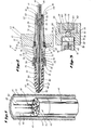
- Body 50 may comprise a conventional well-logging head 43, as previously described, and well-logging head 43 may have one or more openings 51 therein (FIGS. 1 and 2) which openings 51 provide access through well-logging head 43 to the interior of the well-logging tool 44.
- the connector assembly 40 further generally comprises at least one transparent bulkhead 52, sealingly disposed within the housing 49 and associated with the first optical fiber 45. Bulkhead 52 is disposed between the first and second optical fibers 45, 48.
- the high pressure connector member 46 may be an elongate, generally tubular member 54 having the first optical fiber 45 disposed therein and extending along the length of the tubular member 54.
- a portion of the high pressure connector member 46 has a sealing means 55 associated therewith, whereby the high pressure connector member 46 is sealingly received within the housing 49 in a non-fluid transmitting relationship with respect to the housing 49.
- Sealing means 55 may be an elastomeric O-ring seal, or any other type of suitable seal; and preferably two O-ring seals 55' are disposed within an outer annular groove 56 formed in the outer surface of high pressure connector member 46. As seen in FIG. 2, O-rings 55' engage in a sealing manner with an interior surface of housing 49.
- housing 49 may be an elongate, generally tubular member 57 having a passageway 58 extending throughout the length of the tubular member 57 and having first and second ends 59, 60.
- first end 59 is adapted to receive the high pressure connector member 46 and the second end 60 is adapted to receive the low pressure connector member 47.
- the at least one transparent bulkhead 52 is sealingly disposed, as will be hereinafter described in greater detail, proximate the second end 60 of the housing 49.
- Housing 49 may be adapted to be releaseably and sealingly disposed with respect to the body 50, or well-logging head 43, in any suitable fashion; however, housing 49 is preferably threadably disposed within well-logging head 43, as by mating threads 61 formed on housing 49 and within opening 51 of well-logging head 43. Additionally, a sealing means 62, or O-rings 63, may be provided between body 50 and housing 49, as by disposing O-rings 63 within an outer annular groove 64, formed in the outer surface of housing 49. Of course, any other suitable sealing means 62, other than O-rings 63 could be utilized, such as mating, water-tight screw threads, which insure that housing 49 is sealingly disposed with respect to the body 50, or well-logging head 43.
- seal means 65 comprises a generally tubular shaped elastic member 68 which tightly conforms to an exterior surface of the portion 66 of the high pressure connector member 46 which extends outwardly from the housing 49, and which elastic member also tightly conforms to an exterior surface portion 69 of the first optical fiber 45 which extends outwardly from the high pressure connector member 46.
- Seal means 65 could be manufactured of any suitable elastomeric material having the requisite sealing characteristics, as well as the necessary strength and durability characteristics to withstand exposure to the high pressure and/or temperature fluids to which it is exposed.
- housing 49 and the high pressure connector member 46 may be manufactured of any suitable metallic material having the requisite strength and durability characteristics to withstand the high pressure and temperature conditions encountered in a borehole 41.
- housing 49 may include means for releaseably securing 70 the high pressure connector member 46 within the housing 49, the releaseable securing means 70 contacting the high pressure connector member 46 to compress it within the housing 49.
- the releaseable securing means 70 may comprise a threaded nut 71 which is engageable with the housing 49, as by mating threads 72, and is also engageable with the high pressure connector member 46, as by nut 71 engaging an annular rib 73 formed on the outer surface of high pressure connector member 46.
- jacketing material 82 associated with first optical fiber 45 may end proximate end 79 of high pressure connector member 46, whereby an unjacketed portion of first optical fiber 45 extends to the end 79 of high pressure connector member 46.
- the at least one transparent bulkhead 52 sealingly abuts against interior annular flange member 90 and passageway 58 of housing 49.
- the second end 60 of housing 49 may comprise a separate end portion 93 which is preferably welded, as at 94, to the other portion 95 of housing 49.
- end portion 93 could be press-fitted into portion 95 of housing 49, or alternatively, threadedly received into portion 95 of housing 49.
- the at least one ball lens 53 is disposed proximate the opening 91 in the interior annular flange member 90 and between the at least one transparent bulkhead 52 and the second optical fiber 48 in a light transmitting relationship with respect to the first and second optical fibers 45, 48.
- Low pressure connector member 47 may comprise a generally elongate tubular member 96 having the second optical fiber 48 disposed therein. Low pressure connector member 47 may be merely inserted into the passageway 58 at the second end 60 of housing 49; however, low pressure connector member 47 preferably has a lens spacer member 97 associated therewith. Lens spacer member 97 is disposed between the at least one ball lens 53 and the second optical fiber 48; and lens spacer member 97 and low pressure connector member 47 are received in the passageway 58 at the second end 60 of housing 49.
- the first end 99 of the lens spacer member 97 may also include an alignment surface 102, as formed by a tapered countersunk opening 103, which alignment surface 102 engages the at least one ball lens 53 to align the ball lens 53 with the opening 101 in the first end 99 of the lens spacer member 97, which in turn forces the ball lens 53 to slightly contact the transparent bulkhead 52.
- Lens spacer member 97 also serves to precisely space the second optical fiber 48 from the ball lens 53.
- Lens spacer member 97 could be formed in one or more pieces; however, it is preferably a single tubular cup-shaped member 98 which is press-fitted within passageway 58 at the second end 60 of housing 49.
- the second optical fiber 48 may be held in place within the low pressure connector member 47 as by a spring-loaded pin (not shown), or any other suitable means which insures that the second optical fiber 48 does not extend outwardly of the tubular member 96, so as to not contact the ball lens 53.
- the connector assembly 40 in accordance with the present invention, is readily demountable from either side of body 50, or well-logging head 43, and may be easily assembled and disassembled as necessary.
- the connector assembly 40 first has the at least one transparent bulkhead 52 hermetically sealed within housing 49, and thereafter ball lens 53 is placed in opening 91 in the interior annular flange member 90. Ball lens 53 is then aligned by inserting the lens spacer member 97 into the passageway 58 at the second end 60 of housing 49, as previously described. Housing 49, including transparent bulkhead 52, ball lens 53, and lens spacer member 97 may then be sealingly disposed within body 50, or well-logging head 43, as previously described. Thereafter, the high pressure and low pressure connector members 46 and 47 are assembled as previously described, including the placement of seal means 65 about high pressure connector member 46 and the first optical fiber 45.
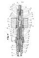
- FIG. 4 another embodiment of a connector assembly 40', in accordance with the present invention will be described.
- Elements of connector assembly 40' bear the same reference numerals as the elements of the embodiment of connector assembly 40 described in connection with FIGS. 2 and 3, when such elements are the same, or substantially the same, as those previously described, and description of such elements will not be repeated hereinafter.
- Elements of connector assembly 40' differing from corresponding elements of connector assembly 40 have been numbered the same, but such reference numerals carry a prime (') designation.
- high pressure and low pressure connector members 46' and 47' of FIG. 4 differ from those previously described, but operate in substantially the same manner.
- high pressure connector member 46' is an elongate, generally tubular member 54' having the first optical fiber 45 disposed therein and extending along the length of the tubular member 54'. Additionally, as seen in FIG. 4, a portion of the first optical fiber 45 passes outwardly from tubular member 54' and into an auxiliary high pressure connector member 110.
- Auxiliary high pressure connector member 110 may be a generally elongate, tubular member 111 which receives the first optical fiber 45, having jacket 82 thereon. Member 111 may include an enlarged end portion 112 which is received within tubular member 54', and abuts against an inwardly extending ridge 113 formed in an end of tubular member 54'.
- High pressure connector member 46' is sealingly received within housing 49 in the same manner that high pressure connector member 46 is received within housing 49 via releaseable securing means 70 as previously described.
- the embodiment of connector assembly 40' of FIG. 4 utilizes at least one lens 53", or a cylindrical, rod-shaped lens 117, disposed within lens spacer member 97' proximate the second end 60 of housing 49.
- a suitable cylindrical, rod-shaped lens 117 is a lens sold by NSG America, Inc., under the trademark SELFOC C.
- Such lenses 117 may be either a collimating lens or a focusing lens. In the embodiment shown in FIG.
- the signals are then transmitted through the lens 118, whereby the light signals are collimated and made parallel, prior to passing through transparent bulkhead 52.
- the light, or optic, signals then enter lens 117, and are recollimated, or refocused, by lens 117 into the second optical fiber 48, and enter the electronic instrumentation (not shown) contained within the body 50, or well-logging head 43 of well-logging tool 44.
- connector assembly 40' when only utilizing one cylindrical, rod-shaped lens 117 would be identical to that previously described in connection with connector assembly 40 of FIGS. 2 and 3.
- cylindrical, rod-shaped lens 117 could be dispensed with and a single cylindrical, rod-shaped lens 118, of the focusing type would be disposed as shown in FIG. 4 and the second optical fiber 48 would be disposed in close proximity to opening 91, as by extending low pressure connector member 47' to end 99' of lens spacer member 98'.
Landscapes
- Physics & Mathematics (AREA)
- Engineering & Computer Science (AREA)
- General Physics & Mathematics (AREA)
- Optics & Photonics (AREA)
- Remote Sensing (AREA)
- Mining & Mineral Resources (AREA)
- Geology (AREA)
- Life Sciences & Earth Sciences (AREA)
- Environmental & Geological Engineering (AREA)
- Fluid Mechanics (AREA)
- Geophysics (AREA)
- Electromagnetism (AREA)
- General Life Sciences & Earth Sciences (AREA)
- Geochemistry & Mineralogy (AREA)
- Mechanical Coupling Of Light Guides (AREA)
- Optical Couplings Of Light Guides (AREA)
Applications Claiming Priority (2)
| Application Number | Priority Date | Filing Date | Title |
|---|---|---|---|
| US06/748,257 US4759601A (en) | 1985-06-24 | 1985-06-24 | Fiber optic connector assembly |
| US748257 | 1985-06-24 |
Publications (2)
| Publication Number | Publication Date |
|---|---|
| EP0206943A2 true EP0206943A2 (de) | 1986-12-30 |
| EP0206943A3 EP0206943A3 (de) | 1987-10-28 |
Family
ID=25008681
Family Applications (1)
| Application Number | Title | Priority Date | Filing Date |
|---|---|---|---|
| EP86401372A Withdrawn EP0206943A3 (de) | 1985-06-24 | 1986-06-23 | Faseroptische Kupplungsvorrichtung |
Country Status (3)
| Country | Link |
|---|---|
| US (1) | US4759601A (de) |
| EP (1) | EP0206943A3 (de) |
| CA (1) | CA1257794A (de) |
Cited By (10)
| Publication number | Priority date | Publication date | Assignee | Title |
|---|---|---|---|---|
| FR2639720A1 (fr) * | 1988-11-28 | 1990-06-01 | Commissariat Energie Atomique | Passage etanche pour fibres optiques |
| DE3919531A1 (de) * | 1989-06-15 | 1990-12-20 | Ant Nachrichtentech | Formstueck fuer einen lichtwellenleiterstecker zur aufnahme eines oder mehrerer lichtwellenleiter |
| WO1996007944A1 (en) * | 1994-09-08 | 1996-03-14 | Holec Projects B.V. | Lens connector for optical through-connection of light guides |
| WO2007009676A1 (en) * | 2005-07-19 | 2007-01-25 | Gigacom Holding Ab | Optical assembly for repetitive coupling and uncoupling |
| WO2008030754A1 (en) * | 2006-09-06 | 2008-03-13 | Baker Hughes Incorporated | Optical wet connect |
| US7736067B2 (en) | 2008-10-10 | 2010-06-15 | Schlumberger Technology Corporation | Fiber optic seal |
| WO2015082050A1 (de) * | 2013-12-06 | 2015-06-11 | Diehl Metering Systems Gmbh | Ankopplungsvorrichtung für eine zählereinrichtung, zähleranordnung und verfahren zur kommunikation mit einer zählereinrichtung |
| EP3182182A1 (de) * | 2015-12-15 | 2017-06-21 | Radiall S.A. | Vorrichtung zur kopplung von zwei glasfasern zur verwendung in verbindern |
| WO2017103381A1 (fr) * | 2015-12-16 | 2017-06-22 | Commissariat A L'energie Atomique Et Aux Energies Alternatives | Dispositif pour la stimulation optique du cerveau au moyen d'une fibre optique |
| CN108535810A (zh) * | 2017-03-02 | 2018-09-14 | 肖特股份有限公司 | 用于光导的套圈、具有套圈的组件及其制造方法 |
Families Citing this family (32)
| Publication number | Priority date | Publication date | Assignee | Title |
|---|---|---|---|---|
| NL8901821A (nl) * | 1988-08-25 | 1990-03-16 | Philips Nv | Reflectiearm bollensconnectordeel. |
| US4859021A (en) * | 1988-09-20 | 1989-08-22 | Hughes Aircraft Company | Hermetic feedthrough connector for fiber optic transmission |
| US4891640A (en) * | 1988-11-03 | 1990-01-02 | Halliburton Logging Services, Inc. | High temperature and pressure fiber optic feedthrough for borehole usage |
| GB2228340B (en) * | 1989-02-16 | 1993-02-10 | Stc Plc | Hermetic gland for optical fibres |
| US5033808A (en) * | 1990-05-08 | 1991-07-23 | Halliburton Logging Services, Inc. | Quick disconnect fiber optic feedthrough for well borehole usage |
| US5315684A (en) * | 1991-06-12 | 1994-05-24 | John Mezzalingua Assoc. Inc. | Fiber optic cable end connector |
| SE9102851L (sv) * | 1991-06-17 | 1992-12-18 | Stratos Connectors Ab | Anordning foer optisk anslutning av ett optiskt element till en lins |
| US5113464A (en) * | 1991-06-24 | 1992-05-12 | Hughes Aircraft Company | Method of producing an optical fiber terminus for high temperature use |
| GB2263557A (en) * | 1992-01-16 | 1993-07-28 | Itt Ind Ltd | Lens optical fibre connectors |
| US5283853A (en) * | 1992-02-14 | 1994-02-01 | John Mezzalingua Assoc. Inc. | Fiber optic end connector |
| US5210815A (en) * | 1992-04-09 | 1993-05-11 | G & H Technology, Inc. | Hermetically sealed optical fiber feedthrough |
| US5253321A (en) * | 1992-05-18 | 1993-10-12 | Texaco Inc. | Means for inserting fiber optic probes into pressurized vessels |
| US5450519A (en) * | 1994-05-02 | 1995-09-12 | The United States Of America As Represented By The Secretary Of The Navy | Fiber optic coupler assembly |
| US6163642A (en) * | 1996-02-12 | 2000-12-19 | Medallion Technology, Llc | Optical transmitter/receiver interface for sealed environments and method of using same |
| US5680494A (en) * | 1996-05-16 | 1997-10-21 | Bell Atlantic Network Services, Inc. | FC-type optical fiber connector adapter |
| US5812728A (en) * | 1996-10-04 | 1998-09-22 | Mcdonnell Douglas Corporation | Terminus adapter for fiber optic cables |
| US6349160B2 (en) | 1998-07-24 | 2002-02-19 | Aurora Biosciences Corporation | Detector and screening device for ion channels |
| US6608671B2 (en) * | 1998-07-17 | 2003-08-19 | Vertex Pharmaceuticals (San Diego) Llc | Detector and screening device for ion channels |
| US6351593B1 (en) | 1998-11-30 | 2002-02-26 | Three E Laboratories, Inc. | Hermetically sealed connectors and feed-throughs for fiber optic cables and method for effecting hermetic seals for such cables |
| US6321021B1 (en) * | 1999-07-12 | 2001-11-20 | Ocean Design, Inc. | End seal assembly for tubular conduit |
| US6685361B1 (en) | 2000-06-15 | 2004-02-03 | Weatherford/Lamb, Inc. | Fiber optic cable connectors for downhole applications |
| US6666274B2 (en) * | 2002-05-15 | 2003-12-23 | Sunstone Corporation | Tubing containing electrical wiring insert |
| US7226090B2 (en) * | 2003-08-01 | 2007-06-05 | Sunstone Corporation | Rod and tubing joint of multiple orientations containing electrical wiring |
| US7390032B2 (en) * | 2003-08-01 | 2008-06-24 | Sonstone Corporation | Tubing joint of multiple orientations containing electrical wiring |
| US7344316B2 (en) * | 2004-11-10 | 2008-03-18 | Tronic Limited | Connector |
| GB2420184A (en) * | 2004-11-10 | 2006-05-17 | Tronic Ltd | Optic fibre connector with interengaging parts for underwater use |
| US20080001775A1 (en) * | 2006-06-30 | 2008-01-03 | Baker Hughes Incorporated | Apparatus and method for memory dump and/or communication for mwd/lwd tools |
| NO327623B1 (no) * | 2007-07-11 | 2009-09-07 | Bennex As | Subsea fiberoptisk penetrator |
| CN101551491B (zh) * | 2009-04-24 | 2010-05-12 | 中国科学院电工研究所 | 低温下密封光纤的装置 |
| US20110235981A1 (en) * | 2010-03-29 | 2011-09-29 | Schlumberger Technology Corporation | Connector apparatus for downhole tool |
| EP3644105B1 (de) * | 2014-06-23 | 2026-02-11 | CommScope Connectivity Belgium BVBA | Glasfaserverbindungssystem mit schnellkupplungsmechanismus |
| BR112016030752B1 (pt) * | 2014-07-07 | 2022-09-06 | Shell Internationale Research Maatschappij B.V. | Sistema e método para interconectar opticamente cabos de fibra óptica em uma instalação de produção de fluido de hidrocarboneto |
Family Cites Families (12)
| Publication number | Priority date | Publication date | Assignee | Title |
|---|---|---|---|---|
| US3825320A (en) * | 1973-03-02 | 1974-07-23 | Us Navy | High-pressure optical bulkhead penetrator |
| US3914015A (en) * | 1974-10-15 | 1975-10-21 | Itt | Fiber optic connector and assembly method |
| US3963323A (en) * | 1974-12-23 | 1976-06-15 | International Telephone And Telegraph Corporation | Fiber optic connector with protective cable sleeves |
| US4204743A (en) * | 1976-06-21 | 1980-05-27 | U.S. Philips Corporation | Connector for coupling optical fibers to an emitter or receiver of luminous energy |
| US4222629A (en) * | 1978-03-27 | 1980-09-16 | Sperry Corporation | Fiber optic connector assembly |
| NL7806829A (nl) * | 1978-06-26 | 1979-12-28 | Philips Nv | Snel losneembare koppeling voor lichtgeleidende vezels. |
| US4440469A (en) * | 1980-09-18 | 1984-04-03 | Amp Incorporated | Optical waveguide connector |
| US4398791A (en) * | 1981-02-09 | 1983-08-16 | Litton Systems, Inc. | Single channel optical slip ring |
| SE8202359L (sv) * | 1981-04-20 | 1982-10-21 | Malco | Anordning for inbordes inriktning av en optisk fiber och en kollimatorlins |
| GB2104752B (en) * | 1981-07-20 | 1986-02-19 | Chevron Res | Optical communication system for drill hole logging |
| JPS5897015A (ja) * | 1981-12-05 | 1983-06-09 | Kokusai Denshin Denwa Co Ltd <Kdd> | 水密型光フアイバコネクタ |
| US4666242A (en) * | 1984-06-21 | 1987-05-19 | Lockheed Corporation | Underwater electro-optical connector including cable terminal unit with electro-optical probe |
-
1985
- 1985-06-24 US US06/748,257 patent/US4759601A/en not_active Expired - Lifetime
-
1986
- 1986-06-23 CA CA000512157A patent/CA1257794A/en not_active Expired
- 1986-06-23 EP EP86401372A patent/EP0206943A3/de not_active Withdrawn
Cited By (25)
| Publication number | Priority date | Publication date | Assignee | Title |
|---|---|---|---|---|
| FR2639720A1 (fr) * | 1988-11-28 | 1990-06-01 | Commissariat Energie Atomique | Passage etanche pour fibres optiques |
| DE3919531A1 (de) * | 1989-06-15 | 1990-12-20 | Ant Nachrichtentech | Formstueck fuer einen lichtwellenleiterstecker zur aufnahme eines oder mehrerer lichtwellenleiter |
| WO1996007944A1 (en) * | 1994-09-08 | 1996-03-14 | Holec Projects B.V. | Lens connector for optical through-connection of light guides |
| NL9401466A (nl) * | 1994-09-08 | 1996-04-01 | Holec Projects Bv | Lensconnector voor het optisch doorverbinden van optische geleiders. |
| US5784512A (en) * | 1994-09-08 | 1998-07-21 | Holec Projects B.V. | Lens connector for optical through-connection of light guides |
| WO2007009676A1 (en) * | 2005-07-19 | 2007-01-25 | Gigacom Holding Ab | Optical assembly for repetitive coupling and uncoupling |
| US9791632B2 (en) | 2005-07-19 | 2017-10-17 | Gigacom Interconnect Ab | Optical assembly |
| EP2757397A1 (de) * | 2005-07-19 | 2014-07-23 | Gigacom Interconnect AB | Optische Baugruppe zur wiederholten Kopplung und Entkopplung |
| AU2007292448B2 (en) * | 2006-09-06 | 2011-12-08 | Baker Hughes Incorporated | Optical wet connect |
| NO341358B1 (no) * | 2006-09-06 | 2017-10-23 | Baker Hughes Inc | Kabelforbindelse og fremgangsmåte for opprettelse av en nedihullsforbindelse |
| GB2455018B (en) * | 2006-09-06 | 2010-12-22 | Baker Hughes Inc | Optical wet connect |
| EA014544B1 (ru) * | 2006-09-06 | 2010-12-30 | Бейкер Хьюз Инкорпорейтед | "мокрое" оптическое соединение |
| NO20090977L (no) * | 2006-09-06 | 2009-06-05 | Baker Hughes Inc | Kabelforbindelse og fremgangsmåte for opprettelse av en nedihullsforbindelse |
| CN101617100B (zh) * | 2006-09-06 | 2012-12-12 | 贝克休斯公司 | 光学湿连接 |
| GB2455018A (en) * | 2006-09-06 | 2009-06-03 | Baker Hughes Inc | Optical wet connect |
| WO2008030754A1 (en) * | 2006-09-06 | 2008-03-13 | Baker Hughes Incorporated | Optical wet connect |
| US7736067B2 (en) | 2008-10-10 | 2010-06-15 | Schlumberger Technology Corporation | Fiber optic seal |
| CN105793671A (zh) * | 2013-12-06 | 2016-07-20 | 代傲表计系统有限公司 | 用于计量装置的耦联设备、计量设备和用于与计量装置通信的方法 |
| WO2015082050A1 (de) * | 2013-12-06 | 2015-06-11 | Diehl Metering Systems Gmbh | Ankopplungsvorrichtung für eine zählereinrichtung, zähleranordnung und verfahren zur kommunikation mit einer zählereinrichtung |
| EP3182182A1 (de) * | 2015-12-15 | 2017-06-21 | Radiall S.A. | Vorrichtung zur kopplung von zwei glasfasern zur verwendung in verbindern |
| WO2017103381A1 (fr) * | 2015-12-16 | 2017-06-22 | Commissariat A L'energie Atomique Et Aux Energies Alternatives | Dispositif pour la stimulation optique du cerveau au moyen d'une fibre optique |
| FR3045390A1 (fr) * | 2015-12-16 | 2017-06-23 | Commissariat Energie Atomique | Dispositif pour la stimulation optique du cerveau au moyen d'une fibre optique |
| CN108472496A (zh) * | 2015-12-16 | 2018-08-31 | 原子能与替代能源委员会 | 用于经由光纤光学地刺激大脑的设备 |
| US11202922B2 (en) | 2015-12-16 | 2021-12-21 | Commissariat à l'Energie Atomique et aux Energies Alternatives | Device for optically stimulating the brain via an optical fiber |
| CN108535810A (zh) * | 2017-03-02 | 2018-09-14 | 肖特股份有限公司 | 用于光导的套圈、具有套圈的组件及其制造方法 |
Also Published As
| Publication number | Publication date |
|---|---|
| US4759601A (en) | 1988-07-26 |
| EP0206943A3 (de) | 1987-10-28 |
| CA1257794A (en) | 1989-07-25 |
Similar Documents
| Publication | Publication Date | Title |
|---|---|---|
| EP0206943A2 (de) | Faseroptische Kupplungsvorrichtung | |
| US5210815A (en) | Hermetically sealed optical fiber feedthrough | |
| US4682846A (en) | Hermetic high pressure fiber optic bulkhead penetrator | |
| US4544233A (en) | Underwater optical fiber connector | |
| US5396232A (en) | Transmitter device with two insulating couplings for use in a borehole | |
| US4891640A (en) | High temperature and pressure fiber optic feedthrough for borehole usage | |
| US4616900A (en) | Coaxial underwater electro-optical connector | |
| US3999837A (en) | Light transmitting fiber bundle connector | |
| US4666242A (en) | Underwater electro-optical connector including cable terminal unit with electro-optical probe | |
| US4469399A (en) | Method of making an undersea, high pressure bulkhead penetrator for use with fiber optic cables | |
| US4537457A (en) | Connector for providing electrical continuity across a threaded connection | |
| US4756595A (en) | Optical fiber connector for high pressure environments | |
| US7852232B2 (en) | Downhole tool adapted for telemetry | |
| US10527751B2 (en) | Downhole fluid properties optical analysis probe having a removable optical tip | |
| US4172212A (en) | Submarine housing for submarine cable system repeater components or the like | |
| US4593970A (en) | Fiber optic feedthrough module, and method of making same | |
| JPH03197902A (ja) | 光ファイバ用密封グランド及び光ファイバ用密封グランドを含む水中光ファイバ通信システム用海底中継器 | |
| AU637642B2 (en) | Sealing gland | |
| US4859021A (en) | Hermetic feedthrough connector for fiber optic transmission | |
| US8757892B1 (en) | Connector | |
| US5033808A (en) | Quick disconnect fiber optic feedthrough for well borehole usage | |
| US4396248A (en) | Connector for optical fibres | |
| US4690487A (en) | Hermetically sealed fiber optic connector | |
| US6043895A (en) | Radiation probe with flexible sleeve | |
| US20020106179A1 (en) | Light path |
Legal Events
| Date | Code | Title | Description |
|---|---|---|---|
| PUAI | Public reference made under article 153(3) epc to a published international application that has entered the european phase |
Free format text: ORIGINAL CODE: 0009012 |
|
| AK | Designated contracting states |
Kind code of ref document: A2 Designated state(s): DE FR GB IT NL |
|
| PUAL | Search report despatched |
Free format text: ORIGINAL CODE: 0009013 |
|
| RHK1 | Main classification (correction) |
Ipc: G02B 6/26 |
|
| AK | Designated contracting states |
Kind code of ref document: A3 Designated state(s): DE FR GB IT NL |
|
| 17P | Request for examination filed |
Effective date: 19880317 |
|
| 17Q | First examination report despatched |
Effective date: 19880711 |
|
| STAA | Information on the status of an ep patent application or granted ep patent |
Free format text: STATUS: THE APPLICATION IS DEEMED TO BE WITHDRAWN |
|
| 18D | Application deemed to be withdrawn |
Effective date: 19890124 |
|
| RIN1 | Information on inventor provided before grant (corrected) |
Inventor name: MEI, DANIEL L. Inventor name: KNUTSEN, GARY F. |