EP0207008A2 - Schirmdach für Baugerüste und Rohrkonstruktionen - Google Patents
Schirmdach für Baugerüste und Rohrkonstruktionen Download PDFInfo
- Publication number
- EP0207008A2 EP0207008A2 EP86830113A EP86830113A EP0207008A2 EP 0207008 A2 EP0207008 A2 EP 0207008A2 EP 86830113 A EP86830113 A EP 86830113A EP 86830113 A EP86830113 A EP 86830113A EP 0207008 A2 EP0207008 A2 EP 0207008A2
- Authority
- EP
- European Patent Office
- Prior art keywords
- awning
- scaffolding
- bearing structure
- bush
- tightening
- Prior art date
- Legal status (The legal status is an assumption and is not a legal conclusion. Google has not performed a legal analysis and makes no representation as to the accuracy of the status listed.)
- Withdrawn
Links
Images



Classifications
-
- E—FIXED CONSTRUCTIONS
- E04—BUILDING
- E04G—SCAFFOLDING; FORMS; SHUTTERING; BUILDING IMPLEMENTS OR AIDS, OR THEIR USE; HANDLING BUILDING MATERIALS ON THE SITE; REPAIRING, BREAKING-UP OR OTHER WORK ON EXISTING BUILDINGS
- E04G5/00—Component parts or accessories for scaffolds
- E04G5/12—Canopies
-
- E—FIXED CONSTRUCTIONS
- E04—BUILDING
- E04G—SCAFFOLDING; FORMS; SHUTTERING; BUILDING IMPLEMENTS OR AIDS, OR THEIR USE; HANDLING BUILDING MATERIALS ON THE SITE; REPAIRING, BREAKING-UP OR OTHER WORK ON EXISTING BUILDINGS
- E04G21/00—Preparing, conveying, or working-up building materials or building elements in situ; Other devices or measures for constructional work
- E04G21/24—Safety or protective measures preventing damage to building parts or finishing work during construction
- E04G21/28—Safety or protective measures preventing damage to building parts or finishing work during construction against unfavourable weather influence
-
- E—FIXED CONSTRUCTIONS
- E04—BUILDING
- E04G—SCAFFOLDING; FORMS; SHUTTERING; BUILDING IMPLEMENTS OR AIDS, OR THEIR USE; HANDLING BUILDING MATERIALS ON THE SITE; REPAIRING, BREAKING-UP OR OTHER WORK ON EXISTING BUILDINGS
- E04G5/00—Component parts or accessories for scaffolds
- E04G5/12—Canopies
- E04G2005/125—Roof for scaffolds, e.g. extending to the adjacent building
Definitions
- the invention relates to a protective awning for scaffolding and tubular structures, constituting what may be considered to be a roof for the scaffolding utilised in works of restoration of buildings and construction in general.
- the placing of the awning of the invention on scaffolding preserves the work area and prevents the workers from losing hours of work owing to the inclemencies of the weather, basically rain and snow, and also in period of summer or heat the workers will be protected from the sun, with a logical increase in efficiency.
- the awning of the invention constitutes a medium which enables the workers or labourers acting on open air scaffolding to offer a greater efficiency, which means in turn that the company contracting the construction or restoration of buildings will meet the planned completion dates, and thus keep to the established costs, as it will not be necessary to pay for unproductive wages as there will be no days work lost.
- the awning we are dealing with is constituted from a plasticised cloth or canvas which is fitted on to a bearing structure based on tubular sections, which is provided with means for its attachment to a conventional scaffolding, constituting an upwards continuation of the latter.
- the cloth or canvas is tied to means for its tightening and fixing in respect of the bearing structure mentioned above, and the latter may be formed to define one or two slopes.
- bearing structure is constituted, according to one form of embodiment, by tubes welded together, duly attached and positioned with respect to each other. This structure, though efficacious and safe, may be said to be costly in its fabrication.
- a second advantageous form of embodiment which consists of the above mentioned bearing structure being constituted by a single tubular piece adopting an appropriate and open profile to serve as a support for the cloth or canvas and in addition to determine the struts or means of attachment to the conventional scaffolding.
- the bearing structure mentioned in the previous paragraph adopts the form of a closed section, on one of the lengths of which one of the struts for the attachment to the scaffolding is mounted in a movable way, in order to adapt to the width of the latter.
- the awning of the invention is formed by a laminar piece (1), either a plasticised cloth or canvas, and a bearing structure (2) supporting said laminar piece (1) or cloth.
- Said bearing structure (2) is formed by tubular elements welded together, with the forms and combinations desired and which may be best suited to needs, such as the width of the cloth (1) and the variants of shape and configuration it may adopt, whether of one slope, two slopes, or even of more slopes.
- the bearing structure (2) formed by the tubular elements is attached at the bottom to sleeves (3) or union elements to which in turn the top ends (4) corresponding to the structure of the scaffolding - (5) of the works are attached.
- the attachment between the tubular elements (2) and sleeves (3) may be effected by welding, screwing, etc.; whereas the attachment and securing of the top ends (4) to these sleeves will be effected with the collaboration of radial or lateral tightening screws (6).
- the screw or securing elements (11) are placed, consisting of a metallic check section (12), welded to the head of the tube (2) of the bearing structure and another section (13), also welded to the above and to the tube and which will serve as a stiffener and brace for the assembly.
- the two sections mentioned and the tube (7) forming part of the awning have eyelets through which the screw (11) is inserted which, with its corresponding nuts (14) and washers (15) serve to tighten the cloth (1) of the awning.
- the awning has some supplements - (16) stitched to it, which house the tube (7) and some eyelets coinciding with the position of the screw.
- Figure 2 shows the single sloped awning, having the same fundamental parts as the double sloped awning; i.e. the tubular elements (2) which give the shape to the bearing structure of the cloth (1) of the awning; the bars (7); the attaching sleeves (3); the ends (4) of the scaffolding (5) for the attachment of the bearing structure; the mechanisms (17) for securing the cloth (1) of the awning to the bearing frame or tubular elements (2), serving to tighten and fit said cloth (1) of the awning; also having the mechanism (17) for securing said cloth (1) to the frame, at the top.
- the tubular elements (2) which give the shape to the bearing structure of the cloth (1) of the awning
- the bars (7) the attaching sleeves (3)
- the ends (4) of the scaffolding (5) for the attachment of the bearing structure
- the mechanisms (17) for securing the cloth (1) of the awning to the bearing frame or tubular elements (2) serving to tighten and fit said cloth (1) of the awning; also having the mechanism (17) for securing said cloth (1) to the frame, at the top.
- adjoining structures such as those described may be erected, joining the corresponding awnings (1) together by their lateral hanging flaps (13) to form a continuous surface for the protection of the labourers working on the scaffolding (5).
- Figures 5, 6 and 7 show a different and advantageous form of embodiment of the awning described.
- the bearing structure (2a) is formed by a single piece which adopts the form of an open tubular section of two slopes, which supports the canvas or cloth (1).
- Said bearing structure (2a) presents underneath two vertical sections (19) on which the bushes or sleeves (3) destined to receive the top ends (4) of the structure of the corresponding scaffolding, are welded or screwed, as described for Figure 1, having, as in this case, radial or lateral tightening screws (6) to effect the fixing of the bearing structure (2a) on the structure of the scaffolding.
- the canvas or cloth (1) is fixed at its sides on respective fixing elements (20) provided in the sides of the bearing structure (2), whereas at the top of the latter there is an element (21) for tightening the canvas or cloth (1).
- the said tightening element (21) is shown in detail in figure 6, and is constituted by a bush (22) inside which is fitted a tube (23) of smaller diameter, the bush (22) being provided internally with an opening (24) for the passage of a screw (25) the free end of which has a pushing element (26) which will make contact with the tube (23).
- Said screw (25) passes through the tube constituting the bearing structure (2), presenting a nut (27) welded to the latter and a free tightening nut (28), there existing between the latter and the tube of the bearing structure (2) a washer (29), the screw (25) being finished in a drive head (30), such as a cross member, disc or similar.
- the canvas or cloth (1) can be tightened at will simply as it will be a sufficient to turn the screw (25) for the pushing element (26) to press against the tube (23) moving it upwards and taking with it the bush - (22), which will cause the canvas or cloth (1) to be tightened.
- FIG 7 shows the detail of one of the two analogous fixing elements (20) of the cloth or canvas, said element being formed by a bush (31) whcih extends radially in a type of fishbolt (32) passing through the tube constituting the bearing structure (2), after the intercalation of an equal number of flat washers (33), and said fishbolt (32) ending in a head (34) in the form of a rivet or welded nut.
- This bush (31) will be capable of being oriented in rotation, according to the positioning or fitting of the fishbolt (32) belonging to same.
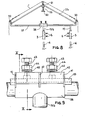
- Figures 8 to 10 show another form of embodiment of the awning, so that in this case the bearing structure (2b) is, like in the previous case, formed by a single tubular piece but in this new embodiment, the section is closed to determine a triangular outline (Figure 8) which will configure the double sloped awning.
- the cloth (1) is tightened by the tightening element - (21), and fixed by the lateral fixing elements (20); whereas the coupling and fixing of the bearing structure (2b) on the top sections (4) of the scaffolding is effected by means of the lower sections - (19) and (19b), which have their corresponding bush or sleeve (3) and the radial tightening screws (6).
- the said lower sections (19) and (19b) are arranged on the lower horizontal branch (37) of the bearing structure (2b), section (19) being fixed and section (19b) being movable and may be moved along the said bottom horizontal branch (37).
- the movable section (19b) is solid with a bush (38) which slides along the horizontal branch, in order to take apart or bring closer together the sections (19) and (19b), permitting their attache- ment to any conventional scaffolding.
- inverted U section (39) On the horizontal tubular branch (37) there is welded at the top and lengthwise an inverted U section (39) which is constituted as a runner to prevent the rotation of a section (40) in which the bush (38) extends.
- This section (40) has some lateral stiffeners (41) and is in turn provided with threaded holes (42) for respective screws (43) passing through the tightening nut (44), washer - (45) and the corresponding threaded hole or orifice (42).
Landscapes
- Engineering & Computer Science (AREA)
- Architecture (AREA)
- Mechanical Engineering (AREA)
- Civil Engineering (AREA)
- Structural Engineering (AREA)
- Building Awnings And Sunshades (AREA)
- Tents Or Canopies (AREA)
Applications Claiming Priority (6)
| Application Number | Priority Date | Filing Date | Title |
|---|---|---|---|
| ES287686U | 1985-06-26 | ||
| ES1985287686U ES287686Y (es) | 1985-06-26 | 1985-06-26 | Toldo de proteccion sobre andamiajes y estructuras tubulares |
| ES290818U | 1985-12-06 | ||
| ES1985290818U ES290818Y (es) | 1985-12-06 | 1985-12-06 | Toldo de proteccion perfeccionado, para andamiajes y estruc-turas tubulares |
| ES293106U | 1986-03-20 | ||
| ES1986293106U ES293106Y (es) | 1986-03-20 | 1986-03-20 | Toldo de proteccion perfeccionado para andamiajes utilizados en obras de construccion |
Publications (2)
| Publication Number | Publication Date |
|---|---|
| EP0207008A2 true EP0207008A2 (de) | 1986-12-30 |
| EP0207008A3 EP0207008A3 (de) | 1987-10-21 |
Family
ID=27240665
Family Applications (1)
| Application Number | Title | Priority Date | Filing Date |
|---|---|---|---|
| EP86830113A Withdrawn EP0207008A3 (de) | 1985-06-26 | 1986-05-07 | Schirmdach für Baugerüste und Rohrkonstruktionen |
Country Status (2)
| Country | Link |
|---|---|
| US (1) | US4739592A (de) |
| EP (1) | EP0207008A3 (de) |
Cited By (8)
| Publication number | Priority date | Publication date | Assignee | Title |
|---|---|---|---|---|
| EP0368393A1 (de) * | 1988-11-07 | 1990-05-16 | Rudolf Felix Maria Giling | Vorrichtung zum Abschirmen der Aussenseite eines Gebäudes |
| GB2265931B (en) * | 1992-11-17 | 1995-11-08 | Tubular Access Ltd | A canopy |
| EP0867581A1 (de) * | 1997-03-25 | 1998-09-30 | Luigi Fontana | Gerüst mit Wetterschutzvorrichtung |
| US6158181A (en) * | 1997-12-19 | 2000-12-12 | Musgrave; Paul Barnaby | Roofing structures |
| WO2011023741A1 (fr) * | 2009-08-26 | 2011-03-03 | Solvay Sa | Procédé pour fabriquer un édifice susceptible de produire de l'électricité |
| DE102010060377A1 (de) * | 2010-11-05 | 2012-05-10 | IBEK Gerüstbau GmbH | Wetterschutzvorrichtung für ein Baugerüst und Aufsatzelement für eine Wetterschutzvorrichtung |
| GB2570028A (en) * | 2017-10-27 | 2019-07-10 | Flexi Roof Coverings Ip Holding Ltd | Modular scaffold cover assembly for roof |
| CN110242060A (zh) * | 2019-05-13 | 2019-09-17 | 浙江大东吴集团建设有限公司 | 一种车间建安工程光污染防治结构 |
Families Citing this family (8)
| Publication number | Priority date | Publication date | Assignee | Title |
|---|---|---|---|---|
| DE4122088A1 (de) * | 1991-07-04 | 1993-01-07 | Ruediger Dipl Ing Behrend | Zeltbauwerk |
| US5261193A (en) * | 1992-02-26 | 1993-11-16 | Birdair, Inc. | Tensioned membrane cladding system |
| NL1011041C2 (nl) * | 1998-11-10 | 2000-05-11 | Haan Serrebouw B V De | Afschermsysteem voor het afschermen van werkzaamheden aan een gevel en bijbehorende haring. |
| US20060175131A1 (en) * | 2005-02-09 | 2006-08-10 | Smith Jeffrey M | Protective weather-frame canopy enclosure for scaffolding |
| US9447601B2 (en) | 2015-01-30 | 2016-09-20 | Jack J. Maillis | Portable environmental containment unit |
| CN104806041B (zh) * | 2015-05-25 | 2017-03-08 | 陈科 | 为旅游者上厕所提供方便的应急装置 |
| WO2016201542A1 (en) * | 2015-06-17 | 2016-12-22 | Srs Scaffolding Solutions Inc. | Enclosure system for scaffolding |
| EP3323731B1 (de) * | 2016-11-17 | 2020-04-22 | Airbus Operations S.L. | Aufzugssystem für eine hilfsstromeinheit |
Family Cites Families (17)
| Publication number | Priority date | Publication date | Assignee | Title |
|---|---|---|---|---|
| US576858A (en) * | 1897-02-09 | knopfe | ||
| US2144747A (en) * | 1937-07-16 | 1939-01-24 | John Q Adams | Collapsible tent |
| GB589443A (en) * | 1944-11-07 | 1947-06-20 | Bryant & Son Ltd C | Improvements relating to scaffolding |
| US2787321A (en) * | 1955-12-12 | 1957-04-02 | James E Dietz | Head rod holder |
| DE1751026U (de) * | 1957-05-03 | 1957-08-22 | Theodor Terlinden | Zusammensetzbares gewaechshaus mit einem lichtdurchlaessigen relag aus kunststoff-folie. |
| GB947361A (en) * | 1961-03-08 | 1964-01-22 | Andrew Phillips | Roof structure |
| US3121470A (en) * | 1962-05-11 | 1964-02-18 | Allen W Stone | Protective covering for scaffolding |
| CA852526A (en) * | 1968-03-14 | 1970-09-29 | Mollinger Sebastian | Connection of sheets to cables or rods |
| US3844080A (en) * | 1971-09-08 | 1974-10-29 | Ici Ltd | Suspended ceiling |
| BE781945A (fr) * | 1972-04-12 | 1972-07-31 | Jambes Namur Anciens Ets Theop | Dispositif favorisant la finition en plein air de reservoirs degrandes dimensions, generalement d'allure spherique |
| DE2500285A1 (de) * | 1975-01-04 | 1976-07-08 | Fritz Bruecher | Bauelement zum tragen und spannen einer dachhaut |
| DE2637298A1 (de) * | 1976-08-19 | 1978-02-23 | Rupert Sonnauer | Wetterschutzvorrichtung fuer ein zerlegbares geruest |
| DE2649395A1 (de) * | 1976-10-29 | 1978-05-11 | Hoecker Stahlbau Kg Karl | Aus einem demontierbaren traggeruest bestehendes zelt |
| AU516446B2 (en) * | 1977-12-13 | 1981-06-04 | Haya Pty. Ltd. | Annexe |
| DE3244905A1 (de) * | 1981-12-10 | 1983-07-21 | Müller & Baum GmbH & Co KG, 5768 Sundern | Tragkonstruktion fuer eine wetterverkleidung an einem baugeruest |
| FR2523622A1 (fr) * | 1982-03-18 | 1983-09-23 | Perradin Guy | Procede pour la realisation de faux-plafonds et faux-plafonds obtenus |
| GB2145761A (en) * | 1983-08-04 | 1985-04-03 | Midlands Environmental Service | Roof structure and bracket for use in supporting said structure |
-
1986
- 1986-05-07 EP EP86830113A patent/EP0207008A3/de not_active Withdrawn
- 1986-06-24 US US06/878,054 patent/US4739592A/en not_active Expired - Fee Related
Cited By (8)
| Publication number | Priority date | Publication date | Assignee | Title |
|---|---|---|---|---|
| EP0368393A1 (de) * | 1988-11-07 | 1990-05-16 | Rudolf Felix Maria Giling | Vorrichtung zum Abschirmen der Aussenseite eines Gebäudes |
| GB2265931B (en) * | 1992-11-17 | 1995-11-08 | Tubular Access Ltd | A canopy |
| EP0867581A1 (de) * | 1997-03-25 | 1998-09-30 | Luigi Fontana | Gerüst mit Wetterschutzvorrichtung |
| US6158181A (en) * | 1997-12-19 | 2000-12-12 | Musgrave; Paul Barnaby | Roofing structures |
| WO2011023741A1 (fr) * | 2009-08-26 | 2011-03-03 | Solvay Sa | Procédé pour fabriquer un édifice susceptible de produire de l'électricité |
| DE102010060377A1 (de) * | 2010-11-05 | 2012-05-10 | IBEK Gerüstbau GmbH | Wetterschutzvorrichtung für ein Baugerüst und Aufsatzelement für eine Wetterschutzvorrichtung |
| GB2570028A (en) * | 2017-10-27 | 2019-07-10 | Flexi Roof Coverings Ip Holding Ltd | Modular scaffold cover assembly for roof |
| CN110242060A (zh) * | 2019-05-13 | 2019-09-17 | 浙江大东吴集团建设有限公司 | 一种车间建安工程光污染防治结构 |
Also Published As
| Publication number | Publication date |
|---|---|
| EP0207008A3 (de) | 1987-10-21 |
| US4739592A (en) | 1988-04-26 |
Similar Documents
| Publication | Publication Date | Title |
|---|---|---|
| EP0207008A2 (de) | Schirmdach für Baugerüste und Rohrkonstruktionen | |
| DE10047400C2 (de) | Photovoltaische Solarvorrichtung | |
| DE4308745C2 (de) | Ebener oder räumlicher Deckenrost aus Stäben und Knotenstücken, insbesondere begehbarer Deckenrost | |
| CH693535A5 (de) | Faltbares Dach und Stellwand als Wind- und Wetterschutz, sowie Pavillon mit einem Dach und einer Stellwand. | |
| WO1996018857A2 (de) | Universal-stapel-, -transport- und -montageelement für solarenergieaufnahme, -speicherung usf. sowie deren befestigung | |
| DE4209810A1 (de) | Werbeaufsteller | |
| DE102005053639B4 (de) | Befestigungssystem für Solarmodule | |
| DE102008008923B4 (de) | Leicht handhabbares Gestell für Dachaufbauten an Flachdächern und geneigten Flachdächern | |
| JPS6322282Y2 (de) | ||
| EP1321600B1 (de) | Regenmarkise | |
| DE19915621A1 (de) | Schutzzelt für Dacharbeiten | |
| DE20106237U1 (de) | Schutzdach | |
| JP3709173B2 (ja) | 屋根上工事用日よけ装置 | |
| EP1426527A1 (de) | Montageeinrichtung für einen Tragteil und Absturzsicherung mit einer solchen Montageeinrichtung | |
| EP1808551A2 (de) | Dach mit Zubehörhalterung | |
| DE3520358A1 (de) | Pultdach, insbesondere fuer einen vorzugsweise vor eine gebaeudewand setzbaren wintergarten, mit aus profilen gefertigten dachstreben | |
| JP4203491B2 (ja) | 庇 | |
| GB2093144A (en) | Improvements in greenhouse frames | |
| JPH0725150U (ja) | 建築工事用仮設屋根 | |
| DE202004010814U1 (de) | Solareinheit für Photovoltaik-Energieanlagen und andere Solar-Energieanlagen | |
| KR200307395Y1 (ko) | 에어컨 실외기용 받침대 | |
| DE3418994A1 (de) | Zeltkonstruktion | |
| JP2781319B2 (ja) | 手摺りの取付け方法 | |
| AU2002301841B2 (en) | A Method of Construction | |
| JPH0718804A (ja) | 庇ユニット及びこの庇ユニットを用いた庇 |
Legal Events
| Date | Code | Title | Description |
|---|---|---|---|
| PUAI | Public reference made under article 153(3) epc to a published international application that has entered the european phase |
Free format text: ORIGINAL CODE: 0009012 |
|
| AK | Designated contracting states |
Kind code of ref document: A2 Designated state(s): AT BE CH DE FR GB IT LI LU NL SE |
|
| PUAL | Search report despatched |
Free format text: ORIGINAL CODE: 0009013 |
|
| AK | Designated contracting states |
Kind code of ref document: A3 Designated state(s): AT BE CH DE FR GB IT LI LU NL SE |
|
| 17P | Request for examination filed |
Effective date: 19880415 |
|
| 17Q | First examination report despatched |
Effective date: 19890713 |
|
| STAA | Information on the status of an ep patent application or granted ep patent |
Free format text: STATUS: THE APPLICATION IS DEEMED TO BE WITHDRAWN |
|
| 18D | Application deemed to be withdrawn |
Effective date: 19900124 |