EP0207015A2 - Belüfteter Kollektor für ein Gasverteilungsnetz für Haushalt- oder andere Benutzer - Google Patents
Belüfteter Kollektor für ein Gasverteilungsnetz für Haushalt- oder andere Benutzer Download PDFInfo
- Publication number
- EP0207015A2 EP0207015A2 EP86830170A EP86830170A EP0207015A2 EP 0207015 A2 EP0207015 A2 EP 0207015A2 EP 86830170 A EP86830170 A EP 86830170A EP 86830170 A EP86830170 A EP 86830170A EP 0207015 A2 EP0207015 A2 EP 0207015A2
- Authority
- EP
- European Patent Office
- Prior art keywords
- pipe
- ventilated
- sheath
- gas
- manifold
- Prior art date
- Legal status (The legal status is an assumption and is not a legal conclusion. Google has not performed a legal analysis and makes no representation as to the accuracy of the status listed.)
- Withdrawn
Links
Images

Classifications
-
- F—MECHANICAL ENGINEERING; LIGHTING; HEATING; WEAPONS; BLASTING
- F16—ENGINEERING ELEMENTS AND UNITS; GENERAL MEASURES FOR PRODUCING AND MAINTAINING EFFECTIVE FUNCTIONING OF MACHINES OR INSTALLATIONS; THERMAL INSULATION IN GENERAL
- F16L—PIPES; JOINTS OR FITTINGS FOR PIPES; SUPPORTS FOR PIPES, CABLES OR PROTECTIVE TUBING; MEANS FOR THERMAL INSULATION IN GENERAL
- F16L9/00—Rigid pipes
- F16L9/18—Double-walled pipes; Multi-channel pipes or pipe assemblies
-
- F—MECHANICAL ENGINEERING; LIGHTING; HEATING; WEAPONS; BLASTING
- F16—ENGINEERING ELEMENTS AND UNITS; GENERAL MEASURES FOR PRODUCING AND MAINTAINING EFFECTIVE FUNCTIONING OF MACHINES OR INSTALLATIONS; THERMAL INSULATION IN GENERAL
- F16L—PIPES; JOINTS OR FITTINGS FOR PIPES; SUPPORTS FOR PIPES, CABLES OR PROTECTIVE TUBING; MEANS FOR THERMAL INSULATION IN GENERAL
- F16L39/00—Joints or fittings for double-walled or multi-channel pipes or pipe assemblies
- F16L39/005—Joints or fittings for double-walled or multi-channel pipes or pipe assemblies for concentric pipes
-
- F—MECHANICAL ENGINEERING; LIGHTING; HEATING; WEAPONS; BLASTING
- F17—STORING OR DISTRIBUTING GASES OR LIQUIDS
- F17D—PIPE-LINE SYSTEMS; PIPE-LINES
- F17D1/00—Pipe-line systems
- F17D1/02—Pipe-line systems for gases or vapours
- F17D1/04—Pipe-line systems for gases or vapours for distribution of gas
-
- F—MECHANICAL ENGINEERING; LIGHTING; HEATING; WEAPONS; BLASTING
- F17—STORING OR DISTRIBUTING GASES OR LIQUIDS
- F17D—PIPE-LINE SYSTEMS; PIPE-LINES
- F17D5/00—Protection or supervision of installations
- F17D5/02—Preventing, monitoring, or locating loss
- F17D5/04—Preventing, monitoring, or locating loss by means of a signalling fluid enclosed in a double wall
Definitions
- the present invention relates to gas supply lines under pressure - even very limited - for the distribution of combustible gas to domestic installations or other types, and relates more particularly to a ventilated gas distribution manifold for domestic use or other.
- the main object of the present invention is to provide a ventilated gas distribution manifold for domestic and other use which eliminates the drawbacks of the distribution networks known to date, and in particular adapted to prevent gas leaks to the local by channeling possible leaks to an exhaust system in a safe place, i.e. outside.
- a ventilated gas distribution manifold for household or other use, characterized in that it comprises a gas transport pipe, a sealed ventilation duct, surrounding, coaxial and connected to said pipe so as to delimit several interstices at atmospheric pressure for the collection and flow of any gas leaks which come from the pipe, through discharges in communication with the outside.
- a tubular sheath For the continuous sections of pipe, a tubular sheath is provided, the connection of which to the internal pipe is obtained either by deformations located inwards or by means of a series of spaced apart radial walls disposed between said sheath and said pipe and intended to delimit communicating longitudinal chambers for collecting and flowing gas, said walls extending radially from said external sheath, in one piece with it, towards said internal pipe.
- screw and sliding sleeve couplings are provided, placed on the tubular sheaths and capable of forming a seal on the sheaths by the presence of annular ranges received in parts with internal channel and deformable to obtain a reduction in diameter of said sleeves.
- elbows and branches can be formed around such bends and such branches, geometrically similar corresponding structures, which form passage interstices according to the conformation of the elbows and branches, to ensure the continuity of the interstices or collection chambers and flow formed by the sheaths around the pipes, or as a variant, elbows and branches can be provided integral with parts forming annular sheaths in the connection zones of these parts, to obtain the possibility of connection with contiguous sections of manifold; in correspondence of curves and connections. bypass. The section being reduced compared to the annular section which they form concentrically with the fittings, but always ensuring the continuity of the interstice or of the collection and flow chambers.
- the fittings in particular the sleeve seals, single and multiple fittings, comprise at least one tubular body intended to engage with one of its ends the sheathed internal pipe, an annular chamber , in correspondence of said end, delimited by the external surface of said pipe. Said chamber being in communication with said interstices or said chambers; means for communicating said chamber with said discharge conduits; means for sealingly blocking said internal pipe in said tubular body.
- said tubular body internally delimits a duct having at least first and second ends, and which has an intermediate section of frustoconical shape flared towards said second end; said means for hermetically blocking said internal pipe in said tubular body pipe whose end is widened and made to correspond to said frustoconical section.
- a frustoconical element intended to cause the watertight forcing of this widened end against said frustoconical section, said frustoconical element being blocked by a locking nut;
- said tubular body is formed of an internal metallic element and an external tubular plastic element, the latter being intended for assembly by electrical welding, by means of an auxiliary sleeve. external gain, plastic.
- the internal pipe of the collector can be made of copper or aluminum and the external sheath of aluminum or of self-extinguishing plastic material, or else the internal pipe and the external sheath can both be made of aluminum with plastic film coating, or finally the internal pipe and the external sheath which make up the collector can both be made of self-extinguishing plastic.
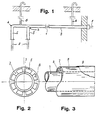
- a ventilated manifold for the distribution of gas in accordance with the invention comprises a pipe 1 for transporting the gas, any branching 2 thereof and the sleeves, fittings 3 and the elbows 4, ducts of ventilation 5 surrounding coaxial and stably connected to said pipe so as to delimit protective gaps to prevent the dispersion of gas as a result of possible leaks which may occur in the gas distribution pipe.
- the gap formed by the sheath 5 is at atmospheric pressure, being placed in communication with one or more evacuation tubes 6 which open to the outside and in a position such as to present no danger in the event of gas losses.
- FIGS 2 and 3 which respectively show a cross section and a partial longitudinal view of a first embodiment of the ventilated manifold according to the invention
- a manifold composed of a pipe 1 for the trans gas port and an external ventilation duct 5 coaxial to the first and of larger diameter, usable for a continuous section of the network.
- the sheath 5 is provided with a series of walls 7 also spaced apart and extending axially.
- the length of the walls 7 is such that it allows precise coupling between the pipe 1 and the sheath 5 and the corresponding centering.
- the walls 7 extend radially from the sheath 5 towards the center, forming a single body.
- the walls 7 delimit, in the space between the pipe 1 and the sheath 5. as many chambers 8 in which is collected the gas coming from possible leaks from the pipe 1. To put the various chambers 8 in communication with each other along the sheath, the walls 7 are advantageously provided with appropriate communication openings. All the chambers 8 converge in a discharge tube (like those indicated in 6 in FIG. 1).
- the gas transport pipe and the external sheath 5 can be made either of aluminum or of plastic.
- the pipe 1 is made of copper or aluminum while the sheath is preferably made of aluminum or plastic.
- the outer sheath if it is made of aluminum, must be coated with a thin film 9 of polyethylene or other self-extinguishing material, possibly colored, for a protective purpose.
- a collector of this kind can be produced in very long pieces (eg 50 m) to be wound up in rolls and with a sheath diameter of more than 25 mm.
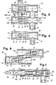
- the connections for the ventilated collector according to FIG. 2 and 3 comprise a single connector, a multiple connector and a sleeve joint with a metal body, illustrated respectively in FIGS. 4, 5 and 6.
- the simple connector 10 of FIG. 4 which adapts for example the manifold of FIG. 2 and 3 to a service terminal comprises a tubular body which delimits an internal conduit 12 situated between a first end 11 a, a service end 11 b and a second end 13 placed at 90 ° relative to the axis of the conduit 12
- the internal conduit 12 has a frustoconical section 18 with flaring oriented towards the service end 11b.
- a peripheral seat 9 for another sealing ring is provided.
- the double connector 20 of FIG. 5 is obtained simply by putting the second end of a first simple connector 10 into communication with the internal conduit 12 'of a similar second connector 10'.
- the connection 13 is aligned with the second end 13 'of the tubular body 11'.
- the two evacuation connections 17 and 17 ′ open into a common sub-collector 21 intended to be connected to the discharge pipe, not shown.
- This double connection 20 can for example be. used when you want to create a branch on a gas distribution network.
- connection joint illustrated in FIG. 6 for two sections of the manifold illustrated in FIGS. 2 and 3, is formed by two tubular bodies 11 with parallel axes and forming a single body, in which the respective internal conduits 12 are placed in communication with one another by means of a passage 23 of appropriate section near the service ends 11b respectively.
- the gas loss collection chambers of the two straight sections not shown are placed in communication with one another through the chambers 15 of two tubular bodies 11 and a corresponding connection conduit 24.
- FIG. 7 is illustrated. partially in section view, the connection mode of a section 28 of the manifold illustrated in FIGS. 2 and 3, to the simple connector 10 of FIG. 4.
- This section consists of an external ventilation duct 30 made of aluminum coated with a polyethylene film 31, and is tightly connected to the connector 10.
- One end of the section 28 is inserted into the duct 12 on the side of the first end 11a, after fitting a sealing ring 32 in the seat 14, so that the end of the external sheath 30, 31 comes to bear on the stop 16 of the chamber 15 and that the pipe internal 29 extends to the frusto-conical section 18.
- the end of the pipe 29 is widened with a suitable tool so as to make it correspond with the frusto-conical section 18 after fitting a sealing ring 33 in the seat 19.
- a tubular frustoconical element 34 is thus applied in the enlarged end 29a of the internal pipe, which is then blocked with a nut 35, both being introduced by the service end 11 which is finally closed with a plug. 36.
- Chamber 15 hermetically sealed by means of sealing rings 32 and 33 collect any losses of gas flowing in the chambers of the ventilated manifold and evacuate them in turn to a discharge conduit through the connection 17.
- FIG. 8 9 and 10 are illustrated in section, respectively a sleeve 37, a multiple connector 38 and a single connector 39 adapted for a collector with an external plastic sheath, the body of the machon or of the fitting being made of similar plastic material.
- the tubular body 11 consists of an internal metallic tubular element 11d which internally delimits the conduit 12 with a frustoconical section 18, and an external tubular element 11c of plastic which completely covers it and extends up to the first end 11 a of the body 11.
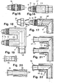
- the connection between the sleeves 37, the fittings 38 and 39 and the ventilated manifold with external plastic sheath is carried out according to traditional techniques by means of auxiliary connection sleeves 40, 41 and 42, which are illustrated in FIG.
- the sleeve 40 shown in side view in FIG. 11 and front on FIG. 12 can be used to assemble the double connector 38 of FIG. 9 with two sections of ventilated collector. In this case the connection of the discharges, indicated at 45, is provided on the auxiliary sleeve itself.
- the auxiliary sleeve 41 of FIG. 13 can be used in combination with the connector 37 of FIG. 8 while the auxiliary connector 42 of FIG. 14 can be used in combination with the single fitting 39 illustrated in FIG. 10.
- FIG. 15 is illustrated a connector 46 which can be used for the axial connection of sections of ventilated manifold with an external plastic sheath, and intended to be then covered with the sleeve 41 of FIG. 13, which is thus electro-welded to the two sections.
- FIGs. 16, 17 and 18 Other alternative embodiments of the connections of the ventilated manifold according to the present invention, based on the principle of the connection 46 of FIG 15, are shown in FIGs. 16, 17 and 18.
- the first end 11a of the tubular body 11 of the fittings 47, 48 and 49 has a threaded section 50 and a frustoconical section 51 with an intermediate peripheral groove 52.
- the enlarged end of the internal pipe 29 of the section 28 of the manifold is applied to the frustoconical section 51, on which a frustoconical stiffening collar 53 is placed and finally the whole is blocked with a nut 54 (FIG. 17).
- FIG. 19 illustrates another type of connector 55 which can be used to axially connect two sections of ventilated manifold by electrically welding by means of an auxiliary tool chosen from those illustrated in FIGS. 11 to 14, placed on the aforementioned seal 55.
- the internal pipe of the ventilated manifold is then simply engaged in the gasket 55, the seal being ensured by a suitable packing, not shown.
- FIG. 20 21 and 22 is illustrated the practical application of the seal 55 of FIG. 19 to the connections to be used with the ventilated manifold shown in FIGS. 2 and 3 of the accompanying drawings.
- the body 11 of these connections 56, 57 and 58 has an internal tubular element 11 d of metal and an external tubular element 11 c of plastic coating.
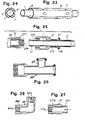
- FIG. 23 and 24 which respectively show in perspective and in section a second embodiment of the ventilated gas distribution manifold of FIG. 1, the pipe for gas 1 made of copper or aluminum is surrounded by a sheath 5 'also made of copper or aluminum, which has localized internal projections 7' intended to ensure the centering of the sheath on the internal pipe, and therefore form the communicating interstices 8 '
- FIG. 25 a piece of pipe 1 and a connector 60 threaded at their ends at 1a and 60a, are directly coupled together to form the gas transport pipe.
- the piece of pipe 1 is surrounded by the sheath 5 'with a connector 61 threaded at 61a, while the connector 60 is surrounded by a sleeve connector 62 with thread at 62a.
- the mancon 61 can be assembled on one side with its thread 61 a to the thread 62a of the connector 62.
- FIG. 26 is shown a sleeve 65 similar to the sleeve 61, but provided with a deformable and profiled branch 66 like the part 63 of the sleeve 61, so as to be clamped on a branch discharge pipe such as that indicated in 6.
- FIGS. 27 and 28 show two rectilinear end terminals 67 and elbow 68. These have threads 67a and 68a for connection with the gas pipe of the ventilated manifold, and threads 67c and 68c for connection with the sheath of the ventilated manifold.
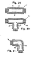
- FIG. 29 shows a ventilated sleeve fitting 69 with two parts 70 and 71 coaxial and provided with end threads for the continuity of the pipe and the collector sheath.
- these parts 70 and 71 have the coupling function between the adjacent pipes, and form a ventilation passage 72 between them.
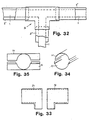
- FIG. 30 and 31 is illustrated an exemplary embodiment of the intersector in a T 73 and elbow 74 branch, similar sheaths 75 in T and elbow 76 being produced outside the parts 73 and 74 by means of appropriate methods. known per se.
- the connections 75 and 76 form ventilation passages 77 and 78 around the connections 73 and 74, and are provided at their ends with threads (like the parts 73 and 74) to engage contiguous elements for the formation of the ventilation gap 8 'around the contiguous sections of pipe to be protected.
- connections described with reference to FIG. 25 to 31 are made of copper or aluminum.
- the 5 "sheath and the connections of the ventilated manifold illustrated in FIG. 32 are made of metal or plastic, electrically welded on site.
Landscapes
- Engineering & Computer Science (AREA)
- General Engineering & Computer Science (AREA)
- Mechanical Engineering (AREA)
- Pipeline Systems (AREA)
- Rigid Pipes And Flexible Pipes (AREA)
Applications Claiming Priority (6)
| Application Number | Priority Date | Filing Date | Title |
|---|---|---|---|
| IT1168585U | 1985-06-18 | ||
| IT1168585U IT8511685V0 (it) | 1985-06-18 | 1985-06-18 | Raccorderia, in particolare giunti, manicotti, raccordi singoli e multipli, per collettori ventilati |
| IT1168685U IT209119Z2 (it) | 1985-06-18 | 1985-06-18 | Collettore ventilato per reti di distribuzione gas |
| IT1168685U | 1985-06-18 | ||
| IT952585 | 1985-11-25 | ||
| IT09525/85A IT1201384B (it) | 1985-11-25 | 1985-11-25 | Complesso di raccordi e guaine per scopi antideflagranti e di protezione contro perdite dalle condutture di gas in installazioni domestiche ed altro |
Publications (2)
| Publication Number | Publication Date |
|---|---|
| EP0207015A2 true EP0207015A2 (de) | 1986-12-30 |
| EP0207015A3 EP0207015A3 (de) | 1990-05-02 |
Family
ID=27272744
Family Applications (1)
| Application Number | Title | Priority Date | Filing Date |
|---|---|---|---|
| EP86830170A Withdrawn EP0207015A3 (de) | 1985-06-18 | 1986-06-18 | Belüfteter Kollektor für ein Gasverteilungsnetz für Haushalt- oder andere Benutzer |
Country Status (1)
| Country | Link |
|---|---|
| EP (1) | EP0207015A3 (de) |
Cited By (18)
| Publication number | Priority date | Publication date | Assignee | Title |
|---|---|---|---|---|
| FR2697892A1 (fr) * | 1992-11-10 | 1994-05-13 | Nobel Plastiques | Canalisation de carburant, notamment pour raccorder le réservoir de carburant d'un véhicule au moteur dudit véhicule. |
| EP0592639A4 (en) * | 1992-03-27 | 1994-07-27 | Advanced Polymer Technology | Secondary containment flexible underground piping system |
| WO1996007089A1 (de) * | 1994-08-27 | 1996-03-07 | Bernd Brandes | Verfahren zur überwachung der dichtheit von rohrleitungen, insbesondere abwasserleitungssystemen, und eine vorrichtung zur durchführung des verfahrens |
| US5527130A (en) * | 1992-02-19 | 1996-06-18 | Environ Products, Inc. | Environmentally safe underground piping system |
| EP0727023A4 (de) * | 1993-11-01 | 1997-01-02 | Andrew Youngs | Sekundäres rückhaltesystem unter verwendung flexibler untergrundrohre |
| WO1997012165A1 (de) * | 1995-09-28 | 1997-04-03 | Siemens Aktiengesellschaft | Fluidleitung mit integriertem drucklosen rücklauf |
| US5775842A (en) * | 1988-12-20 | 1998-07-07 | Pisces By Opw, Inc. | Double containment under ground piping system |
| WO1998035178A1 (de) * | 1997-02-11 | 1998-08-13 | Kroener Josef | Doppelrohrsystem, verfahren und werkzeuge zu dessen herstellung |
| US5911155A (en) * | 1992-08-03 | 1999-06-08 | Environ Products, Inc. | Connecting device for pipe assemblies |
| US6032699A (en) * | 1997-05-19 | 2000-03-07 | Furon Company | Fluid delivery pipe with leak detection |
| WO2000071925A1 (de) * | 1999-05-19 | 2000-11-30 | Balogh Jeno | Rohrleitungssystem zur weiterleitung von wärmeträgermitteln |
| EP1424521A1 (de) * | 2002-11-28 | 2004-06-02 | Audi Ag | Rohrförmiges Fluidführungsteil |
| GB2425812A (en) * | 2005-04-20 | 2006-11-08 | Anton Paar Gmbh | Vented two layer pipe |
| EP2372222A1 (de) * | 2010-03-29 | 2011-10-05 | MT-Energie GmbH | Vorrichtung zum Führen von im Betrieb von Biogasanlagen, Kläranlagen oder landwirtschaftlichen Anlagen anfallenden Fluiden |
| EP3239564A1 (de) * | 2016-04-29 | 2017-11-01 | Airbus Operations GmbH | Ummantelte ventilanordnung |
| EP2653765B1 (de) * | 2012-04-20 | 2019-02-27 | TI Automotive (Heidelberg) GmbH | Rohrleitung für ein zu temperierendes fluides Medium |
| CN110118309A (zh) * | 2019-06-13 | 2019-08-13 | 新天绿色能源股份有限公司 | 一种管道监测装置 |
| US10969028B2 (en) | 2016-04-29 | 2021-04-06 | Airbus Operations Gmbh | Shrouded valve assembly |
Families Citing this family (1)
| Publication number | Priority date | Publication date | Assignee | Title |
|---|---|---|---|---|
| US5865216A (en) | 1995-11-08 | 1999-02-02 | Advanced Polymer Technology, Inc. | System for housing secondarily contained flexible piping |
Family Cites Families (8)
| Publication number | Priority date | Publication date | Assignee | Title |
|---|---|---|---|---|
| US1435555A (en) * | 1918-10-16 | 1922-11-14 | Air Reduction | Method of distributing gases |
| CH391407A (de) * | 1962-04-03 | 1965-04-30 | Wepf Robert | Pipe-Line, Verfahren zur Herstellung derselben sowie Anlage zur Durchführung dieses Verfahrens |
| CH382506A (de) * | 1962-09-13 | 1964-09-30 | Beuglet Andre | Behälter mit Wandbelag zu Kontrollzwecken |
| DE1475842A1 (de) * | 1965-11-02 | 1969-03-13 | Siemens Ag | Einrichtung zur Leckueberwachung von Rohrleitungen |
| DE2202826A1 (de) * | 1971-02-23 | 1972-08-31 | British Petroleum Co | Rohrleitung |
| CH567226A5 (en) * | 1972-11-01 | 1975-09-30 | Scheuchzer Auguste Les Fils De | Underwater gas pipe leakage protection system - comprises liquid-filled enclosing sheath leading gas clear of water |
| CH580781A5 (en) * | 1973-05-07 | 1976-10-15 | Scheuchzer Auguste Les Fils De | Anti-pollution pipeline section - has meshwork packings between tube and longitudinally split shorter casing forming stepped ends |
| US4157194A (en) * | 1976-05-27 | 1979-06-05 | Tokan Kogyo Co., Ltd. | Thermoplastic multi-walled pipes |
-
1986
- 1986-06-18 EP EP86830170A patent/EP0207015A3/de not_active Withdrawn
Cited By (20)
| Publication number | Priority date | Publication date | Assignee | Title |
|---|---|---|---|---|
| US5775842A (en) * | 1988-12-20 | 1998-07-07 | Pisces By Opw, Inc. | Double containment under ground piping system |
| US6116817A (en) * | 1988-12-20 | 2000-09-12 | Pisces By Opw, Inc. | Hydrocarbon fuel piping system with a flexible inner pipe and an outer pipe |
| US5527130A (en) * | 1992-02-19 | 1996-06-18 | Environ Products, Inc. | Environmentally safe underground piping system |
| EP0592639A4 (en) * | 1992-03-27 | 1994-07-27 | Advanced Polymer Technology | Secondary containment flexible underground piping system |
| US5911155A (en) * | 1992-08-03 | 1999-06-08 | Environ Products, Inc. | Connecting device for pipe assemblies |
| FR2697892A1 (fr) * | 1992-11-10 | 1994-05-13 | Nobel Plastiques | Canalisation de carburant, notamment pour raccorder le réservoir de carburant d'un véhicule au moteur dudit véhicule. |
| EP0727023A4 (de) * | 1993-11-01 | 1997-01-02 | Andrew Youngs | Sekundäres rückhaltesystem unter verwendung flexibler untergrundrohre |
| WO1996007089A1 (de) * | 1994-08-27 | 1996-03-07 | Bernd Brandes | Verfahren zur überwachung der dichtheit von rohrleitungen, insbesondere abwasserleitungssystemen, und eine vorrichtung zur durchführung des verfahrens |
| WO1997012165A1 (de) * | 1995-09-28 | 1997-04-03 | Siemens Aktiengesellschaft | Fluidleitung mit integriertem drucklosen rücklauf |
| WO1998035178A1 (de) * | 1997-02-11 | 1998-08-13 | Kroener Josef | Doppelrohrsystem, verfahren und werkzeuge zu dessen herstellung |
| US6032699A (en) * | 1997-05-19 | 2000-03-07 | Furon Company | Fluid delivery pipe with leak detection |
| WO2000071925A1 (de) * | 1999-05-19 | 2000-11-30 | Balogh Jeno | Rohrleitungssystem zur weiterleitung von wärmeträgermitteln |
| EP1424521A1 (de) * | 2002-11-28 | 2004-06-02 | Audi Ag | Rohrförmiges Fluidführungsteil |
| GB2425812A (en) * | 2005-04-20 | 2006-11-08 | Anton Paar Gmbh | Vented two layer pipe |
| EP2372222A1 (de) * | 2010-03-29 | 2011-10-05 | MT-Energie GmbH | Vorrichtung zum Führen von im Betrieb von Biogasanlagen, Kläranlagen oder landwirtschaftlichen Anlagen anfallenden Fluiden |
| EP2653765B1 (de) * | 2012-04-20 | 2019-02-27 | TI Automotive (Heidelberg) GmbH | Rohrleitung für ein zu temperierendes fluides Medium |
| EP3239564A1 (de) * | 2016-04-29 | 2017-11-01 | Airbus Operations GmbH | Ummantelte ventilanordnung |
| US10844971B2 (en) | 2016-04-29 | 2020-11-24 | Airbus Operations Gmbh | Shrouded valve assembly |
| US10969028B2 (en) | 2016-04-29 | 2021-04-06 | Airbus Operations Gmbh | Shrouded valve assembly |
| CN110118309A (zh) * | 2019-06-13 | 2019-08-13 | 新天绿色能源股份有限公司 | 一种管道监测装置 |
Also Published As
| Publication number | Publication date |
|---|---|
| EP0207015A3 (de) | 1990-05-02 |
Similar Documents
| Publication | Publication Date | Title |
|---|---|---|
| EP0207015A2 (de) | Belüfteter Kollektor für ein Gasverteilungsnetz für Haushalt- oder andere Benutzer | |
| CA3154857C (fr) | Dispositif d'echappement anti propagation de batteries lithium-ion d'aeronef | |
| FR3040727A1 (fr) | Procede de fabrication d'un troncon double enveloppe | |
| EP0965784A1 (de) | Schutzhülle für Kabel oder Rohrleitungen | |
| EP3167322A1 (de) | Endkupplung für eine faseroptische schaltung, verfahren zum anschluss solch einer schaltung an eine derartige kupplung und entsprechendes dichtelement | |
| EP1248029B1 (de) | Schnellkupplung für die lösbare Verbindung zweier Rohrleitungen und ihre Verwendung | |
| FR2475306A1 (fr) | Boite de jonction universelle pour cables de telecommunications ou de puissance | |
| FR2863032A1 (fr) | Raccord a sertir pour tubes multicouches | |
| EP1547728B1 (de) | Backe für Pressverbindung | |
| FR2562198A1 (fr) | Systeme d'etancheite perfectionne, convenant particulierement pour les joints a rotule des installations immergees a grande profondeur | |
| EP1090245B1 (de) | Anordnungsverfahren zum verbinden einer armatur mit einem rohrelement und ein neuer typ kupplung zur duerchführung des verfahrens | |
| EP0160030B1 (de) | Druckmittelbetätigtes membranventil | |
| EP1571383B1 (de) | Pressfitting mit einem schneidbaren Prüfring | |
| EP1486713A1 (de) | Verpressbare Steckverbindung mit einer Nut variabler Tiefe | |
| EP1533555A1 (de) | Pressverbindung für elektrisch leitenden Rohre | |
| FR2759762A1 (fr) | Raccord isolant dielectrique et procede d'assemblage d'un tel raccord | |
| EP3204679B1 (de) | Kupplung zur kräuselung auf mindestens ein rohr, rohrsatz mit solch einer kupplung und verfahren zur montage eines rohres mit solch einer kupplung | |
| EP0148813A2 (de) | Dichtung | |
| FR3074875A1 (fr) | Dispositif de raccordement fluidique d'echangeurs thermiques d'au moins deux panneaux solaires hybrides | |
| EP1936764B1 (de) | Vorrichtung zur Verbindung von zwei Schienensystemen | |
| EP2497976B1 (de) | Dichtungsfuge | |
| EP1101055B1 (de) | Vorrichtung zum stossverbinden von rohren | |
| FR3058496B1 (fr) | Corps de jonction, raccord, systeme hydraulique pour le passage d'un fluide entre deux circuits hydrauliques, procede de montage associe | |
| EP0273819B1 (de) | Elektrolysezelle mit Leitungssystemen, die eine Kompensierung verschiedener Dehnungen enthalten | |
| EP2237385B1 (de) | Kabeldurchführungsgarnitur |
Legal Events
| Date | Code | Title | Description |
|---|---|---|---|
| PUAI | Public reference made under article 153(3) epc to a published international application that has entered the european phase |
Free format text: ORIGINAL CODE: 0009012 |
|
| AK | Designated contracting states |
Kind code of ref document: A2 Designated state(s): AT BE CH DE FR GB LI LU NL SE |
|
| PUAL | Search report despatched |
Free format text: ORIGINAL CODE: 0009013 |
|
| AK | Designated contracting states |
Kind code of ref document: A3 Designated state(s): AT BE CH DE FR GB LI LU NL SE |
|
| STAA | Information on the status of an ep patent application or granted ep patent |
Free format text: STATUS: THE APPLICATION IS DEEMED TO BE WITHDRAWN |
|
| 18D | Application deemed to be withdrawn |
Effective date: 19901103 |
|
| RIN1 | Information on inventor provided before grant (corrected) |
Inventor name: PACETTI, ANDREA |