EP0207166A1 - Verfahren und vorrichtung zur regelung eines servomotors - Google Patents
Verfahren und vorrichtung zur regelung eines servomotors Download PDFInfo
- Publication number
- EP0207166A1 EP0207166A1 EP86900261A EP86900261A EP0207166A1 EP 0207166 A1 EP0207166 A1 EP 0207166A1 EP 86900261 A EP86900261 A EP 86900261A EP 86900261 A EP86900261 A EP 86900261A EP 0207166 A1 EP0207166 A1 EP 0207166A1
- Authority
- EP
- European Patent Office
- Prior art keywords
- integral
- controller
- proportional
- motor
- command
- Prior art date
- Legal status (The legal status is an assumption and is not a legal conclusion. Google has not performed a legal analysis and makes no representation as to the accuracy of the status listed.)
- Withdrawn
Links
Images


Classifications
-
- G—PHYSICS
- G05—CONTROLLING; REGULATING
- G05B—CONTROL OR REGULATING SYSTEMS IN GENERAL; FUNCTIONAL ELEMENTS OF SUCH SYSTEMS; MONITORING OR TESTING ARRANGEMENTS FOR SUCH SYSTEMS OR ELEMENTS
- G05B19/00—Program-control systems
- G05B19/02—Program-control systems electric
- G05B19/18—Numerical control [NC], i.e. automatically operating machines, in particular machine tools, e.g. in a manufacturing environment, so as to execute positioning, movement or co-ordinated operations by means of program data in numerical form
- G05B19/19—Numerical control [NC], i.e. automatically operating machines, in particular machine tools, e.g. in a manufacturing environment, so as to execute positioning, movement or co-ordinated operations by means of program data in numerical form characterised by positioning or contouring control systems, e.g. to control position from one programmed point to another or to control movement along a programmed continuous path
-
- G—PHYSICS
- G05—CONTROLLING; REGULATING
- G05B—CONTROL OR REGULATING SYSTEMS IN GENERAL; FUNCTIONAL ELEMENTS OF SUCH SYSTEMS; MONITORING OR TESTING ARRANGEMENTS FOR SUCH SYSTEMS OR ELEMENTS
- G05B2219/00—Program-control systems
- G05B2219/30—Nc systems
- G05B2219/41—Servomotor, servo controller till figures
- G05B2219/41156—Injection of vibration anti-stick, against static friction, dither, stiction
Definitions
- the present invention relates to a servo motor control method and apparatus which drives machining device for machining works on the basis of the commands sent from a numerical control apparatus and particularly to the technology for improving delay of response at the initial rotation and inversion of rotating direction of servo motor.
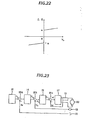
- a servo motor control apparatus comprising a positional feedback loop is generally provided with a speed feedback loop for controlling a speed of revolution of motor 10 and a current feedback loop for controlling a current of motor 10, in addition to a positional feedback loop for controlling position of revolution of motor 10 or position of mechanical movable part (not shown).
- control is carried out so that deviation ⁇ I between a motor current I d detected by a resistor 11 and a current command value Is sent from a proportional integral controller 12 becomes zero, while in the speed feedback loop, deviation (Ve) between a motor speed v d detected by speed detector such as a tachometer and a speed command value V s sent from D/A converter 14 becomes zero.
- position of motor is controlled by a positional feedback loop so that difference between position of motor t d detected by position detector 15 such as a resolver or linearscale, etc. and a position command value is given from a command pulse generating circuit 16.
- position detector 15 such as a resolver or linearscale, etc.
- a position command value is given from a command pulse generating circuit 16.
- 17 is amplifier; 18a - 18c are adders.
- Fig. 2 4 is an electrical circuit which indicates a conventional structure including an adder 18b, a proportional integral controller 12 and an adder 18c shown in Fig. 23.
- An operational amplifier Q 1 , resistors R l - R 4 and a capacitor C 1 form an adder 18b and a proportional integral controller 12, while an operational amplifier Q 2 and resistors R 5 - R 8 form an adder 18c.
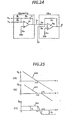
- Relationship among a motor current I d , a motor speed command V s and a motor speed V d in a conventional servo motor control apparatus having the structure shown in Fig. 23 when the rotating direction of motor is inversed can be indicated, for example, as the curves 30v r , 31v and 32i of Fig. 25, where motor current I d , motor speed command V s and motor speed V d are plotted on the vertical axis and the time t on the horizontal axis with the direction inversion command input time located at the origin.
- I 0 is a value of friction torque of machine converted in terms of a motor current.
- a speed command is reduced with a constant deceleration from the positive to negative direction.
- This m,ethod is intended to enhance control accuracy through compensation for response lag of motor caused by a friction torque when the motor changes the rotating direction.
- a voltage determining a current command value when the direction inversion signal is input is proportional to a friction torque
- a compensating voltage which is almost equal to such voltage in the absolute value and has polarity opposed to it is generated and this compensating voltage quickly presets, immediately after the direction inversion signal is input, a voltage forming said command current value to a voltage corresponding to a frictional torque.
- Fig. 27 shows an electrical circuit based on such improvement and the like symbols indicate the like elements in Fig. 24 and Fig. 27.
- 50 is compensating voltage generating circuit; 51 is response compensating circuit; IN 2 is input terminal to which peak value set signal S 1 is applied; IN 3 is input terminal to which a friction torque compensating signal S 2 is applied; OUT is output terminal from which a current command value Is is applied to the adder 18c in Fig. 23; Q 4 - Q 6 are operational amplifiers in the polarities shown in the figure; SW 1 , SW 2 are switching elements; R 10 - R 18 are resistors; C 2 is capacitor. Moreover, -V s is an output obtained when V s is applied to an inversion amplifier of -1.
- This circuit is different from a conventional apparatus shown in Fig. 24 in the point that the compensating voltage generating circuit 50 and the response compensating circuit 51 are provided.
- the compensating voltage generating circuit 50 detects, when a motor rotating direction inversion signal is output from a command pulse generating circuit 16 in the numerical control apparatus, a voltage which determines a current command value at this time, namely an output voltage (hereinafter referred to as a command voltage) of a proportional integral controller 12 and generates a compensating voltage V c which is almost equal to such command voltage in the absolute value and has the polarity opposed to it.
- This circuit is composed of an integral circuit consisting of a resistor R 14 and a capacitor C 2 , a switching element SW 1 which controls operation of such integral circuit and a polarity inversion circuit consisting of the operational amplifiers Q4 , Q5 and resistors R 13 , Ris, R 17 .
- the response compensating circuit 51 operates so that a command voltage is quickly set almost equal to a compensating voltage immediately after the motor rotating direction inversion command signal is input, and is composed of an operational amplifier Q 6 which amplifies difference between command voltage and compensating voltage V c and a switching element SW 2 which feeds back ⁇ V which is an output of such amplifier to the input side of proportional integral controller 12.
- Fig. 28 shows a diagram illustrating signal waveforms at respective points when the apparatus of Fig. 27 operates. With reference to the same figure, operations of apparatus of Fig. 27 are explained in details.
- a direction inversion signal like Fig. 28(a) is output, for example, from a command pulse generating circuit 23, a peak value set signal S 1 in duration T 2 , of which rising edge almost matches the rising part of direction inversion signal shown as Fig. 28(b), is generated by a control circuit (not shown).
- This peak value set signal S l is applied to the switching element SW 1 of the compensating voltage generating circuit 50, turning ON this switching element SW 1 only during the time T 2 .
- T 2 of peak value set signal S 1 is set to about 2t 3t, a compensating voltage which is almost equal to the command voltage in the absolute value and is opposed thereto in the polarity can be obtained, for example, as shown in Fig. 28(c) from the compensating voltage generating circuit 50 and this compensating voltage is also held even after the switching element SW 1 turns OFF.
- a frictional torque compensating signal 5 2 having duration T 3 which rises in synchronization with fall of the peak value set signal S l as shown in Fig. 28 (d) is generated by a control circuit not shown and it is applied to the switching element SW 2 of response compensating circuit 51, turning it on.
- the command voltage is controlled to feedback to become almost equal to the compensating voltage V c with the output of the operational amplifier 0 6 which amplifies a difference between the command voltage and compensating voltage V c and thereby the command voltage immediately falls as shown in Fig. 28(e) (however, rises immediately in the case of opposed direction inversion).
- compensation speed of command voltage can be freely changed by adjusting a value of resistor R 12 .
- a motor current I d exceeds the opposite friction torque Io quicker than the conventional circuit with operation of the compensating function and the motor speed also rises quicker as much and thereby time lag due to inversion of rotating direction of motor can be improved remarkably.
- time lag due to the inversion of rotating direction can be changed freely by adjusting a value of resistor R 12 .
- the apparatus disclosed in the Japanese Patent Provisional Publication No. 57-71282 is certainly capable of improving a time lag of servo system due to a frictional torque for the conventional servo motor control apparatus but also provides following disadvantages.
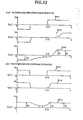
- relationship among a motor current I d at the initial condition, a motor speed command Vs and a motor speed V d in the conventional servo motor control apparatus having the structure shown in Fig. 23 can be indicated, for example, as Fig. 33 (a),(b) depending on the preceding positive or negative rotations before stoppage, where motor current I d , motor speed command Vs and motor speed V d are plotted on the vertical axis, while time t on the horizontal axis with the direction inversion command input time located at the origin.
- the curves 30v r , 3lv d , 32i d indicated by (al), (bl), (a2), (b2), (a3), (b3) respectively represent motor speed command, motor speed and motor current.
- a servo motor is assumed as to rotate in accordance with a current command Is and Is is omitted.
- I o is a frictional torque of machine and a torque corresponding to the external works;
- I l is static frictional torque of machine;
- 1 2 is a frictional torque where a torque corresponding to external work and acceleration torque are respectively converted in terms of a motor current.
- a motor rotation command output starts in the positive direction.
- Fig. 25 is an example where motor rotating direction is inversed in case the acceleration and deceleration torques can be disregarded. Each symbol is the same as that in Fig. 33 and a speed command is reduced at a constant acceleration to negative from positive direction.
- Such time lag and vibration are naturally appearing as the machining error in numerical control. More specific, following discrepancy is generated, namely, since cutting is started, for example, after eliminating the vibration shown in Fig. 34, dwelling of a constant time is required, or as shown in Fig. 26, cutting should be done along a true circle shown in Fig. 40 through distribution of command pulse trains of true circle but the shape of actual work has extruded portions as shown by a curve 41 at the quadrant changing portion of circular cutting because of a response lag when the rotating direction is inversed.
- a straight line 18 in Fig. 34 indicates a position command, while a curve 8 d indicates a position of actual motor or movable part of machine.
- the present invention is intended to solve the problems of a conventional control circuit shown in F ig. 24 explained above and the method proposed in the Japanese Patent Provisional Publication No. 57-71282 shown in Fig. 2 7 . It is the primary object of the present invention to enhance control accuracy by compensating for response lag of motor caused by a frictional torque when the motor rotating direction is inversed. It is the second object of the present invention to apply a motor control conforming to the primary object to a digital speed loop. Moreover, it is the third object of the present invention to enhance control accuracy by reducing response lag of motor caused by a frictional torque when the motor rotating direction is inversed.
- the means for solving such disadvantages of the prior art can be attained by reversely connecting to an integral capacitor immediately after the rotating starts or direction inversion signal is input and a current command value is momentarily set to a voltage corresponding to a frictional torque, or the integral capacitor is momentarily charged in the motor rotating direction with charge corresponding to a sum of a frictional torque, a torque corresponding to external work and an acceleration torque, utilizing that a voltage determining a current command value when rotation starts and a direction inversion signal is input is equal to a voltage which is proportional or corresponds to a sum of a frictional torque, a torque corresponding to external work and an acceleration torque, and in this case since speed command and a motor speed are almost zero, a voltage determining a current command value is equal to a voltage across the integral capacitor.
- the means of the present invention can be achieved by setting the integral item of controller to a prescribed value at the timing mentioned above.
- Fig. 1 is an example, for example, of 2-axes X-Y table control apparatus for implementing the present invention.
- 200 denote a numerical control apparatus
- 210 is a command function generator
- 220 is an X-axis motor controller
- 230 is an Y-axis motor controller
- 240 is a cutting machine
- 10X is an X-axis motor
- 10Y is an Y-axis motor.
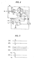
- Fig. 2 is an electrical circuit of the essential part illustrating the structure of the apparatus of the embodiment achieving said first object of the present invention.
- the same symbols as those in Fig. 24 denote the same elements.
- 80 denotes an integral capacitor connection inversion circuit
- IN 1 is an input terminal to which the direction inversion signal pulse is applied.
- the apparatus of this embodiment is different from the conventional apparatus shown in Fig. 24 in the point that an integral capacitor connection inversion circuit 80 is provided.
- the integral capacitor connection inversion circuit 80 momentarily inverses connection of the integral capacitor C 1 when the motor rotating direction inversion signal is output from the command function generator 210 of the numerical control apparatus 200 and is composed of a NOT gate IC l , a J-K flip-flop IC 2 and transfer type analog switches SW 3 , SW 4 .
- Fig. 3 shows waveforms at each point in such a case that the circuit shown in Fig. 2 operates. Operations of circuit shown in Fig. 2 are explained in detail with reference to Fig. 3.
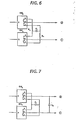
- Fig. 4 two units of one-make type analog switch or reed switch can be used as shown in Fig. 4, in place of one transfer type analog switch or reed switch.
- IC 3 is a NOT gate
- SWs, SW 6 are one-make type analog switch or reed switch.
- the block 90 shown in Fig. 4 corresponds to SW 3 in Fig. 2 and the block 91 to SW 4 of Fig. 2.
- two units of two-make type analog switch or reed switch may be used as shown in Fig. 5 in place of two transfer type analog switches or reed switches.
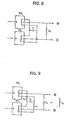
- a switch shows a certain lag of operation and the closing time of switch is generally different from the opening time.
- the closing time of switch is quicker than the opening time, there is a fear in the circuit of Fig. 2 that the integral capacitor is transitionally discharged through the short-circuitting.
- a resistor R a having a selected value is inserted as shown in Fig. 6 so that a time constant ClRa becomes sufficiently larger than the short-circuit time.
- a capacitor C 2 having sufficiently sm.aller capacitance value than C l is inserted to the terminals 1 and 2 or a high resistance R b is inserted to the terminals 1 and 2 as shown in Fig. 8.
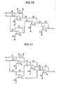
- Fig. 10 and Fig. 11 respectively show the structures of the integral proportional controller and integral proportional differential controller.
- the present invention can also be applied to these control systems as in the case of the proportional integral controller as explained above with the similar effect by separating the integral capacitor C shown in such figures and then connecting a capacitor polarity inversion circuit shown in Fig. 12 to the terminals 1 and 2.
- the moment of polarity judgment of speed command Vs is preferably seized equivalently as the motor rotating direction inversion signal pulse.
- a command voltage which is equal in the absolute value and is opposed in polarity to a command voltage which determines a current command value in the moment when the motor rotating direction inversion signal pulse is input from the command function generator is generated and the command voltage corresponding to a frictional torque is compensated momentarily, thereby remarkably improving delay of servo system due to frictional torque.
- circuit structure is simplified as comparison with the method disclosed in the Japanese Patent Provisional Publication No. 57-71282 and response lag can be reduced theoretically to zero.
- tne servo motor control circuit in which the speed loop is controlled digitally, having the position feedback loop is provided, as shown for example in Fig. 30, with a speed feedback loop for controlling rotating speed of motor 21 and a current feedback loop for controlling a current of motor 21, in addition to said position feedback loop for controlling rotating position of motor 21 or position of movable part of machine (not shown).
- control is made so that a motor current I d detected by a current detector 20 becomes equal to a motor current command value I s ' in analog amount and difference between a motor speed V d detected by a speed detector 15 and a speed command value V s sent from a speed command operation unit 13 becomes zero.
- position of motor is controlled by the position feedback loop so that difference between the position l d detected by a position detector 22 such as pulse encoder or linear scale, etc. and a command value ⁇ s given from a command value generator 10.
- a position detector 22 such as pulse encoder or linear scale, etc.
- Fig. 30, 12 is a position counter
- 16 is a current command operation unit
- 17 is a D/A converter
- 19 is a power amplifier
- 11, 14, 18 are substractors.
- the part enclosed by a broken line is digitally processed.
- the thick arrow mark indicates a digital signal, while a thin arrow mark ( - ) indicates an analog signal.
- arithmetic operation indicated below is usually carried out.
- This current command operation system is the PI (proportional integral) control system.
- Fig. 31 shows a current command operation unit .16' which determines relationship among speed command V s , speed V d and current command Is in the I-P (integral-proportional) control system.
- the current command operation unit 16' carries out following arithmetic operations.
- Fig.32 shows an example where I SI in the equation (2) is realized in the hardware circuit.
- 51 is an adder and 52 is a memory which latches an input A at the rising edge of the signal input to the CK terminal and sends such value as the output B.
- IN 1 is responsive to a clock pulse for generating the timing of arithmetic operation and a pulse train signal having a constant period is usually input thereto.
- Fig. 13 shows an embodiment of the present invention.
- the elements given the like symbols as those of Fig. 32 have the like functions.
- 63 is a counter, where Up is a count-up pulse input terminal, LD is a load pulse input terminal, PR is a preset value input terminal and S is a counter sign bit.
- a preset value p R is set to -1 and -1 is set to the counter at the rising edge of pulse to be applied to IN 2 (load signal input terminal).
- a clock pulse is input to IN 1 , F namely -I SI is latched by the memory 52, counting up the counter 63 to 0.
- V S - V d is input in place of V e of Fig.13 and the structure and function are realized in the same way.
- the moment of polarity inversion of speed command V s is seized and equivalently used as the motor rotating direction inversion signal pulse.
- the embodiment of the present invention shown in Fig. 13 generates a current command value which is equal in the absolute value and is opposed in polarity to a current command value at that time and momentarily compensates for a motor current corresponding a frictional torque in the moment that the motor rotating direction inversion signal pulse is input from the command function generator.
- the embodiment is capable of extraordinarily improving a lag of servo system by frictional torque. Accordingly, machining error as shown in F ig. 26 can be eliminated and the machining accuracy can also be improved by adopting the present invention into the servo motor -control apparatus of the numerical control system.
- Fig. 14 is a circuit diagram illustrating a structure of an embodiment of the present invention. The same elements as those in Fig. 24 are given the same symbols.
- IN 1 is an input terminal to which the motor rotating direction inversion signal pulse is applied. This embodiment is different from the conventional apparatus in such a point that a relay R which turns ON and OFF with the direction inversion signal pulse IN l is provided.
- Fig. 15 shcws signal waveforms at each point in case the circuit shown in Fig. 14 is operated. Operations of the circuit shown in Fig. 14 are explained in detail with reference to the same figure.
- Short-circuit of integral capacitor means a proportional control of speed loop, and it can be short-circuitted or not by switching the proportional control and proportional integral control. It is known that when an integral capacitor is saturated, a motor vibrates remarkably, and such control can also be mixed in parallel to the control system of short-circuitting the integral capacitor in order to stop such vibration.
- the moment of polarity inversion of speed command V s is seized and is equivalently used as the motor rotating direction inversion signal pulse.
- the embodiment of the present invention shown in Fig. 14 provides the effect of reducing a delay at the time of inversing rotating direction of motor to a half with only such a simple method that the integral capacitor of speed amplifier is short-circuitted in the moment that the motor rotating direction inversion signal pulse is input from the command function generator.
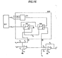
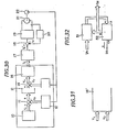
- Pig. 16 is a circuit diagram illustrating a structure of the embodiment of the present invention. The elements same as those in Fig. 14 are given the same symbols.
- Q c is a terminal for supplying charges corresponding to speed to the D/A converter 71 from the command function generator.
- IN 1 is an input terminal to which a signal pulse is applied when the motor starts to rotate and changes its rotating direction.
- RE 1 , RE 2 are relays for transfer of contacts with the signal pulse sent from the terminal IN I .
- the apparatus of this embodiment is different from the conventional apparatus shown in Fig. 14 only in such a point that an integral capacitor charge circuit 100 is provided.
- the integral capacitor charge circuit 100 momentarily charges an integral capacitor when the motor rotation start signal or rotating direction inversion signal are output from the command function generator of the numerical control system.
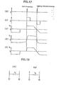
- Fig. 17 shows signal waveforms at respective points when the circuit shown in Fig. 16 is operated. Operations of the circuit shown in Fig. 16 are explained in detail with reference to the same figure.
- the present invention is capable of steeply improving a lag of servo system due to frictional torque and acceleration torque because a command voltage determining a current command value at that time can be set freely in the moment that the motor rotation start pulse and direction inversion pulse is input from the command function generator.
- vibration of motor at the time of starting rotation shown in Fig. 34 and machining error shown in Fig. 26 can be eliminated and improvement in machining accuracy and quick response of motor are effectively attained by adopting the present invention to the servo motor control apparatus of the numerical control system.
- FIG. 19 an integral capacitor charge circuit 100 used in case a command voltage which determines a current command value is set constant is shown in Fig. 19.
- 41, 42, 43 are relays which operate as in the case of Fig. 16.
- 44 is an OR circuit.
- 45, 46 are operational amplifiers.
- the signal pulse is input from the terminal IN 1 .
- the contacts of relays 41, 43 are connected to the side [a], while contacts of relay 42 is connected to the side [b] when the signal pulse rises. Therefore, the capacitor C l charged up to [R 1 /(R 1 + R 2 )] V c [Volt] by an output voltage of the operational amplifier 45.
- Switching by relay may be replaced with an electronic switching by a variety of analog switches.
- B 1 is an inversion circuit.
- B 2 , H 3 , B 6 , B 7 are AND circuits.
- B 4 , B 5 are retriggerable monostable multi-vibrators.
- Bg, Bg are monostable multi-vibrators.
- PULSE is a speed command signal pulse.
- SIGN is an input terminal of speed command direction.
- IN 1 , IN 2 are output terminals of signal pulses when the motor starts rotation in the positive or negative direction and the motor changes its rotating direction.
- the embodiments of the present invention shown in Fig. 16 - Fig. 20 provide the effect that control accuracy can be enhanced by compensating for vibration and response lag of motor caused by frictional torque and acceleration torque when the motor starts rotation and changes its rotating direction.
- F ig. 21 shows an example where I SI of equation (2) is realized with a hardware circuit.
- Cl, C2 are function generators which respectively determine the integral items of speed loop as the functions of speed command Vs when the motor starts rotation or changes its rotating direction.
- C3 is an OR gate which generates logical sum of the sign bits S1, S2 of counters 63-1, 63-2.
- V s - V d is input in place of V e of Fig. 21 and therefore the structure and function can also be realized in the same way.
- the moment of polarity inversion of speed command V s is preferably seized to equivalently use as the motor rotating direction inversion signal pulse.
- the embodiment of the present invention shown in Fig. 21 can remarkably improve the lag of servo system due to frictional torque because an integral item of controller is set to a value having the polarity and amplitude corresponding to the speed command in the moment that the motor operation start or direction inversion signal is input and a motor current corresponding to frictional torque is momentarily compensated.
- the present invention can be applied in various fields where high resolution is required for servo mechanism such as the machining by sophisticated machineries, manufacturing of semiconductor devices and machining for non-spherical surface lens.
Landscapes
- Engineering & Computer Science (AREA)
- Human Computer Interaction (AREA)
- Manufacturing & Machinery (AREA)
- Physics & Mathematics (AREA)
- General Physics & Mathematics (AREA)
- Automation & Control Theory (AREA)
- Control Of Position Or Direction (AREA)
- Control Of Electric Motors In General (AREA)
Applications Claiming Priority (8)
| Application Number | Priority Date | Filing Date | Title |
|---|---|---|---|
| JP271554/84 | 1984-12-22 | ||
| JP59271553A JPS61150689A (ja) | 1984-12-22 | 1984-12-22 | 摩擦トルクを補償するサ−ボモ−タ制御方法 |
| JP271552/84 | 1984-12-22 | ||
| JP59271552A JPS61150688A (ja) | 1984-12-22 | 1984-12-22 | 摩擦トルクを補償するサ−ボモ−タ制御方法 |
| JP59271554A JPS61150690A (ja) | 1984-12-22 | 1984-12-22 | サ−ボモ−タの制御方法 |
| JP271553/84 | 1984-12-22 | ||
| JP1212585A JPS61173684A (ja) | 1985-01-24 | 1985-01-24 | 摩擦トルクを補償するサ−ボモ−タ制御方法 |
| JP12125/85 | 1985-01-24 |
Publications (2)
| Publication Number | Publication Date |
|---|---|
| EP0207166A1 true EP0207166A1 (de) | 1987-01-07 |
| EP0207166A4 EP0207166A4 (de) | 1989-06-21 |
Family
ID=27455733
Family Applications (1)
| Application Number | Title | Priority Date | Filing Date |
|---|---|---|---|
| EP19860900261 Withdrawn EP0207166A4 (de) | 1984-12-22 | 1985-12-21 | Verfahren und vorrichtung zur regelung eines servomotors. |
Country Status (5)
| Country | Link |
|---|---|
| US (1) | US4743822A (de) |
| EP (1) | EP0207166A4 (de) |
| DE (1) | DE3590662T1 (de) |
| GB (1) | GB2180079B (de) |
| WO (1) | WO1986003904A1 (de) |
Cited By (3)
| Publication number | Priority date | Publication date | Assignee | Title |
|---|---|---|---|---|
| FR2613886A1 (fr) * | 1987-03-02 | 1988-10-14 | Yokogawa Electric Corp | Ensemble de moteur electrique a commande directe pour robot |
| FR2655942A1 (fr) * | 1989-12-20 | 1991-06-21 | Gen Electric | Dispositif de commande de la position d'un engin spatial avec compensation du frotttement d'une roue de reaction. |
| EP0313662A4 (en) * | 1987-04-30 | 1992-06-03 | Fanuc Ltd | Servo control circuit |
Families Citing this family (10)
| Publication number | Priority date | Publication date | Assignee | Title |
|---|---|---|---|---|
| JPS63148315A (ja) * | 1986-12-12 | 1988-06-21 | Fanuc Ltd | サ−ボモ−タ制御装置 |
| WO1990012448A1 (fr) * | 1989-04-10 | 1990-10-18 | Kabushiki Kaisha Yaskawa Denki Seisakusho | Dispositif de commande de servomoteur |
| JP3083870B2 (ja) * | 1991-05-10 | 2000-09-04 | ファナック株式会社 | 数値制御装置 |
| EP0666643B1 (de) * | 1994-02-04 | 1998-09-16 | Agfa-Gevaert N.V. | Unterdrückung der Schwingungen eines Schrittmotors durch Modulation des Vektorwinkels und der Vektorgrösse |
| JP3091388B2 (ja) * | 1995-04-19 | 2000-09-25 | ファナック株式会社 | モータの暴走検出方法および暴走検出装置 |
| JP3169838B2 (ja) * | 1996-08-21 | 2001-05-28 | 東芝機械株式会社 | サーボモータの制御方法 |
| US5721477A (en) * | 1997-02-11 | 1998-02-24 | The University Of Manitoba | Nonlinear proportional integral controller |
| KR100461186B1 (ko) * | 2002-10-23 | 2004-12-14 | 삼성전자주식회사 | 비례적분제어기의 제어방법 |
| JP4677037B2 (ja) * | 2009-01-20 | 2011-04-27 | ファナック株式会社 | バックラッシュを抑制するサーボ制御装置 |
| BR102013032677A2 (pt) * | 2012-12-19 | 2014-09-23 | Dow Agrosciences Llc | Transformação melhorada do feijão de soja para a produção do evento transgênico eficiente e de alto-rendimento |
Family Cites Families (3)
| Publication number | Priority date | Publication date | Assignee | Title |
|---|---|---|---|---|
| US3998409A (en) * | 1975-03-11 | 1976-12-21 | Rca Corporation | Minimization of spacecraft attitude error due to wheel speed reversal |
| JPS6033756Y2 (ja) * | 1979-01-26 | 1985-10-07 | 株式会社東芝 | モ−タ速度制御用サ−ボル−プ回路 |
| JPS5771282A (en) * | 1980-10-20 | 1982-05-04 | Fanuc Ltd | Servo motor controller |
-
1985
- 1985-12-21 EP EP19860900261 patent/EP0207166A4/de not_active Withdrawn
- 1985-12-21 WO PCT/JP1985/000701 patent/WO1986003904A1/ja not_active Ceased
- 1985-12-21 US US06/898,562 patent/US4743822A/en not_active Expired - Fee Related
- 1985-12-21 DE DE19853590662 patent/DE3590662T1/de not_active Withdrawn
- 1985-12-21 GB GB8622676A patent/GB2180079B/en not_active Expired
Cited By (3)
| Publication number | Priority date | Publication date | Assignee | Title |
|---|---|---|---|---|
| FR2613886A1 (fr) * | 1987-03-02 | 1988-10-14 | Yokogawa Electric Corp | Ensemble de moteur electrique a commande directe pour robot |
| EP0313662A4 (en) * | 1987-04-30 | 1992-06-03 | Fanuc Ltd | Servo control circuit |
| FR2655942A1 (fr) * | 1989-12-20 | 1991-06-21 | Gen Electric | Dispositif de commande de la position d'un engin spatial avec compensation du frotttement d'une roue de reaction. |
Also Published As
| Publication number | Publication date |
|---|---|
| EP0207166A4 (de) | 1989-06-21 |
| WO1986003904A1 (fr) | 1986-07-03 |
| GB8622676D0 (en) | 1986-10-22 |
| GB2180079A (en) | 1987-03-18 |
| GB2180079B (en) | 1989-03-30 |
| DE3590662T1 (de) | 1987-02-19 |
| US4743822A (en) | 1988-05-10 |
Similar Documents
| Publication | Publication Date | Title |
|---|---|---|
| EP0207166A1 (de) | Verfahren und vorrichtung zur regelung eines servomotors | |
| EP0051477A1 (de) | Verfahren und Einrichtung zur Spindelorientierungssteuerung | |
| KR100533608B1 (ko) | 동기전동기의 센서리스 제어장치 | |
| JPH03228106A (ja) | サーボモータの制御方法 | |
| US5231335A (en) | Double spindle synchronous driving apparatus | |
| EP0141860A1 (de) | Gerät für kontrolle des standes | |
| EP0034927B1 (de) | Steuergerät zur Spindelorientierung | |
| KR910006498B1 (ko) | 위치제어방식 | |
| SU1175357A3 (ru) | Устройство дл управлени остановом шпиндел в заданном положении | |
| US5144214A (en) | Numerical control system for moving work or cutter in synchronism with the rotation of a spindle | |
| KR880002557B1 (ko) | 가동부의 원점복귀 제어법 및 그 장치 | |
| JPH0232799A (ja) | 負荷角調整装置を有する電気ステツプモータ及びその作動方法 | |
| GB816360A (en) | Electric remote-control positioning system | |
| US3896361A (en) | Method and apparatus for compensating an error in numerical control | |
| SU1674058A1 (ru) | Релейно-импульсный регул тор | |
| EP0146849A2 (de) | Stellglied mit einer Schrittbewegungsfunktion | |
| Kim et al. | Accurate position control for AC servo motor using novel speed estimator | |
| KR930001582B1 (ko) | 원점 복귀방법 | |
| Yamazaki et al. | Development of flexible actuator controller for advanced machine tool and robot control | |
| JPS61150690A (ja) | サ−ボモ−タの制御方法 | |
| US3803469A (en) | System for controlling speed of the tape drive in a tape recording and replaying apparatus | |
| JPS61173684A (ja) | 摩擦トルクを補償するサ−ボモ−タ制御方法 | |
| SU1159146A1 (ru) | Дискретный замкнутый электропривод | |
| JP3301190B2 (ja) | 主軸運転切り換え方法 | |
| US2992374A (en) | Servosystem and relay circuit |
Legal Events
| Date | Code | Title | Description |
|---|---|---|---|
| PUAI | Public reference made under article 153(3) epc to a published international application that has entered the european phase |
Free format text: ORIGINAL CODE: 0009012 |
|
| AK | Designated contracting states |
Kind code of ref document: A1 Designated state(s): FR |
|
| 17P | Request for examination filed |
Effective date: 19861128 |
|
| EL | Fr: translation of claims filed | ||
| A4 | Supplementary search report drawn up and despatched |
Effective date: 19890621 |
|
| STAA | Information on the status of an ep patent application or granted ep patent |
Free format text: STATUS: THE APPLICATION IS DEEMED TO BE WITHDRAWN |
|
| 18D | Application deemed to be withdrawn |
Effective date: 19900713 |
|
| RIN1 | Information on inventor provided before grant (corrected) |
Inventor name: FUTAMI, SHIGERU Inventor name: KAKU, YASUHIKO Inventor name: YAMAMOTO, YOICHI |