EP0207408A1 - Procédé de commande de l'angle de phase du courant ou de la tension de sortie d'un onduleur et dispositif pour sa mise en oeuvre - Google Patents
Procédé de commande de l'angle de phase du courant ou de la tension de sortie d'un onduleur et dispositif pour sa mise en oeuvre Download PDFInfo
- Publication number
- EP0207408A1 EP0207408A1 EP86108484A EP86108484A EP0207408A1 EP 0207408 A1 EP0207408 A1 EP 0207408A1 EP 86108484 A EP86108484 A EP 86108484A EP 86108484 A EP86108484 A EP 86108484A EP 0207408 A1 EP0207408 A1 EP 0207408A1
- Authority
- EP
- European Patent Office
- Prior art keywords
- phase angle
- output current
- converter
- primary
- phase
- Prior art date
- Legal status (The legal status is an assumption and is not a legal conclusion. Google has not performed a legal analysis and makes no representation as to the accuracy of the status listed.)
- Granted
Links
- 238000000034 method Methods 0.000 title claims abstract description 11
- 230000001960 triggered effect Effects 0.000 claims description 3
- 238000010586 diagram Methods 0.000 description 3
- 230000001360 synchronised effect Effects 0.000 description 3
- 230000004913 activation Effects 0.000 description 2
- 230000001174 ascending effect Effects 0.000 description 2
- 230000001419 dependent effect Effects 0.000 description 1
- 230000010349 pulsation Effects 0.000 description 1
Images
Classifications
-
- H—ELECTRICITY
- H02—GENERATION; CONVERSION OR DISTRIBUTION OF ELECTRIC POWER
- H02M—APPARATUS FOR CONVERSION BETWEEN AC AND AC, BETWEEN AC AND DC, OR BETWEEN DC AND DC, AND FOR USE WITH MAINS OR SIMILAR POWER SUPPLY SYSTEMS; CONVERSION OF DC OR AC INPUT POWER INTO SURGE OUTPUT POWER; CONTROL OR REGULATION THEREOF
- H02M7/00—Conversion of AC power input into DC power output; Conversion of DC power input into AC power output
- H02M7/42—Conversion of DC power input into AC power output without possibility of reversal
- H02M7/44—Conversion of DC power input into AC power output without possibility of reversal by static converters
- H02M7/48—Conversion of DC power input into AC power output without possibility of reversal by static converters using discharge tubes with control electrode or semiconductor devices with control electrode
- H02M7/505—Conversion of DC power input into AC power output without possibility of reversal by static converters using discharge tubes with control electrode or semiconductor devices with control electrode using devices of a thyratron or thyristor type requiring extinguishing means
- H02M7/515—Conversion of DC power input into AC power output without possibility of reversal by static converters using discharge tubes with control electrode or semiconductor devices with control electrode using devices of a thyratron or thyristor type requiring extinguishing means using semiconductor devices only
- H02M7/525—Conversion of DC power input into AC power output without possibility of reversal by static converters using discharge tubes with control electrode or semiconductor devices with control electrode using devices of a thyratron or thyristor type requiring extinguishing means using semiconductor devices only with automatic control of output waveform or frequency
- H02M7/527—Conversion of DC power input into AC power output without possibility of reversal by static converters using discharge tubes with control electrode or semiconductor devices with control electrode using devices of a thyratron or thyristor type requiring extinguishing means using semiconductor devices only with automatic control of output waveform or frequency by pulse width modulation
- H02M7/529—Conversion of DC power input into AC power output without possibility of reversal by static converters using discharge tubes with control electrode or semiconductor devices with control electrode using devices of a thyratron or thyristor type requiring extinguishing means using semiconductor devices only with automatic control of output waveform or frequency by pulse width modulation using digital control
Definitions
- the invention relates on the one hand to a method for controlling the phase angle of the output current of a converter with a DC intermediate circuit, wherein an inverter part of the converter has six electronic switches arranged in a three-phase bridge circuit, which can be controlled in pairs in six possible switching combinations, each of which is one natural multiples of 60 ° el are assigned to the corresponding primary phase angle, each setpoint for the phase angle of the output current being fed to a control unit for the inverter, which detects the two primary phase angles which are immediately adjacent to the phase angle of the output current and the switching combinations assigned to them with an alternating cycle switches back and forth that the phase angle of the output current corresponds to the specified setpoint.
- the invention relates to a method for controlling the phase angle of the output voltage of a converter with a DC link, wherein an inverter part of the converter has six electronic switches arranged in a three-phase bridge circuit, which can be controlled in groups of three in six possible switching combinations, each of which is associated with a natural multiple of 60 ° el corresponding primary phase angle and can be triggered by the at least one further switching combination which corresponds to a de-energized state, each setpoint for the phase angle of the Output voltage is supplied to a control unit for the inverter part, which detects the two primary phase angles, which are directly adjacent to the phase angle of the output voltage, and switches the switching combinations assigned to them with an alternating cycle so that the phase angle of the output voltage corresponds to the specified setpoint.
- the period of the alternating cycle is either kept constant (free running) or chosen so that the period represents a natural fraction of the period of the converter frequency (synchronous pulsing).
- minimum pulse times must be observed due to the finite commutation times of the electronic switches or the power section. If these minimum pulse times are not adhered to, the corresponding pulses must be suppressed, which leads to deviations from the desired current or. Voltage curve leads.
- the object of the invention is to develop a method of the type mentioned at the outset such that the minimum pulse times are maintained even with a small pulse-pause ratio, so that the concentricity is improved by machines connected downstream from the converter.
- this object is achieved for converters with a DC link in that the period of the alternating cycle is controlled by the setpoint for the phase angle in such a way that the period of an output current with its phase angle centrally between two primary phase angles has a minimum value and the period of one with its Phase angle has a maximum value corresponding to a primary phase angle output current.
- this task is solved for converters with a DC link in that the period of the alternating cycle is controlled by the setpoint for the phase angle in such a way that the period of an output voltage with its phase angle centrally between two primary phase angles has a minimum value and the period has one with output phase corresponding to a primary phase angle has a maximum value.
- An advantageous embodiment of the invention is characterized in that the period is linear with the phase angle from the minimum value to the immediately adjacent maximum value. This results in a simple relationship between the phase angle and the period, which can easily be implemented in terms of circuitry.
- a device for carrying out the method is characterized in that a first control voltage which is linearly proportional to the position of the phase angle between two immediately adjacent primary phase angles can be fed to the first input of a comparator for a greater-smaller comparison, that an alternating voltage is supplied to the second input as the second control voltage of the comparator can be fed, the frequency of which can be wobbled in a triangular manner in accordance with the position of the phase angle, and that, according to the comparison result, control signals from the comparator can be used to trigger the alternating clock for switching the primary phase angle adjacent to the phase angle of the output current or the output voltage.
- An advantageous embodiment of the above-mentioned device is designed so that the frequency swing of the second control voltage can be increased as the converter frequency falls. As a result, even with a low frequency converter can still be keyed enough frequently within a 60 ° el sector in order to reproduce the desired target value by keying.
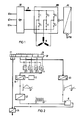
- FIG. 1 shows a rectifier GR which is fed by a three-phase mains voltage via terminals K1, K2 and K3.
- the direct current fed out by the rectifier GR is fed to an inverter WR as an intermediate circuit direct current via a choke D.
- This basically consists of six electronic switches 1 to 6 arranged in a three-phase bridge circuit.
- switches 1 to 6 which are operated in pairs, six possible switching combinations can be realized, which serve to enable a three-phase motor M to be controlled with an output current of a predetermined phase angle. Natural multiples of 60 ° el are achieved by setting one of the six possible switching combinations. In the exemplary embodiment, closing of switches 1 and 6 is shown, for example, so that in this case the current is conducted in accordance with the current path drawn with solid lines.
- phase angles of the output current differing from these primary phase angles can be realized, this is done by alternately setting adjacent primary phase angles and thus switching back and forth in in accordance with the pulse-pause ratios specified according to the phase angle to be set.
- the activation of the switches 1 to 6 results in an activation unit AE, to which the respective setpoint for the phase angle of the output current of the converter is fed on the input side.
- a basic training possibility of the control unit AE is shown in the illustration according to FIG. 2.
- the setpoint for the phase angle is impressed in digital form in a memory SP.
- This memory SP is divided into individual cells Z1 to Z8, of which the cells Z1 to Z3 contain a characteristic number for the respective sector between the possible primary phase angles and the cells Z4 to Z8 indicate the respective angle between the primary phase angles.
- the angle between two primary phase angles could be divided into 32 binary steps, which are cyclically run through from sector to sector.
- the contents of the memory cells Z4 to Z8 arrive at a first digital-to-analog converter U3, which generates a sawtooth-shaped analog signal for 60 ° el each time the binary number space is passed through, as is indicated diagrammatically below the converter U3.
- This analog signal reaches the non-inverting input of a comparator K provided as a larger-smaller comparator as the first control voltage.
- the contents of the memory cells Z5 to Z8 are each fed to a first input of exclusive-OR gates E1 to E4, the second input of which is connected to the memory cell Z4.
- the outputs of the exclusive-OR elements E1 to E4 to a digital-to-analog converter U1 make a binary number 00000 ascending in the memory cells Z4 to Z8 ascending to the binary number 01111 and from the binary number 10,000 binary sequence (0000 to 1111 to 0000) falling down to the binary number 11111 is generated.
- the converter U1 generates a voltage signal which is proportional to the binary number supplied, the conversion factor being determined with the aid of an encoder G in such a way that the resulting output voltage is increased as the converter frequency falls.
- the output signal of the converter U1 (indicated in a diagram immediately below the converter) reaches a converter U2 which is designed as a voltage-frequency converter.
- An alternating voltage signal is generated by the converter U2 as a second control voltage, which is fed to the inverting input of the comparator K.
- This second control voltage is indicated as a diagram below the converter U2.
- the frequency swing of the second control voltage is determined by the amplitude of the output signal of the converter U1.
- the sector number of the respectively predetermined phase angle reaches a converter U4 via a bus system from the memory SP.
- the sector number is used to determine which two adjacent primary phase angles are to be assigned to this sector number.
- these primary phase angles are clocked.
- a corresponding control signal then passes from the converter U4 to the inverter according to FIG. 1 in order to actuate the switches 1 to 6.
- the number of pulsations per sector should be related in relation to the throughput time for a sector.
- the resulting average pulse frequency could then be converted using the converter frequency can be synchronized. It is also possible to combine the circuit in accordance with the DE-OS mentioned at the beginning with an additional sine modulation.
- the amplitude of the output voltage can be influenced relatively easily by keying in the de-energized state.
Landscapes
- Engineering & Computer Science (AREA)
- Power Engineering (AREA)
- Inverter Devices (AREA)
- Control Of Voltage And Current In General (AREA)
- Control Of Motors That Do Not Use Commutators (AREA)
- Power Conversion In General (AREA)
Priority Applications (1)
| Application Number | Priority Date | Filing Date | Title |
|---|---|---|---|
| AT86108484T ATE52885T1 (de) | 1985-07-03 | 1986-06-20 | Verfahren zur steuerung des phasenwinkels des ausgangsstroms oder der ausgangsspannung eines umrichters und einrichtung zur durchfuehrung. |
Applications Claiming Priority (2)
| Application Number | Priority Date | Filing Date | Title |
|---|---|---|---|
| DE3523837 | 1985-07-03 | ||
| DE3523837 | 1985-07-03 |
Publications (2)
| Publication Number | Publication Date |
|---|---|
| EP0207408A1 true EP0207408A1 (fr) | 1987-01-07 |
| EP0207408B1 EP0207408B1 (fr) | 1990-05-16 |
Family
ID=6274877
Family Applications (1)
| Application Number | Title | Priority Date | Filing Date |
|---|---|---|---|
| EP86108484A Expired - Lifetime EP0207408B1 (fr) | 1985-07-03 | 1986-06-20 | Procédé de commande de l'angle de phase du courant ou de la tension de sortie d'un onduleur et dispositif pour sa mise en oeuvre |
Country Status (3)
| Country | Link |
|---|---|
| EP (1) | EP0207408B1 (fr) |
| AT (1) | ATE52885T1 (fr) |
| DE (1) | DE3671344D1 (fr) |
Citations (2)
| Publication number | Priority date | Publication date | Assignee | Title |
|---|---|---|---|---|
| DE3130672A1 (de) * | 1981-08-03 | 1983-02-17 | Siemens Ag | Verfahren zur steuerung des ausgangsstroms eines umrichters und schaltungsanordnung zur durchfuehrung des verfahrens |
| EP0106006A1 (fr) * | 1982-10-18 | 1984-04-25 | ELIN-UNION Aktiengesellschaft für elektrische Industrie | Procédé pour la prédétermination du vecteur courant statorique |
-
1986
- 1986-06-20 AT AT86108484T patent/ATE52885T1/de active
- 1986-06-20 EP EP86108484A patent/EP0207408B1/fr not_active Expired - Lifetime
- 1986-06-20 DE DE8686108484T patent/DE3671344D1/de not_active Expired - Lifetime
Patent Citations (2)
| Publication number | Priority date | Publication date | Assignee | Title |
|---|---|---|---|---|
| DE3130672A1 (de) * | 1981-08-03 | 1983-02-17 | Siemens Ag | Verfahren zur steuerung des ausgangsstroms eines umrichters und schaltungsanordnung zur durchfuehrung des verfahrens |
| EP0106006A1 (fr) * | 1982-10-18 | 1984-04-25 | ELIN-UNION Aktiengesellschaft für elektrische Industrie | Procédé pour la prédétermination du vecteur courant statorique |
Also Published As
| Publication number | Publication date |
|---|---|
| EP0207408B1 (fr) | 1990-05-16 |
| ATE52885T1 (de) | 1990-06-15 |
| DE3671344D1 (de) | 1990-06-21 |
Similar Documents
| Publication | Publication Date | Title |
|---|---|---|
| EP0762625A1 (fr) | Entraînement électrique | |
| DE69127664T2 (de) | Vorrichtung zur Erzeugung eines dreiphasigen PWM-Signals für Wechselrichter | |
| DE2843528C2 (fr) | ||
| DE3213057A1 (de) | Verfahren und anordnung zum regeln eines arbeitsstroms | |
| DE3007629A1 (de) | Verfahren und anordnung zur erzeugung eines dreiphasendrehstromes durch wechselrichten | |
| DE2045971A1 (de) | Schaltungsanordnung zur Erzeugung eines mehrphasigen Wechselstroms | |
| DE2323826B2 (fr) | ||
| DE2948946C2 (fr) | ||
| DE2514557C3 (de) | Einrichtung zur Steuerung der Lage des Ständerstromvektors einer umrichtergespeisten Drehfeldmaschine | |
| DE2151588A1 (de) | Ruhender Leistungswechselrichter | |
| DE69027247T2 (de) | Leistungsregelungsvorrichtung für Heizelemente | |
| DE2653871C2 (de) | Anordnung zur Erzeugung von Wechselspannung mit einem Asynchrongenerator | |
| DE69207035T2 (de) | Pulsbreiten-moduliertes Wechselrichterssteuerungssystem | |
| EP0207408B1 (fr) | Procédé de commande de l'angle de phase du courant ou de la tension de sortie d'un onduleur et dispositif pour sa mise en oeuvre | |
| EP0153488A1 (fr) | Procédé de production, d'injection et de transmission de signaux dans un réseau de distribution électrique basse tension | |
| DE2445162B2 (de) | Einphasenasynchronmotor mit einem Käfigläufer | |
| EP0198204B1 (fr) | Procédé et dispositif pour convertir du courant continu en courant alternatif | |
| DE2361649B2 (de) | Abtastvorrichtung für eine elektrische Kopiersteuerungsvorrichtung | |
| DE2756952C3 (de) | Digitaler Steuersatz für einen selbstgeführten Stromrichter | |
| EP0142649A2 (fr) | Procédé et dispositif pour la commande de commutateurs dans un onduleur polyphasé, en particulier dans un onduleur à transistors | |
| EP0106006B1 (fr) | Procédé pour la prédétermination du vecteur courant statorique | |
| DE69023918T2 (de) | Wechselstromantriebsreglung mit veraenderlicher geschwindigkeit. | |
| DE2539692C2 (de) | Digitales Verfahren zum Erzeugen von Signalspannungen und Anordnung zur Durch- führung des Verfahrens | |
| DE3542753C2 (fr) | ||
| DE2850539A1 (de) | Verfahren und schaltungsanordnung zur steuerung eines elektrischen schrittmotors |
Legal Events
| Date | Code | Title | Description |
|---|---|---|---|
| PUAI | Public reference made under article 153(3) epc to a published international application that has entered the european phase |
Free format text: ORIGINAL CODE: 0009012 |
|
| AK | Designated contracting states |
Kind code of ref document: A1 Designated state(s): AT CH DE LI |
|
| 17P | Request for examination filed |
Effective date: 19870205 |
|
| 17Q | First examination report despatched |
Effective date: 19840407 |
|
| GRAA | (expected) grant |
Free format text: ORIGINAL CODE: 0009210 |
|
| AK | Designated contracting states |
Kind code of ref document: B1 Designated state(s): AT CH DE LI |
|
| REF | Corresponds to: |
Ref document number: 52885 Country of ref document: AT Date of ref document: 19900615 Kind code of ref document: T |
|
| REF | Corresponds to: |
Ref document number: 3671344 Country of ref document: DE Date of ref document: 19900621 |
|
| PLBE | No opposition filed within time limit |
Free format text: ORIGINAL CODE: 0009261 |
|
| STAA | Information on the status of an ep patent application or granted ep patent |
Free format text: STATUS: NO OPPOSITION FILED WITHIN TIME LIMIT |
|
| 26N | No opposition filed | ||
| PGFP | Annual fee paid to national office [announced via postgrant information from national office to epo] |
Ref country code: AT Payment date: 19920529 Year of fee payment: 7 |
|
| PGFP | Annual fee paid to national office [announced via postgrant information from national office to epo] |
Ref country code: CH Payment date: 19920914 Year of fee payment: 7 |
|
| PG25 | Lapsed in a contracting state [announced via postgrant information from national office to epo] |
Ref country code: AT Effective date: 19930620 |
|
| PG25 | Lapsed in a contracting state [announced via postgrant information from national office to epo] |
Ref country code: LI Effective date: 19930630 Ref country code: CH Effective date: 19930630 |
|
| REG | Reference to a national code |
Ref country code: CH Ref legal event code: PL |
|
| PGFP | Annual fee paid to national office [announced via postgrant information from national office to epo] |
Ref country code: DE Payment date: 19950818 Year of fee payment: 10 |
|
| PG25 | Lapsed in a contracting state [announced via postgrant information from national office to epo] |
Ref country code: DE Effective date: 19970301 |