EP0106006A1 - Procédé pour la prédétermination du vecteur courant statorique - Google Patents
Procédé pour la prédétermination du vecteur courant statorique Download PDFInfo
- Publication number
- EP0106006A1 EP0106006A1 EP82890149A EP82890149A EP0106006A1 EP 0106006 A1 EP0106006 A1 EP 0106006A1 EP 82890149 A EP82890149 A EP 82890149A EP 82890149 A EP82890149 A EP 82890149A EP 0106006 A1 EP0106006 A1 EP 0106006A1
- Authority
- EP
- European Patent Office
- Prior art keywords
- alpha
- positions
- pointer
- discrete
- pulse
- Prior art date
- Legal status (The legal status is an assumption and is not a legal conclusion. Google has not performed a legal analysis and makes no representation as to the accuracy of the status listed.)
- Granted
Links
- 238000000034 method Methods 0.000 title claims abstract description 17
- 230000010355 oscillation Effects 0.000 claims abstract description 26
- 230000015654 memory Effects 0.000 claims description 2
- 230000029305 taxis Effects 0.000 claims 1
- 230000004907 flux Effects 0.000 abstract description 6
- PMGQWSIVQFOFOQ-YKVZVUFRSA-N clemastine fumarate Chemical compound OC(=O)\C=C\C(O)=O.CN1CCC[C@@H]1CCO[C@@](C)(C=1C=CC(Cl)=CC=1)C1=CC=CC=C1 PMGQWSIVQFOFOQ-YKVZVUFRSA-N 0.000 abstract 3
- 238000010586 diagram Methods 0.000 description 6
- 238000004804 winding Methods 0.000 description 3
- 239000003990 capacitor Substances 0.000 description 2
- 230000008859 change Effects 0.000 description 2
- 230000001419 dependent effect Effects 0.000 description 2
- 230000000694 effects Effects 0.000 description 2
- 238000000819 phase cycle Methods 0.000 description 2
- 230000009467 reduction Effects 0.000 description 2
- 230000006978 adaptation Effects 0.000 description 1
- 230000001174 ascending effect Effects 0.000 description 1
- 230000007423 decrease Effects 0.000 description 1
- 230000003247 decreasing effect Effects 0.000 description 1
- 238000005315 distribution function Methods 0.000 description 1
- 230000006870 function Effects 0.000 description 1
- 238000009499 grossing Methods 0.000 description 1
- 230000006872 improvement Effects 0.000 description 1
- 230000000737 periodic effect Effects 0.000 description 1
- 230000008569 process Effects 0.000 description 1
- 238000001228 spectrum Methods 0.000 description 1
- 230000001629 suppression Effects 0.000 description 1
Images


Classifications
-
- H—ELECTRICITY
- H02—GENERATION; CONVERSION OR DISTRIBUTION OF ELECTRIC POWER
- H02P—CONTROL OR REGULATION OF ELECTRIC MOTORS, ELECTRIC GENERATORS OR DYNAMO-ELECTRIC CONVERTERS; CONTROLLING TRANSFORMERS, REACTORS OR CHOKE COILS
- H02P21/00—Arrangements or methods for the control of electric machines by vector control, e.g. by control of field orientation
- H02P21/24—Vector control not involving the use of rotor position or rotor speed sensors
- H02P21/28—Stator flux based control
- H02P21/30—Direct torque control [DTC] or field acceleration method [FAM]
-
- H—ELECTRICITY
- H02—GENERATION; CONVERSION OR DISTRIBUTION OF ELECTRIC POWER
- H02P—CONTROL OR REGULATION OF ELECTRIC MOTORS, ELECTRIC GENERATORS OR DYNAMO-ELECTRIC CONVERTERS; CONTROLLING TRANSFORMERS, REACTORS OR CHOKE COILS
- H02P27/00—Arrangements or methods for the control of AC motors characterised by the kind of supply voltage
- H02P27/04—Arrangements or methods for the control of AC motors characterised by the kind of supply voltage using variable-frequency supply voltage, e.g. inverter or converter supply voltage
- H02P27/06—Arrangements or methods for the control of AC motors characterised by the kind of supply voltage using variable-frequency supply voltage, e.g. inverter or converter supply voltage using DC to AC converters or inverters
- H02P27/08—Arrangements or methods for the control of AC motors characterised by the kind of supply voltage using variable-frequency supply voltage, e.g. inverter or converter supply voltage using DC to AC converters or inverters with pulse width modulation
- H02P27/12—Arrangements or methods for the control of AC motors characterised by the kind of supply voltage using variable-frequency supply voltage, e.g. inverter or converter supply voltage using DC to AC converters or inverters with pulse width modulation pulsing by guiding the flux vector, current vector or voltage vector on a circle or a closed curve, e.g. for direct torque control
Definitions
- the invention relates to a method for specifying the stator flow vector of three-phase machines when fed by a multiphase or p-pulse, preferably 6-pulse converter with impressed current, in which p discrete stator flow indicator layers are present, and an arrangement for carrying out this method.
- the size of the pendulum torques is then dependent on the flow only on the size of the intermediate circuit current, which determines the amplitude of the fundamental oscillation output current of the machine-side converter, and on the load angle between the fundamental current and the fundamental flux.
- the frequency of the pendulum torques decreases as the supply frequency of the DC link converter falls, and at a low frequency leads to an uneven, jerky run due to the low smoothing effect of the rotating flywheels.
- the improvement of the start-up properties and the increase in the frequency of the exciting air gap pendulum moments above the critical torsional frequencies of a shaft train are the main objectives that are described in AT-PS No. 323 847, AT-PS No. 341 046, DE-OS No. 27 04 533 and DE-OS No. 27 56 952 2-current pulse process is to be achieved.
- the current waveform of Umrichterausgangsströme is in pulsed operation of a closed 120 ° current block during each half-period in an odd number of current pulses and gaps of different width with a trapezoidal on average progression over, said current pulses to a current direction during a half period of 180 0 and current pulses of reverse current direction in a second half period can occur.
- the angle sum of the positive current pulses remains the same at 120 ° as with the closed 120 ° current block.
- the machine converter of a DC link converter for feeding a three-phase asynchronous machine is a self-commutated, positively commutated converter, the commutation elements of which consist of commutation capacitors arranged in the converter and the leakage inductances of the supplied DAM. Both together specify the necessary and observable commutation time t k .
- This time is almost constant with a low power supply frequency of the converter, regardless of the load condition.
- the commutation time t k is at the same time the minimum pulse width t min or pulse gap of the current pulses or current gaps in the output currents of the converter, which must not be undercut without loss of the converter's commutation capability.
- the pulse frequency f T which describes the frequency of the torque oscillations in the pulse mode, should either be kept constant or at least not be less than a predetermined minimum value.
- the zero angle ⁇ o describes the angle of one of the p discrete flow indicators with respect to a (stator) winding-fixed reference system.
- the invention is characterized in that the effective position of the stator flooding vector is specified by switching between the p pointer positions over the dwell time in the individual positions, with in the pth part of a fundamental oscillation period, in particular in the area of a discrete pointer position, between more than 2 adjacent pointer positions of the flow indicator is switched back and forth in the leading and trailing directions.
- this pulse method according to the invention with a full revolution of the flow-through space pointer, the 2 or 3 selected discrete flow-through pointer positions between which switching (poling) is carried out are changed 2 p times, depending on the angular range present.
- the switching state of the converter is described here by two binary pulse signals P 1 and P 2, which state whether the switch is to the leading or trailing discrete flow indicator position and how long it should remain in it.
- the pulse patterns P 1 and P 2 are either formed free running by scanning two reference oscillations with a triangular scanning oscillation or are stored permanently in memories.
- switching between 3 adjacent pointer positions takes place during the pth part of a basic oscillation period.
- the embodiment of the invention consists in the exclusive pulsing between 3 strands (adjacent flow indicator layers). The area of application is then not determined by the commutation restrictions. The selected flow indicator positions are changed at the end of the angular ranges. With and unchanged size of the zero angle ⁇ o .
- FIG. 1 shows a diagram of the stator flooding space. pointer I for section-wise switching between 2 and more than 2 adjacent pointer positions, FIG. 2. the associated time profiles of the converter output currents i R , i S , i T.
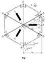
- FIG. 3 a diagram of the stator flooding space pointer I for section-wise switching between 3 adjacent pointer positions
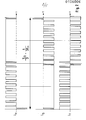
- FIG. 4 the The associated time profiles of the converter output currents i R , i S , i T
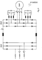
- FIG. 5 shows a basic circuit diagram of a 6-pulse intermediate circuit converter with a machine converter in phase sequence connection.
- i R i R (t)
- i S i S (t)
- Table 1 shows the relationship between the 6 possible switching positions of the converter and the associated discrete flow area pointer positions.
- Table 1 Discrete flow area pointers
- the switching functions for the currents i R , i S and i T recorded in columns 1, 2 and 3 in Table 1 can also be interpreted as distribution functions for the positive and the negative DC link current.
- the DC link current i d impressed by the mains converter (NSR) in accordance with FIG. 5 flows over the positive bridge half of the machine converter (MSR) and the winding R to the star point of the DAM and from there negatively back to the intermediate circuit via the phase winding S and the negative bridge half of the MSR.
- NSR mains converter
- the six discrete flow area indicators I 1 , ..., I 6 are - apart from the commutation period - only used.
- switch positions 1 to 6 are run through in ascending or descending sense without intermediate circuits, the flow indicator then jumps from one discrete position to the next in a counterclockwise or clockwise direction.
- Each step forward in the sense of circulation means an abrupt advance of the flow compared to the flow circulating at an approximately constant angular velocity and a subsequent, continuous, relative lag.
- the length of each flow space pointer expresses the amount of flow in the respective direction that is present during a 1/6 period.
- the size of the flow in each of the 6 discrete spatial directions is only dependent on the size of the intermediate circuit current i d in the case of basic oscillation clocking if one assumes approximately - as assumed above - an infinitely fast commutation.
- the flooding in the excellent spatial directions which are reduced in accordance with the relevant switch-on times, can be represented in the flooding pointer diagram as a shortened flooding pointer x i I i .
- the vectorial sum of the shortened flow pointers of a clock period T A then describes the path of the effective flow pointer whose length is always less than the length of one of the 6 discrete flow indicators in the fundamental mode:
- Fig. 1 now shows the diagram of the stator flow indicator with section-wise switching between 2 and more than 2 adjacent discrete flow indicator positions.
- the pointer tips of the 6 markedly shown flow indicators are connected in the form of a hexagon, which approximately describes the trajectory of the effective flow indicator when using the known two-strand pulse method.
- FIG. 3 One embodiment of the invention is shown in the flow area pointer diagram of FIG. 3. With constant pulsing between 3 selected adjacent pointer positions, the resulting flow space pointer traverses trajectory curves which may lie within the hatched area.
- the flow indicator can also describe a circular path (dashed). As mentioned above, this is associated with a complete suppression of all low-frequency pendulum moments.
- the boundary lines of the hatched area are two hexagons of different sizes offset by 30 °, which are specified by the minimum commutation times.
- the resulting flow indicator lies in a ⁇ 30 ° environment of a discrete flow indicator, then a switch is made between it and the two neighboring ones, one leading and one trailing.
- the selected points X and Y are in the vicinity of the discrete area pointer I 2 , which is why switching between the pointers I 1 , I 2 and I 3 .
- the related switching time y 1 is minimal.
- the limit given by the outer hexagon is thus determined by the minimum switch-on times of the leading and trailing pointer (I 1 and I 3 ), the inner limit lines are given by the minimum switch-on time of the area pointer (I 2 ).
Landscapes
- Engineering & Computer Science (AREA)
- Power Engineering (AREA)
- Control Of Ac Motors In General (AREA)
- Ultra Sonic Daignosis Equipment (AREA)
Priority Applications (3)
| Application Number | Priority Date | Filing Date | Title |
|---|---|---|---|
| AT82890149T ATE55663T1 (de) | 1982-10-18 | 1982-10-18 | Verfahren zur vorgabe des staenderdurchflutungsvektors. |
| DE8282890149T DE3280229D1 (de) | 1982-10-18 | 1982-10-18 | Verfahren zur vorgabe des staenderdurchflutungsvektors. |
| EP82890149A EP0106006B1 (fr) | 1982-10-18 | 1982-10-18 | Procédé pour la prédétermination du vecteur courant statorique |
Applications Claiming Priority (1)
| Application Number | Priority Date | Filing Date | Title |
|---|---|---|---|
| EP82890149A EP0106006B1 (fr) | 1982-10-18 | 1982-10-18 | Procédé pour la prédétermination du vecteur courant statorique |
Publications (2)
| Publication Number | Publication Date |
|---|---|
| EP0106006A1 true EP0106006A1 (fr) | 1984-04-25 |
| EP0106006B1 EP0106006B1 (fr) | 1990-08-16 |
Family
ID=8190177
Family Applications (1)
| Application Number | Title | Priority Date | Filing Date |
|---|---|---|---|
| EP82890149A Expired - Lifetime EP0106006B1 (fr) | 1982-10-18 | 1982-10-18 | Procédé pour la prédétermination du vecteur courant statorique |
Country Status (3)
| Country | Link |
|---|---|
| EP (1) | EP0106006B1 (fr) |
| AT (1) | ATE55663T1 (fr) |
| DE (1) | DE3280229D1 (fr) |
Cited By (3)
| Publication number | Priority date | Publication date | Assignee | Title |
|---|---|---|---|---|
| EP0207408A1 (fr) * | 1985-07-03 | 1987-01-07 | Siemens Aktiengesellschaft | Procédé de commande de l'angle de phase du courant ou de la tension de sortie d'un onduleur et dispositif pour sa mise en oeuvre |
| US4688163A (en) * | 1986-07-01 | 1987-08-18 | Siemens Aktiengesellschaft | Method for controlling the phase angle of the output current or the output voltage of a frequency converter and apparatus for carrying out the method |
| EP0298290A1 (fr) * | 1987-07-07 | 1989-01-11 | BBC Brown Boveri AG | Méthode et appareil pour faire fonctionner un générateur à induction |
Citations (6)
| Publication number | Priority date | Publication date | Assignee | Title |
|---|---|---|---|---|
| AT323847B (de) | 1972-07-26 | 1975-07-25 | Siemens Ag | Drehvektor-steueranordnung für die phasenlage des ständerstromvektors bei einer über einen mehrsphasigen umrichter gespeisten drehfeldmaschine |
| DE2552602A1 (de) * | 1975-11-24 | 1977-06-02 | Michael Dr Ing Blumenthal | Verfahren zur pulswinkelmodulation des staenderstromvektors von drehfeldmaschinen |
| US4028600A (en) * | 1973-08-23 | 1977-06-07 | Siemens Aktiengesellschaft | Method and apparatus for slow speed operation of an inverter controlled rotating field machine |
| AT341046B (de) | 1975-04-03 | 1978-01-10 | Siemens Ag | Drehvektor-steueranordnung fur die phasenlage des standerstromvektors bei einer uber einen mehrphasigen umrichter gespeisten drehfeldmaschine |
| DE2704533A1 (de) | 1977-02-03 | 1978-08-10 | Siemens Ag | Einrichtung zur steuerung der lage des staenderstromvektors einer ueber einen wechselrichter mit eingepraegtem strom gespeisten drehfeldmaschine |
| DE2756952A1 (de) | 1977-12-21 | 1979-06-28 | Bbc Brown Boveri & Cie | Steuersatz fuer einen selbstgefuehrten stromrichter |
-
1982
- 1982-10-18 AT AT82890149T patent/ATE55663T1/de not_active IP Right Cessation
- 1982-10-18 EP EP82890149A patent/EP0106006B1/fr not_active Expired - Lifetime
- 1982-10-18 DE DE8282890149T patent/DE3280229D1/de not_active Expired - Lifetime
Patent Citations (6)
| Publication number | Priority date | Publication date | Assignee | Title |
|---|---|---|---|---|
| AT323847B (de) | 1972-07-26 | 1975-07-25 | Siemens Ag | Drehvektor-steueranordnung für die phasenlage des ständerstromvektors bei einer über einen mehrsphasigen umrichter gespeisten drehfeldmaschine |
| US4028600A (en) * | 1973-08-23 | 1977-06-07 | Siemens Aktiengesellschaft | Method and apparatus for slow speed operation of an inverter controlled rotating field machine |
| AT341046B (de) | 1975-04-03 | 1978-01-10 | Siemens Ag | Drehvektor-steueranordnung fur die phasenlage des standerstromvektors bei einer uber einen mehrphasigen umrichter gespeisten drehfeldmaschine |
| DE2552602A1 (de) * | 1975-11-24 | 1977-06-02 | Michael Dr Ing Blumenthal | Verfahren zur pulswinkelmodulation des staenderstromvektors von drehfeldmaschinen |
| DE2704533A1 (de) | 1977-02-03 | 1978-08-10 | Siemens Ag | Einrichtung zur steuerung der lage des staenderstromvektors einer ueber einen wechselrichter mit eingepraegtem strom gespeisten drehfeldmaschine |
| DE2756952A1 (de) | 1977-12-21 | 1979-06-28 | Bbc Brown Boveri & Cie | Steuersatz fuer einen selbstgefuehrten stromrichter |
Cited By (3)
| Publication number | Priority date | Publication date | Assignee | Title |
|---|---|---|---|---|
| EP0207408A1 (fr) * | 1985-07-03 | 1987-01-07 | Siemens Aktiengesellschaft | Procédé de commande de l'angle de phase du courant ou de la tension de sortie d'un onduleur et dispositif pour sa mise en oeuvre |
| US4688163A (en) * | 1986-07-01 | 1987-08-18 | Siemens Aktiengesellschaft | Method for controlling the phase angle of the output current or the output voltage of a frequency converter and apparatus for carrying out the method |
| EP0298290A1 (fr) * | 1987-07-07 | 1989-01-11 | BBC Brown Boveri AG | Méthode et appareil pour faire fonctionner un générateur à induction |
Also Published As
| Publication number | Publication date |
|---|---|
| DE3280229D1 (de) | 1990-09-20 |
| EP0106006B1 (fr) | 1990-08-16 |
| ATE55663T1 (de) | 1990-09-15 |
Similar Documents
| Publication | Publication Date | Title |
|---|---|---|
| DE3779430T2 (de) | Steuerverfahren fuer impulsbreitenmodulationswechselrichter. | |
| DE3438504C2 (fr) | ||
| DE1488096B2 (de) | Wechselrichterschaltung | |
| DE3131344C2 (fr) | ||
| DE3101102C2 (fr) | ||
| DE2459986C2 (de) | Umformer | |
| DE2948946C2 (fr) | ||
| DE3012330A1 (de) | Impulsbreitenmodulierter wechselrichter und betriebsverfahren | |
| DE2605185C3 (de) | Einphasen-Stromrichter | |
| DE3131361C2 (fr) | ||
| DE3525413A1 (de) | Elektromagnetischer stroemungsmesser | |
| DE2236763C3 (de) | Verfahren und Anordnung zur Steuerung der Lage des Ständerstromvektors einer über einen Umrichter mit eingeprägtem Zwischenkreisstrom gespeisten Drehfeldmaschine | |
| EP0106006B1 (fr) | Procédé pour la prédétermination du vecteur courant statorique | |
| DE3119161A1 (de) | Selbstgetaktete vollbrueckenschaltung als vierquadrantensteller fuer elektromotore | |
| DE2313328C3 (de) | Steuerschaltung für einen Wechselrichter | |
| DE4241647C1 (de) | Verfahren der Vektormodulation für die Ansteuerung eines Pulswechselrichters | |
| DE2151019C3 (de) | Verfahren zur Regelung des einem Wechselstromnetz entnommenen oder zugeführten Stromes und Anordnung zur Durchführung des Verfahrens | |
| EP0198204A2 (fr) | Procédé et dispositif pour convertir du courant continu en courant alternatif | |
| DE2705343C2 (de) | Steuerverfahren für einen selbstgeführten, pulsgesteuerten Wechselrichter und Steueranordnung zur Bildung der Sollwerte für die Pulssteuerung | |
| DE3012329A1 (de) | Stromrichteranordnung | |
| DE3231945C2 (fr) | ||
| DE2945145C2 (fr) | ||
| EP3301805A1 (fr) | Procédé destiné au fonctionnement d'un onduleur et onduleur | |
| AT142092B (de) | Umrichter. | |
| DE3542753C2 (fr) |
Legal Events
| Date | Code | Title | Description |
|---|---|---|---|
| PUAI | Public reference made under article 153(3) epc to a published international application that has entered the european phase |
Free format text: ORIGINAL CODE: 0009012 |
|
| AK | Designated contracting states |
Designated state(s): AT CH DE IT LI SE |
|
| RBV | Designated contracting states (corrected) |
Designated state(s): AT CH DE IT LI SE |
|
| 17P | Request for examination filed |
Effective date: 19841015 |
|
| ITF | It: translation for a ep patent filed | ||
| GRAA | (expected) grant |
Free format text: ORIGINAL CODE: 0009210 |
|
| AK | Designated contracting states |
Kind code of ref document: B1 Designated state(s): AT CH DE IT LI SE |
|
| REF | Corresponds to: |
Ref document number: 55663 Country of ref document: AT Date of ref document: 19900915 Kind code of ref document: T |
|
| REF | Corresponds to: |
Ref document number: 3280229 Country of ref document: DE Date of ref document: 19900920 |
|
| PLBE | No opposition filed within time limit |
Free format text: ORIGINAL CODE: 0009261 |
|
| STAA | Information on the status of an ep patent application or granted ep patent |
Free format text: STATUS: NO OPPOSITION FILED WITHIN TIME LIMIT |
|
| 26N | No opposition filed | ||
| PGFP | Annual fee paid to national office [announced via postgrant information from national office to epo] |
Ref country code: CH Payment date: 19920928 Year of fee payment: 11 |
|
| PGFP | Annual fee paid to national office [announced via postgrant information from national office to epo] |
Ref country code: SE Payment date: 19920930 Year of fee payment: 11 |
|
| ITTA | It: last paid annual fee | ||
| PG25 | Lapsed in a contracting state [announced via postgrant information from national office to epo] |
Ref country code: SE Effective date: 19931019 |
|
| PG25 | Lapsed in a contracting state [announced via postgrant information from national office to epo] |
Ref country code: LI Effective date: 19931031 Ref country code: CH Effective date: 19931031 |
|
| PGFP | Annual fee paid to national office [announced via postgrant information from national office to epo] |
Ref country code: DE Payment date: 19931216 Year of fee payment: 12 |
|
| REG | Reference to a national code |
Ref country code: CH Ref legal event code: PL |
|
| EUG | Se: european patent has lapsed |
Ref document number: 82890149.6 Effective date: 19940510 |
|
| PG25 | Lapsed in a contracting state [announced via postgrant information from national office to epo] |
Ref country code: DE Effective date: 19950701 |
|
| PGFP | Annual fee paid to national office [announced via postgrant information from national office to epo] |
Ref country code: AT Payment date: 19951010 Year of fee payment: 14 |
|
| PG25 | Lapsed in a contracting state [announced via postgrant information from national office to epo] |
Ref country code: AT Effective date: 19961018 |
|
| APAH | Appeal reference modified |
Free format text: ORIGINAL CODE: EPIDOSCREFNO |