EP0207678B1 - Combination d'un dispositif pour le contrôle des tensions et une brosse à dents électrique - Google Patents
Combination d'un dispositif pour le contrôle des tensions et une brosse à dents électrique Download PDFInfo
- Publication number
- EP0207678B1 EP0207678B1 EP86304636A EP86304636A EP0207678B1 EP 0207678 B1 EP0207678 B1 EP 0207678B1 EP 86304636 A EP86304636 A EP 86304636A EP 86304636 A EP86304636 A EP 86304636A EP 0207678 B1 EP0207678 B1 EP 0207678B1
- Authority
- EP
- European Patent Office
- Prior art keywords
- battery
- recess
- light emitter
- brush
- conductors
- Prior art date
- Legal status (The legal status is an assumption and is not a legal conclusion. Google has not performed a legal analysis and makes no representation as to the accuracy of the status listed.)
- Expired - Lifetime
Links
- 239000004020 conductor Substances 0.000 claims description 30
- 230000001419 dependent effect Effects 0.000 claims description 2
- 238000005259 measurement Methods 0.000 description 3
- 210000000214 mouth Anatomy 0.000 description 2
- 210000003296 saliva Anatomy 0.000 description 2
- KRHYYFGTRYWZRS-UHFFFAOYSA-M Fluoride anion Chemical compound [F-] KRHYYFGTRYWZRS-UHFFFAOYSA-M 0.000 description 1
- 230000004913 activation Effects 0.000 description 1
- 230000000903 blocking effect Effects 0.000 description 1
- 230000001680 brushing effect Effects 0.000 description 1
- 208000002925 dental caries Diseases 0.000 description 1
- 229910052731 fluorine Inorganic materials 0.000 description 1
- 239000011737 fluorine Substances 0.000 description 1
- -1 fluorine ions Chemical class 0.000 description 1
- 230000002779 inactivation Effects 0.000 description 1
- 201000001245 periodontitis Diseases 0.000 description 1
- 230000002093 peripheral effect Effects 0.000 description 1
- 230000002265 prevention Effects 0.000 description 1
- 239000000523 sample Substances 0.000 description 1
- 229940034610 toothpaste Drugs 0.000 description 1
- 239000000606 toothpaste Substances 0.000 description 1
Images


Classifications
-
- G—PHYSICS
- G01—MEASURING; TESTING
- G01R—MEASURING ELECTRIC VARIABLES; MEASURING MAGNETIC VARIABLES
- G01R19/00—Arrangements for measuring currents or voltages or for indicating presence or sign thereof
-
- G—PHYSICS
- G01—MEASURING; TESTING
- G01R—MEASURING ELECTRIC VARIABLES; MEASURING MAGNETIC VARIABLES
- G01R19/00—Arrangements for measuring currents or voltages or for indicating presence or sign thereof
- G01R19/145—Indicating the presence of current or voltage
- G01R19/155—Indicating the presence of voltage
Definitions
- This invention relates to a combination of an electric tooth-brush and a voltage testing device for the tooth-brush.
- Electric tooth-brushes are known in which a battery housed in the handle is arranged so that in use a current is passed through the body of the user between the mouth and the hand holding the brush.
- GB-A- 390 985 One such tooth-brush is described in GB-A- 390 985, in which the bristles are formed of the usual non-conducting material and one or more wires leading from the battery is or are arranged between the folds of the bristles, so that when the bristles are moistened in use a current passes from the battery through the brush to a conducting hand grip.
- An indicator lamp adapted to be contacted with the battery terminals may be mounted at the end of the handle to show whether the battery is in order.
- a battery testing device in which an insulating body holds an indicator lamp connected to two probes that are adapted to be contacted with the battery terminals.
- the present invention provides an improved combination of an electric tooth-brush with a separate battery testing device.
- an electric tooth-brush containing a battery comprising: an elongate handle having a grip portion at one end thereof and a head portion studded with bristles at the other end thereof, said battery being disposed in said grip portion; an electrically conductive member mounted on the exterior of said grip portion and electrically connected to one pole of said battery; and an electrically conductive bar disposed in said handle and extending lengthwise thereof from said battery to adjacent said bristles, one end of said bar being electrically connected to the other pole of said battery and a portion of said bar being exposed to the exterior of said head portion via at least one slot in said head portion, said voltage testing device comprising: an elongate device body positionable adjacent said tooth-brush and extendable lengthwise thereof between said electrically conductive member and said exposed portion of said bar; a light emitter mounted inside said body and visible from outside said body; a pair of electrical conductors carried by said body and
- an electric tooth-brush 21 has an elongate handle 22 having a grip portion 23 in which a battery 24 is accommodated.
- An electrically conductive bar 25 is embedded in the handle 22, having one end in contact with a negative pole of the battery 24 and the other end reaching brush bristles 26, with which a head portion of the tooth-brush is studded.
- Adjacent the brush bristles 26, slots 27 and 28 are formed in top and bottom surfaces of the handle 22, respectively.
- An electrically conductive cover plate 29 wrapping the grip portion 23 is in contact with a positive pole of the battery 24.
- a collar 30 is provided for blocking saliva flowing out of the brush bristles which would otherwise reach fingers grasping the grip portion.
- the positive pole of the battery 24 electrically conducts to the user's hand through the cover plate 29 and the negative pole to the oral cavity through the electrically conductive bar 25 and saliva in the slot 28, thereby establishing a closed circuit.
- this closed circuit causes electrical permeation of fluorine ions into the teeth, thereby ensuring protection and prevention against tooth decay and pyorrhea.
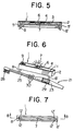
- a voltage testing device for use in a first embodiment of this invention has an elongate device body 1 which comprises a casing 2 formed, in its top surface, with a recess 3 and a cover 4 placed to cover the recess 3. Near axially opposite ends of the recess, holes 5 and 5' are formed in the bottom wall of the casing and an opening 6 is formed in the cover 4 substantially in the middle thereof.
- a light emitter 7 such as a light emitting diode is supported so as to underlie the opening 6 within the recess 3.
- opposite leads of the light emitter 7 are connected with electrical wire conductors 8 and 8' which extend through the holes 5 and 5' to project outwardly of the casing 2, terminating in projections which are bent about 45 o longitudinally outwardly for fixing the electrical conductors 8 and 8'.
- the electrical conductors 8 and 8' are respectively brought into electrical connection to the negative and positive poles of the battery 24 of the tooth-brush 21, in a manner to be described later.
- Markings including an arrow 9 and a picture 10 of a tooth-brush, are provided on the top surface of the cover 4, and opposite side surfaces of the casing 2 are corrugated at 11 near the electrical conductor 8'.
- the voltage testing device constructed as above is applied to the electrical tooth-brush 21 in order to measure the voltage of the battery 24 incorporated therein. More particularly, for measurement of the voltage, the testing device body 1 is carried by hand and the electrical conductor 8 is inserted into the slot 27 in the tooth-brush 21 so as to be brought into engagement with the electrically conductive bar 25 while the electrical conductor 8' is brought into engagement with the cover plate 29 of the tooth-brush 21. Then, if the voltage of the battery 24 is still above a predetermined level, the light emitter 7 will be lit but if not so, it remains unlit, thus making it possible to discern validity or invalidity of the battery 24.
- the arrow 9 and picture 10 as well as corrugations 11 aid the use to correctly put the electrical conductors 8 and 8' into electrical connection with the intended poles, that is, the negative and positive poles, respectively.
- the electrical wire conductor 8 can rest, in a so-called automatic fashion, on the electrically conductive bar 25 in contact with the negative pole and the opposite electrical wire conductor 8' can similarly rest on the cover plate 29 in contact with the positive pole.
- the user may be experienced in knowing that the corrugations 11 are provided on the side of the electrical conductor 8', so that the same posture as above can also be obtained in a so-called automatic fashion by simply putting into engagement with the cover plate 29 the electrical conductor 8' near the corrugations 11 felt by the fingers without asking the user to pay attention to the arrow 9 and picture 10.
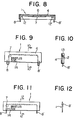
- FIGs. 7 and 8 there is shown a device for use in a second embodiment, which is identical to the first embodiment, with the exception that the casing 2 of the first embodiment is eliminated and instead the peripheral edge of a cover 4 is elongate downwardly, and that electrical conductors 8 and 8' are carried on a pair of opposing fixtures 12 and 12' depending from the back of the top surface of the cover 4.
- the testing device of the second embodiment may be used in quite the same way as that of the first embodiment.
- a testing device for use in a third embodiment as shown in Figs. 9 and 10, a light emitter 7 and electrical wire conductors 8 and 8' are received in a recess 13 provided in a casing block 2 and a transparent cover 4 is placed to cover the casing 2. Markings 14 in the form of characters reading "BRISTLES SIDE" are provided on the cover 4.
- the testing device of the third embodiment may be used in quite the same way as the first embodiment.
- a device body 1 is formed of two cards which are bonded together after a light emitter 7 and electrical conductors 8 and 8' have been sandwiched therebetween.
- markings 14 a symbol (-) is applied in addition to the same characters as those of the third embodiment.
- the electrical conductors 8 and 8' of this embodiment may be of printed wiring.
- a fifth embodiment of this invention has a testing device which resembles that of the fourth embodiment but a light emitter 7 of the fifth embodiment is exposed to the outside through an opening 15 formed in a device body 1, so that activation or inactivation of the light emitter 7 can visually be observed more clearly.
- Used as markings are symbols (-) and (+) and an arrow. This embodiment may also be used in quite the same manner as the first embodiment.
- a sixth embodiment of this invention has a testing device with a body 1 including a casing 2 formed, in its bottom surface, with a recess 3 and a bottom plate 16 snugly fitted, preferably snapped, in the recess 3.
- Electrical conductors 8 and 8' extend to the outside through holes 17 and 17' formed in opposite side walls of the casing 2, and a light emitter 7 can visually be observed through either an opening 18 in the casing 2 or an opening 19 in the bottom plate 16.
- the sixth embodiment may be operated in quite the same way as the first embodiment.
Landscapes
- Physics & Mathematics (AREA)
- General Physics & Mathematics (AREA)
- Measurement Of Current Or Voltage (AREA)
- Brushes (AREA)
- Measuring Instrument Details And Bridges, And Automatic Balancing Devices (AREA)
- Secondary Cells (AREA)
Claims (10)
- Combinaison d'une :
brosse à dents électrique (21) contenant une batterie (24) ; et d'un
dispositif pour le contrôle des tensions permettant de contrôler l'état de la batterie, la brosse à dents comprenant :
un manche allongé (22) présentant à l'une de ses extrémités une partie pour la prise (23) et à l'autre de ses extrémités une tête garnie de poils (26), la batterie étant placée dans la partie de prise ;
un organe électriquement conducteur (29) monté à l'extérieur de la partie de prise et relié électriquement à un pôle de la batterie ; et
une barre électriquement conductrice (25) placée dans le manche et s'étendant le long de celui-ci depuis la batterie jusqu'à proximité des poils, une des extrémités de la barre étant reliée électriquement à l'autre pôle de la batterie et une partie de la barre étant exposée à l'extérieur de la tête au moyen d'au moins une fente ménagée (27,28) dans la tête, le dispositif de contrôle des tensions comprenant :
un corps (1) allongé pouvant être placé en position adjacente à la brosse à dents et s'étendant tout au long de celle-ci entre l'organe électriquement conducteur et la partie exposée de la barre ;
un émetteur de lumière (7) monté à l'intérieur du corps et visible depuis l'extérieur ;
une paire de conducteurs électriques (8,8') portée par le corps et s'éloignant en direction opposée depuis l'émetteur de lumière, ces conducteurs présentant des extrémités extérieures exposées, espacées longitudinalement, se prolongeant vers l'extérieur depuis le corps à proximité de ses extrémités opposées et placés à des emplacements correspondant aux emplacements de l'organe électriquement conducteur et de la partie exposée de la barre, de façon à ce que les extrémités extérieures puissent simultanément être en contact avec l'organe électriquement conducteur et la partie exposée de la barre, ces conducteurs présentant des extrémités intérieures reliées à l'émetteur de lumière ; et
des moyens d'indication (9,10,11 ; ou 14) sur le corps pour indiquer la direction selon laquelle le corps doit être placé par rapport à la brosse à dents afin de contrôler la batterie, de telle façon que les extrémités extérieures des conducteurs soient en contact avec l'organe électriquement conducteur et avec la partie exposée de la barre, l'émission de lumière par l'émetteur de lumière étant dépendante des conditions de la batterie. - Combinaison selon la revendication 1, dans laquelle les moyens d'indication comprennent un marquage indiquant à quel pôle au moins l'un des conducteurs électriques (8,8') doit être relié.
- Combinaison selon la revendication 1 ou 2, dans laquelle les moyens d'indication comprennent des caractères (14).
- Combinaison selon la revendication 3, dans laquelle les caractères (14) identifient une partie de la brosse à dents.
- Combinaison selon l'une des revendications précédentes, dans laquelle les moyens d'indication comprennent une image (10).
- Combinaison selon l'une des revendications précédentes, dans laquelle l'émetteur de lumière (7) est placé face à l'ouverture (6) ménagée dans le corps (1).
- Combinaison selon l'une des revendications précédentes, dans laquelle le corps (1) comprend deux organes (2,4) qui y sont fixés, le deuxième organe présentant une cavité interne (3) dans laquelle sont logés l'émetteur de lumière (7) et les deux conducteurs électriques (8,8').
- Combinaison selon la revendication 7, dans laquelle le corps (1) a une forme de boite.
- Combinaison selon la revendication 7, dans laquelle le corps (1) est sensiblement rectangulaire et comprend une enveloppe (2) présentant un évidement allongé (3) qui est ouvert sur son côté supérieur et un couvercle (4) couvrant le côté supérieur de l'évidement, ce couvercle présentant une ouverture (6) traversante située longitudinalement sensiblement vers le milieu, cette enveloppe présentant deux perçages (5,5') placés à proximité des extrémités longitudinales opposées de l'enveloppe et s'étendant depuis l'évidement à travers le fond de l'enveloppe, l'émetteur de lumière (7) étant placé dans l'évidement en dessous de l'ouverture, les conducteurs (8,8') étant placés dans l'évidement et étant courbés pour s'éloigner en divergeant depuis le corps, et les moyens d'indication (9,10,11) étant placés sur le couvercle.
- Combinaison selon l'une des revendications 1 à 6, dans laquelle le corps (1) est sensiblement rectangulaire et comprend un couvercle (4) présentant une paroi principale et des parois de côté et d'extrémité s'étendant vers le bas depuis la paroi principale et définissant un évidement allongé qui est ouvert au fond, la paroi principale présentant une ouverture (6) traversante longitudinalement sensiblement vers le milieu, l'émetteur de lumière (7) étant placé dans l'évidement sous l'ouverture, les conducteurs (8,8') étant placés dans l'évidement et présentant leurs extrémités extérieures traversant le fond ouvert de l'évidement, le couvercle présentant des fixations (12,12') pour retenir les conducteurs dans l'évidement, et les moyens d'indication (9,10,11) étant placés sur le couvercle.
Applications Claiming Priority (4)
| Application Number | Priority Date | Filing Date | Title |
|---|---|---|---|
| JP131454/85 | 1985-06-17 | ||
| JP60131454A JPS61288810A (ja) | 1985-06-17 | 1985-06-17 | 電子歯ブラシの電圧検知法 |
| JP204892/85 | 1985-09-17 | ||
| JP60204892A JPH0627792B2 (ja) | 1985-09-17 | 1985-09-17 | 電子歯ブラシの電圧テスタ− |
Publications (2)
| Publication Number | Publication Date |
|---|---|
| EP0207678A1 EP0207678A1 (fr) | 1987-01-07 |
| EP0207678B1 true EP0207678B1 (fr) | 1992-01-02 |
Family
ID=26466292
Family Applications (1)
| Application Number | Title | Priority Date | Filing Date |
|---|---|---|---|
| EP86304636A Expired - Lifetime EP0207678B1 (fr) | 1985-06-17 | 1986-06-16 | Combination d'un dispositif pour le contrôle des tensions et une brosse à dents électrique |
Country Status (7)
| Country | Link |
|---|---|
| US (1) | US5003250A (fr) |
| EP (1) | EP0207678B1 (fr) |
| KR (1) | KR950004619B1 (fr) |
| AU (1) | AU593258B2 (fr) |
| DE (1) | DE3683199D1 (fr) |
| HK (1) | HK67792A (fr) |
| SG (1) | SG71792G (fr) |
Families Citing this family (6)
| Publication number | Priority date | Publication date | Assignee | Title |
|---|---|---|---|---|
| US4825874A (en) * | 1986-10-17 | 1989-05-02 | Uhlemann Hans J | Cardiac diagnosis instrument |
| JP2592791B2 (ja) * | 1989-01-31 | 1997-03-19 | 株式会社サンギ | 電子歯ブラシ |
| EP0417963B1 (fr) * | 1989-09-12 | 1994-08-03 | Hiroshi Hukuba | Brosse à dents avec vérificateur de tension |
| TW267946B (fr) * | 1994-05-02 | 1996-01-11 | Hukuba Hiroshi | |
| US8193771B2 (en) * | 2008-05-22 | 2012-06-05 | Nuwave Technologies, Inc. | Battery tester |
| US11382413B2 (en) * | 2016-10-19 | 2022-07-12 | Colgate-Palmolive Company | Oral care implement |
Citations (2)
| Publication number | Priority date | Publication date | Assignee | Title |
|---|---|---|---|---|
| GB390985A (en) * | 1931-08-17 | 1933-04-20 | Edward Jones | Improvements in electric brushes |
| EP0174740A1 (fr) * | 1984-08-14 | 1986-03-19 | Hiroshi Hukuba | Brosse à dents électrique |
Family Cites Families (13)
| Publication number | Priority date | Publication date | Assignee | Title |
|---|---|---|---|---|
| US3667454A (en) * | 1970-06-12 | 1972-06-06 | Larry W Prince | Toothbrush with ultraviolet emitter |
| US3657648A (en) * | 1971-02-08 | 1972-04-18 | Wire Sales Co | Electrical testing device |
| US3753095A (en) * | 1971-02-16 | 1973-08-14 | N Nichols | Battery tester having a pliable resilient body member for accomodating the battery to be tested |
| US4025850A (en) * | 1975-10-01 | 1977-05-24 | Joseph Spiteri | Passive, solid state wide range voltage checker |
| US4439736A (en) * | 1981-05-13 | 1984-03-27 | Cable Electric Products, Inc. | Battery testing system |
| GB2124787B (en) * | 1982-08-06 | 1984-10-03 | George G Collins | Battery and fuse testers |
| US4514695A (en) * | 1982-09-03 | 1985-04-30 | Lau Chester P K | Pocket battery tester |
| CH674266A5 (fr) * | 1982-10-05 | 1990-05-15 | Walter Eberhart | |
| US4533864A (en) * | 1983-04-21 | 1985-08-06 | Northern Telecom Limited | Test instrument with flexibly connected head |
| US4564802A (en) * | 1983-07-15 | 1986-01-14 | Collins George G | Test device for fuses and batteries |
| AU585846B2 (en) * | 1985-01-24 | 1989-06-29 | Maurice Glover | Electrical parameter test unit |
| JPH0925815A (ja) * | 1995-06-07 | 1997-01-28 | Caterpillar Inc | 後噴射燃焼排気ガス清浄化システム及びその方法 |
| JPH0925816A (ja) * | 1995-07-11 | 1997-01-28 | Nissan Motor Co Ltd | エンジンの排気浄化装置 |
-
1986
- 1986-06-16 DE DE8686304636T patent/DE3683199D1/de not_active Expired - Lifetime
- 1986-06-16 EP EP86304636A patent/EP0207678B1/fr not_active Expired - Lifetime
- 1986-06-16 AU AU58879/86A patent/AU593258B2/en not_active Ceased
- 1986-06-16 KR KR1019860004777A patent/KR950004619B1/ko not_active Expired - Fee Related
-
1988
- 1988-08-09 US US07/230,318 patent/US5003250A/en not_active Expired - Fee Related
-
1992
- 1992-07-10 SG SG717/92A patent/SG71792G/en unknown
- 1992-09-10 HK HK677/92A patent/HK67792A/en not_active IP Right Cessation
Patent Citations (2)
| Publication number | Priority date | Publication date | Assignee | Title |
|---|---|---|---|---|
| GB390985A (en) * | 1931-08-17 | 1933-04-20 | Edward Jones | Improvements in electric brushes |
| EP0174740A1 (fr) * | 1984-08-14 | 1986-03-19 | Hiroshi Hukuba | Brosse à dents électrique |
Also Published As
| Publication number | Publication date |
|---|---|
| SG71792G (en) | 1992-10-02 |
| AU5887986A (en) | 1986-12-24 |
| DE3683199D1 (de) | 1992-02-13 |
| US5003250A (en) | 1991-03-26 |
| KR870000593A (ko) | 1987-02-19 |
| AU593258B2 (en) | 1990-02-08 |
| EP0207678A1 (fr) | 1987-01-07 |
| KR950004619B1 (ko) | 1995-05-03 |
| HK67792A (en) | 1992-09-18 |
Similar Documents
| Publication | Publication Date | Title |
|---|---|---|
| US5133102A (en) | Electronic toothbrush | |
| JP2613667B2 (ja) | 電圧テスター付きイオン歯ブラシ | |
| EP0660680B1 (fr) | Manche sensible a la force pour ustensile a main | |
| HK67792A (en) | Combination of a voltage testing device and an electric tooth brush | |
| DE60043637D1 (de) | Elektrischer Verbinder mit Haltemitteln zur lösbaren Fixierung einer Bauelementenpackung | |
| DE69800154D1 (de) | Elektrische Anschlussvorrichtung mit verbesserter Kontaktsicherheit | |
| ATE195203T1 (de) | Elektrische anschlussklemmeinrichtung | |
| ZA859612B (en) | A monopolar or bipolar electrochemical terminal unit having an electric current transmission element | |
| KR900007153A (ko) | 발전동기의 전기적 접속물을 제조하는 장치 | |
| DE69314757D1 (de) | Gehäuse für elektrische Verbinder mit verbesserter Kontakteinführung | |
| US3725780A (en) | Portable miniature bulb tester having bristle brushes for contacting the bulb terminals | |
| US285977A (en) | Elected medical | |
| HK36091A (en) | Electric motors and their assembly | |
| US3525919A (en) | Terminal structure for a battery-powered appliance | |
| HUP0103791A2 (en) | Electric appliance switch comprising a fuse seat | |
| JPH10243820A (ja) | イオン歯間ブラシ | |
| CA2008640C (fr) | Brosse a dents electronique | |
| JPH0627792B2 (ja) | 電子歯ブラシの電圧テスタ− | |
| ATE303005T1 (de) | Elektrische verbindungs- oder anschlussklemme | |
| US3657648A (en) | Electrical testing device | |
| EP0284909A3 (en) | Sensor for measuring the current or the voltage of electric conductive layers on a reference chip | |
| JPH07313253A (ja) | 電子歯ブラシの電圧検知装置 | |
| JPS6230292Y2 (fr) | ||
| JPS6310144Y2 (fr) | ||
| KR850003006Y1 (ko) | 100v-220v겸용기기의 전압절환장치 |
Legal Events
| Date | Code | Title | Description |
|---|---|---|---|
| PUAI | Public reference made under article 153(3) epc to a published international application that has entered the european phase |
Free format text: ORIGINAL CODE: 0009012 |
|
| AK | Designated contracting states |
Kind code of ref document: A1 Designated state(s): CH DE FR GB IT LI |
|
| 17P | Request for examination filed |
Effective date: 19870213 |
|
| 17Q | First examination report despatched |
Effective date: 19890421 |
|
| GRAA | (expected) grant |
Free format text: ORIGINAL CODE: 0009210 |
|
| AK | Designated contracting states |
Kind code of ref document: B1 Designated state(s): CH DE FR GB IT LI |
|
| REF | Corresponds to: |
Ref document number: 3683199 Country of ref document: DE Date of ref document: 19920213 |
|
| ITF | It: translation for a ep patent filed | ||
| ET | Fr: translation filed | ||
| PLBE | No opposition filed within time limit |
Free format text: ORIGINAL CODE: 0009261 |
|
| STAA | Information on the status of an ep patent application or granted ep patent |
Free format text: STATUS: NO OPPOSITION FILED WITHIN TIME LIMIT |
|
| 26N | No opposition filed | ||
| PGFP | Annual fee paid to national office [announced via postgrant information from national office to epo] |
Ref country code: GB Payment date: 19980603 Year of fee payment: 13 |
|
| PGFP | Annual fee paid to national office [announced via postgrant information from national office to epo] |
Ref country code: FR Payment date: 19980619 Year of fee payment: 13 |
|
| PGFP | Annual fee paid to national office [announced via postgrant information from national office to epo] |
Ref country code: CH Payment date: 19980626 Year of fee payment: 13 |
|
| PGFP | Annual fee paid to national office [announced via postgrant information from national office to epo] |
Ref country code: DE Payment date: 19980831 Year of fee payment: 13 |
|
| PG25 | Lapsed in a contracting state [announced via postgrant information from national office to epo] |
Ref country code: GB Free format text: LAPSE BECAUSE OF NON-PAYMENT OF DUE FEES Effective date: 19990616 |
|
| PG25 | Lapsed in a contracting state [announced via postgrant information from national office to epo] |
Ref country code: LI Free format text: LAPSE BECAUSE OF NON-PAYMENT OF DUE FEES Effective date: 19990630 Ref country code: FR Free format text: THE PATENT HAS BEEN ANNULLED BY A DECISION OF A NATIONAL AUTHORITY Effective date: 19990630 Ref country code: CH Free format text: LAPSE BECAUSE OF NON-PAYMENT OF DUE FEES Effective date: 19990630 |
|
| GBPC | Gb: european patent ceased through non-payment of renewal fee |
Effective date: 19990616 |
|
| REG | Reference to a national code |
Ref country code: CH Ref legal event code: PL |
|
| PG25 | Lapsed in a contracting state [announced via postgrant information from national office to epo] |
Ref country code: DE Free format text: LAPSE BECAUSE OF NON-PAYMENT OF DUE FEES Effective date: 20000503 |
|
| REG | Reference to a national code |
Ref country code: FR Ref legal event code: ST |
|
| PG25 | Lapsed in a contracting state [announced via postgrant information from national office to epo] |
Ref country code: IT Free format text: LAPSE BECAUSE OF NON-PAYMENT OF DUE FEES;WARNING: LAPSES OF ITALIAN PATENTS WITH EFFECTIVE DATE BEFORE 2007 MAY HAVE OCCURRED AT ANY TIME BEFORE 2007. THE CORRECT EFFECTIVE DATE MAY BE DIFFERENT FROM THE ONE RECORDED. Effective date: 20050616 |