EP0207706A2 - Anordnung zum Anbieten von Blättern - Google Patents
Anordnung zum Anbieten von Blättern Download PDFInfo
- Publication number
- EP0207706A2 EP0207706A2 EP86304809A EP86304809A EP0207706A2 EP 0207706 A2 EP0207706 A2 EP 0207706A2 EP 86304809 A EP86304809 A EP 86304809A EP 86304809 A EP86304809 A EP 86304809A EP 0207706 A2 EP0207706 A2 EP 0207706A2
- Authority
- EP
- European Patent Office
- Prior art keywords
- stripping device
- stack
- sheets
- assembly according
- sheet
- Prior art date
- Legal status (The legal status is an assumption and is not a legal conclusion. Google has not performed a legal analysis and makes no representation as to the accuracy of the status listed.)
- Granted
Links
Images
Classifications
-
- B—PERFORMING OPERATIONS; TRANSPORTING
- B65—CONVEYING; PACKING; STORING; HANDLING THIN OR FILAMENTARY MATERIAL
- B65H—HANDLING THIN OR FILAMENTARY MATERIAL, e.g. SHEETS, WEBS, CABLES
- B65H29/00—Delivering or advancing articles from machines; Advancing articles to or into piles
- B65H29/38—Delivering or advancing articles from machines; Advancing articles to or into piles by movable piling or advancing arms, frames, plates, or like members with which the articles are maintained in face contact
- B65H29/40—Members rotated about an axis perpendicular to direction of article movement, e.g. star-wheels formed by S-shaped members
-
- G—PHYSICS
- G07—CHECKING-DEVICES
- G07D—HANDLING OF COINS OR VALUABLE PAPERS, e.g. TESTING, SORTING BY DENOMINATIONS, COUNTING, DISPENSING, CHANGING OR DEPOSITING
- G07D11/00—Devices accepting coins; Devices accepting, dispensing, sorting or counting valuable papers
- G07D11/10—Mechanical details
-
- B—PERFORMING OPERATIONS; TRANSPORTING
- B65—CONVEYING; PACKING; STORING; HANDLING THIN OR FILAMENTARY MATERIAL
- B65H—HANDLING THIN OR FILAMENTARY MATERIAL, e.g. SHEETS, WEBS, CABLES
- B65H2701/00—Handled material; Storage means
- B65H2701/10—Handled articles or webs
- B65H2701/19—Specific article or web
- B65H2701/1912—Banknotes, bills and cheques or the like
Definitions
- the invention relates to a sheet presenting assembly for presenting a stack of sheets to a present station.
- the invention has particular application to the dispensing of banknotes but may also be used with other document handling apparatus.
- a sheet presenting assembly comprises a rotatable sheet carrying device having a plurality of sheet receiving slots; a stripping device cooperating in a first position at a stripping station with the sheet carrying device to strip sheets from the sheet carrying device to form a stack of sheets, the stripping device being movable to a second position in which the stack of sheets is clamped between the stripping device and a movable surface; and drive means adapted to move the stripping device and the movable surface with a stack of sheets clamped therebetween to a present station.
- the invention simplifies known sheet presenting assemblies by utilising the stripping device not only to strip sheets from the sheet carrying device but also to clamp the stack of sheets while the stack is moved towards a present station (usually associated with a present outlet). This simplifies the construction of the device by reducing the number elements required thus increasing the reliability of the assembly.
- stack of sheets should be understood to include a single sheet.
- the stripping device is also movable in cooperation with the movable surface to convey the stack of sheets to a dump station.
- the dump station may be positioned above a dump container into which the stack of sheets falls under gravity.
- the stack may be transferred at the dump station to conveying means for conveying the stack to a dump container.
- Movement of the stripping device may be controlled in a number of ways.
- at least one portion of the stripping device comprises a cam follower cooperating with a respective cam of the assembly which is fixed relatively to the stripping device whereby movement of the cam follower along the cam in response to movement of the stripping device towards the present station causes the stripping device to move from the first to the second position.
- a dump station it is particularly convenient if the cam and cam follower cooperate during movement of the stripping device towards the dump station to cause the stripping device to release the stack.
- the movable surface may comprise at least one, preferably two, endless belts coupled to the stripping device and driven by the drive means. In the latter case the surface is defined in two spaced portions.
- the drive means may include two drive motors for separably driving the stripping device and movable surface.
- the drive means comprises a reversable motor coupled to the stripping device and movable surface.
- the movable surface is driven by the drive means and is coupled to the stripping device to cause movement of the stripping device. This ensures that both the stripping device and movable surface move at the same speed.
- the stripping device comprises at least one plate.
- the or each plate is pivotally mounted relative to the movable surface.
- the sheet carrying device may be provided by one or more stacking wheels of conventional form mounted on an axle and arranged to receive single sheets from a conventional sheet supplying device. Where a plurality of stacking wheels are provided, the sheet stripping device preferably comprises a plurality of plates which extend between adjacent pairs of stacking wheels when the stripping device is in its first position at the stripping station.
- the invention is particularly suited for use with banknote dispensing apparatus.
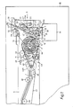
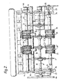
- the apparatus illustrated in Figure 1 forms part of a banknote dispenser of otherwise conventional form in which a selected quantity of banknotes are fed singly from a store (not shown) along a feed path l defined by endless belts 11, 11' to a set of four stacking wheels 2-5 ( Figure 2).
- the endless belts 11, 11' pass around idler pulleys 40 mounted between frame members 9.
- the belt 11' passes around a drive pulley non-rotatably mounted on a drive shaft 41.
- a drive pulley 42 is non-rotatably mounted to the shaft 41 externally of a frame member 9 and engages a drive pulley 43.
- the pulley 43 is driven by a motor (not shown) to cause the belts 11, 11' to carry banknotes along the path 1 to the stacking wheels 2-5.
- Each stacking wheel 2-5 comprises a set of curved tines 6 defining sheet receiving slots 7 therebetween.
- the stacking wheels 2-5 are mounted non-rotatably on a drive shaft 8 supported between the frame members 9.
- a drive pulley 44 is non-rotatably mounted on the shaft 8 and is driven by the drive motor by virtue of the contact between pulley 43 and a pulley 44A which is coupled with the pulley 44 by an endless belt.
- Single sheets fed along the feed path 1 will enter respective sheet receiving slots 7 and be carried in a clockwise direction as seen in Figure 1 by the stacking wheels 2-5 towards a stripping station 10.
- a portion 12 of the endless belt 11 extends over the stacking wheels 2-5.
- the periphery of the stacking wheels moves at a speed less than the speed of movement of the belt 11 and this has the effect of causing the belt 11 to nudge any protruding note back into the stacking wheel slot.
- a stripping device 13 comprising a plate having two sections 14, 15, extending between the stacking wheels 2, 3 and 4,5 respectively and end sections 17, 18.
- the sections 14, 15, 17, 18 are integrally connected at positions radially outwardly of the stacking wheels 2-5.
- the stripping device 13 is attached by tie clamps at two points (one of which 19 is shown in Figure 1) to respective toothed belts 20,20' in engagement with the smooth outer faces of the toothed belts 20, 20'.
- the belts 20, 20' are entraine.d around respective drive pulleys 21 non-rotatably mounted to a shaft 45 journaled between the frame members 9.
- a drive pulley 46 mounted on the shaft 45 is connected via a belt 47 to a reversable drive motor 22.
- the drive belts 20, 20' pass around respective tensioners 21' which are movable to adjust the tension of the belts.
- the belts 20, 20' also extend around idler rollers 26.
- the ends of the stripping device 13 remote from the stacking wheels 2-5 include a pair of cam followers 23.
- Each cam follower 23 includes a pin 24 which is received in a respective slot 25 defined by the frame members 9 and associated guide 16 and providing respective cam surfaces.
- the pins 24 are constrained to move within the slots 25 and control the position of the stripping device 13 relative to the belts 20, 20'.
- the slots have curved portions 25A and rectilinear portions 25B.
- sheets held in the sheet receiving slots 7 are stripped out of the slots by the stripping device 13 in its first position shown in solid lines in Figure 1 and stack against a set of four return plates 27 integrally formed with the device 13.
- the return plates 27 reregister the bottom edges of any untidily stacked notes.
- a microcomputer determines when the required number of sheets has been stacked and then controls the drive motor 22 to cause the pulleys 21 to rotate in a clockwise direction (as seen in Figure 1). This causes the pins 24 to move in a clockwise direction in the slots 25 thus causing the stripping device 13 to pivot in a clockwise direction to its second position 13' in which the stack of notes 28 is clamped against the belts 20, 20'. At the same time clockwise rotation of the pulleys 21 causes the belts 20, 20' to rotate and causes the stripping device 13 to move with the stack of notes 28 and the belts 20, 20' towards a present station 29 associated with an outlet 30.
- the stripping device 13 is shown in phantom at 13" with the clamped stack of notes 28 and part of the clamp 13" protruding through the present outlet 30. In this position, a user can withdraw the stack of notes. An adjacent sensor 32 senses this removal and, via the microcomputer actuates the drive motor 22 to cause the pulleys 21 to rotate in an anti-clockwise direction thus withdrawing the stripping device 13 from the present outlet 30 back to the stripping station 10. As the stripping device approaches this position, the pins 24 of the cam follower 23 will cause the stripping device 13 to rotate in an anti-clockwise direction back to the position shown in Figure 2 due to their movement within the portions 25A of the slots 25.
- the microcomputer determines that the number of sheets in the stack is incorrect, it causes the drive motor 22 to rotate the pulleys 21 initially in an anti-clockwise direction. This causes the stripping device 13 to rotate in an anti-clockwise direction to a dump station 33 where the position of the device 13 is indicated in phantom at 13"'. In this position, the stack of sheets drops into a dump container 34 of conventional form. Once the stack has been released, the drive motor 22 is driven in a clockwise direction and the stripping device 13 returns to the stripping station 10 in the position shown in solid lines in Figure 1.
- the dispensing apparatus will be positioned in a secure housing indicated schematically at 35.
Landscapes
- Engineering & Computer Science (AREA)
- Mechanical Engineering (AREA)
- Physics & Mathematics (AREA)
- General Physics & Mathematics (AREA)
- Pile Receivers (AREA)
- Discharge By Other Means (AREA)
- Delivering By Means Of Belts And Rollers (AREA)
Applications Claiming Priority (2)
| Application Number | Priority Date | Filing Date | Title |
|---|---|---|---|
| GB858516969A GB8516969D0 (en) | 1985-07-04 | 1985-07-04 | Sheet presenting assembly |
| GB8516969 | 1985-07-04 |
Publications (3)
| Publication Number | Publication Date |
|---|---|
| EP0207706A2 true EP0207706A2 (de) | 1987-01-07 |
| EP0207706A3 EP0207706A3 (en) | 1988-01-27 |
| EP0207706B1 EP0207706B1 (de) | 1993-01-27 |
Family
ID=10581797
Family Applications (1)
| Application Number | Title | Priority Date | Filing Date |
|---|---|---|---|
| EP86304809A Expired - Lifetime EP0207706B1 (de) | 1985-07-04 | 1986-06-23 | Anordnung zum Anbieten von Blättern |
Country Status (5)
| Country | Link |
|---|---|
| US (1) | US4708335A (de) |
| EP (1) | EP0207706B1 (de) |
| JP (1) | JPS6256242A (de) |
| DE (1) | DE3687604T2 (de) |
| GB (1) | GB8516969D0 (de) |
Cited By (1)
| Publication number | Priority date | Publication date | Assignee | Title |
|---|---|---|---|---|
| WO1997034263A1 (de) * | 1996-03-13 | 1997-09-18 | Siemens Nixdorf Informationssysteme Ag | Geldausgabeautomat |
Families Citing this family (1)
| Publication number | Priority date | Publication date | Assignee | Title |
|---|---|---|---|---|
| CN103035062B (zh) * | 2012-12-11 | 2015-01-14 | 广州广电运通金融电子股份有限公司 | 一种出钞箱 |
Family Cites Families (7)
| Publication number | Priority date | Publication date | Assignee | Title |
|---|---|---|---|---|
| FR859590A (fr) * | 1939-05-15 | 1940-12-21 | Outil Mec Usinage Artillerie | Dispositif pour l'empilage automatique des imprimés à la sortie des machines à imprimer rotatives |
| DE702650C (de) * | 1939-09-02 | 1941-02-13 | Vomag Maschinenfabrik A G | Vorrichtung zum Auslegen der von einer Druckmaschieln |
| US2850281A (en) * | 1952-10-21 | 1958-09-02 | Winkler Fallert & Co Maschf | Sheet collectors for collecting paper sheets into piles |
| US3390508A (en) * | 1964-08-25 | 1968-07-02 | Winkler Fallert & Co Maschf | Apparatus for the interlaced packaging of folded printed matter |
| SE7711413L (sv) * | 1977-10-11 | 1979-04-12 | Lundblad Leif | Anordning for utmatning av blad fran ett forrad av blad till en uttagsoppning |
| IT1129433B (it) * | 1980-03-17 | 1986-06-04 | Olivetti & Co Spa | Apparecchiatura di dispensazione di banconote con dispositivo di rilascio della ricevuta delle banconote dispensate |
| JPS5751643A (en) * | 1980-09-11 | 1982-03-26 | Laurel Bank Mach Co Ltd | Paper money accumulating apparatus |
-
1985
- 1985-07-04 GB GB858516969A patent/GB8516969D0/en active Pending
-
1986
- 1986-06-23 DE DE8686304809T patent/DE3687604T2/de not_active Expired - Fee Related
- 1986-06-23 EP EP86304809A patent/EP0207706B1/de not_active Expired - Lifetime
- 1986-06-30 JP JP61151838A patent/JPS6256242A/ja active Pending
- 1986-07-03 US US06/881,614 patent/US4708335A/en not_active Expired - Lifetime
Cited By (1)
| Publication number | Priority date | Publication date | Assignee | Title |
|---|---|---|---|---|
| WO1997034263A1 (de) * | 1996-03-13 | 1997-09-18 | Siemens Nixdorf Informationssysteme Ag | Geldausgabeautomat |
Also Published As
| Publication number | Publication date |
|---|---|
| DE3687604T2 (de) | 1993-05-19 |
| US4708335A (en) | 1987-11-24 |
| JPS6256242A (ja) | 1987-03-11 |
| EP0207706A3 (en) | 1988-01-27 |
| DE3687604D1 (de) | 1993-03-11 |
| EP0207706B1 (de) | 1993-01-27 |
| GB8516969D0 (en) | 1985-08-07 |
Similar Documents
| Publication | Publication Date | Title |
|---|---|---|
| US4252309A (en) | Document sheet flipper | |
| US4718655A (en) | Apparatus for handling paper sheets | |
| US5775682A (en) | Sheet transfer member having at least one outwardly opening sheet-receiving slot and sheet withdrawl portion and apparatus including such a member | |
| US6267372B1 (en) | Device for separating sheets in a pile | |
| US4285511A (en) | Method and apparatus for stacking sheets such as paper currency | |
| US4621966A (en) | Shingle compensating device | |
| GB2085849A (en) | Sheet stacker | |
| US3982749A (en) | Signature feeder | |
| GB1559603A (en) | Photocopying machine sheet feed arrangement | |
| JP3059992B2 (ja) | 紙葉類搬送装置及び該装置を用いた現金自動取扱装置 | |
| EP0194139A2 (de) | Zusammenfügung von Blättern zu einem Stapel | |
| CA2111517C (en) | Universal guide apparatus for inserter transport | |
| US4768770A (en) | Signature feeder for a bookbinding machine | |
| US5000088A (en) | Document imprinting device | |
| US4708335A (en) | Sheet presenting assembly | |
| GB2198122A (en) | Sheet store loading apparatus | |
| JP3032581B2 (ja) | 反転装置 | |
| JPS59102761A (ja) | 用紙処理装置 | |
| GB2184097A (en) | Stacking sheets | |
| US2907567A (en) | Article feeding apparatus | |
| US5951008A (en) | Offsetting paper stackers | |
| US5046713A (en) | Document imprinting device | |
| US4594043A (en) | Banknote counting and bandsealing device | |
| JPS59177251A (ja) | シ−ト積載装置 | |
| JPS58116190A (ja) | 文書取扱装置 |
Legal Events
| Date | Code | Title | Description |
|---|---|---|---|
| PUAI | Public reference made under article 153(3) epc to a published international application that has entered the european phase |
Free format text: ORIGINAL CODE: 0009012 |
|
| AK | Designated contracting states |
Kind code of ref document: A2 Designated state(s): CH DE FR GB IT LI SE |
|
| PUAL | Search report despatched |
Free format text: ORIGINAL CODE: 0009013 |
|
| AK | Designated contracting states |
Kind code of ref document: A3 Designated state(s): CH DE FR GB IT LI SE |
|
| 17P | Request for examination filed |
Effective date: 19880714 |
|
| 17Q | First examination report despatched |
Effective date: 19910204 |
|
| RAP1 | Party data changed (applicant data changed or rights of an application transferred) |
Owner name: DE LA RUE SYSTEMS LIMITED |
|
| GRAA | (expected) grant |
Free format text: ORIGINAL CODE: 0009210 |
|
| AK | Designated contracting states |
Kind code of ref document: B1 Designated state(s): CH DE FR GB IT LI SE |
|
| PG25 | Lapsed in a contracting state [announced via postgrant information from national office to epo] |
Ref country code: IT Free format text: LAPSE BECAUSE OF FAILURE TO SUBMIT A TRANSLATION OF THE DESCRIPTION OR TO PAY THE FEE WITHIN THE PRE;WARNING: LAPSES OF ITALIAN PATENTS WITH EFFECTIVE DATE BEFORE 2007 MAY HAVE OCCURRED AT ANY TIME BEFORE 2007. THE CORRECT EFFECTIVE DATE MAY BE DIFFERENT FROM THE ONE RECORDED.SCRIBED TIME-LIMIT Effective date: 19930127 Ref country code: LI Effective date: 19930127 Ref country code: CH Effective date: 19930127 Ref country code: SE Effective date: 19930127 |
|
| REF | Corresponds to: |
Ref document number: 3687604 Country of ref document: DE Date of ref document: 19930311 |
|
| REG | Reference to a national code |
Ref country code: CH Ref legal event code: PL |
|
| ET | Fr: translation filed | ||
| PLBE | No opposition filed within time limit |
Free format text: ORIGINAL CODE: 0009261 |
|
| STAA | Information on the status of an ep patent application or granted ep patent |
Free format text: STATUS: NO OPPOSITION FILED WITHIN TIME LIMIT |
|
| 26N | No opposition filed | ||
| REG | Reference to a national code |
Ref country code: GB Ref legal event code: 732E |
|
| REG | Reference to a national code |
Ref country code: FR Ref legal event code: CA Ref country code: FR Ref legal event code: TP |
|
| PGFP | Annual fee paid to national office [announced via postgrant information from national office to epo] |
Ref country code: FR Payment date: 20010611 Year of fee payment: 16 |
|
| PGFP | Annual fee paid to national office [announced via postgrant information from national office to epo] |
Ref country code: DE Payment date: 20010618 Year of fee payment: 16 |
|
| PGFP | Annual fee paid to national office [announced via postgrant information from national office to epo] |
Ref country code: GB Payment date: 20010620 Year of fee payment: 16 |
|
| REG | Reference to a national code |
Ref country code: GB Ref legal event code: IF02 |
|
| PG25 | Lapsed in a contracting state [announced via postgrant information from national office to epo] |
Ref country code: GB Free format text: LAPSE BECAUSE OF NON-PAYMENT OF DUE FEES Effective date: 20020623 |
|
| PG25 | Lapsed in a contracting state [announced via postgrant information from national office to epo] |
Ref country code: DE Free format text: LAPSE BECAUSE OF NON-PAYMENT OF DUE FEES Effective date: 20030101 |
|
| GBPC | Gb: european patent ceased through non-payment of renewal fee |
Effective date: 20020623 |
|
| PG25 | Lapsed in a contracting state [announced via postgrant information from national office to epo] |
Ref country code: FR Free format text: LAPSE BECAUSE OF NON-PAYMENT OF DUE FEES Effective date: 20030228 |
|
| REG | Reference to a national code |
Ref country code: FR Ref legal event code: ST |