EP0207909A2 - Dispositif pour fabriquer une couche fibreuse - Google Patents
Dispositif pour fabriquer une couche fibreuse Download PDFInfo
- Publication number
- EP0207909A2 EP0207909A2 EP86850185A EP86850185A EP0207909A2 EP 0207909 A2 EP0207909 A2 EP 0207909A2 EP 86850185 A EP86850185 A EP 86850185A EP 86850185 A EP86850185 A EP 86850185A EP 0207909 A2 EP0207909 A2 EP 0207909A2
- Authority
- EP
- European Patent Office
- Prior art keywords
- forming space
- fibre
- conveyor belts
- walls
- mutually
- Prior art date
- Legal status (The legal status is an assumption and is not a legal conclusion. Google has not performed a legal analysis and makes no representation as to the accuracy of the status listed.)
- Withdrawn
Links
Images

Classifications
-
- A—HUMAN NECESSITIES
- A61—MEDICAL OR VETERINARY SCIENCE; HYGIENE
- A61F—FILTERS IMPLANTABLE INTO BLOOD VESSELS; PROSTHESES; DEVICES PROVIDING PATENCY TO, OR PREVENTING COLLAPSING OF, TUBULAR STRUCTURES OF THE BODY, e.g. STENTS; ORTHOPAEDIC, NURSING OR CONTRACEPTIVE DEVICES; FOMENTATION; TREATMENT OR PROTECTION OF EYES OR EARS; BANDAGES, DRESSINGS OR ABSORBENT PADS; FIRST-AID KITS
- A61F13/00—Bandages or dressings; Absorbent pads
- A61F13/15—Absorbent pads, e.g. sanitary towels, swabs or tampons for external or internal application to the body; Supporting or fastening means therefor; Tampon applicators
- A61F13/15577—Apparatus or processes for manufacturing
- A61F13/15617—Making absorbent pads from fibres or pulverulent material with or without treatment of the fibres
- A61F13/15658—Forming continuous, e.g. composite, fibrous webs, e.g. involving the application of pulverulent material on parts thereof
-
- A—HUMAN NECESSITIES
- A61—MEDICAL OR VETERINARY SCIENCE; HYGIENE
- A61F—FILTERS IMPLANTABLE INTO BLOOD VESSELS; PROSTHESES; DEVICES PROVIDING PATENCY TO, OR PREVENTING COLLAPSING OF, TUBULAR STRUCTURES OF THE BODY, e.g. STENTS; ORTHOPAEDIC, NURSING OR CONTRACEPTIVE DEVICES; FOMENTATION; TREATMENT OR PROTECTION OF EYES OR EARS; BANDAGES, DRESSINGS OR ABSORBENT PADS; FIRST-AID KITS
- A61F13/00—Bandages or dressings; Absorbent pads
- A61F13/15—Absorbent pads, e.g. sanitary towels, swabs or tampons for external or internal application to the body; Supporting or fastening means therefor; Tampon applicators
- A61F13/15577—Apparatus or processes for manufacturing
Definitions
- the present invention relates to a method of producing a uniform layer of fibre, in which method a fibre-air suspension is fed into a forming space located between two air-permeable conveyer belts which move in mutually the same direction, and in which there is established between the forming space and the ambient surroundings a pressure difference which results in the deposition of fibres onto the mutually facing surfaces of respective belts.
- the invention also relates to an arrangement for carrying out the method.
- fibres is meant here and in the following primarily cellulose fibres, such as fluff, although the invention can also be applied with fibres other than cellulose fibres.
- fibre layers, or fibre mats for use in the manufacture of liquid absorbent pads for diapers, incontinence guards and the like, by drawing a fibre-air suspension by suction in between two wires or like air-permeable conveyer belts.
- the suction effect is obtained through the agency of suction boxes which surround the wires and which create a partial vacuum on the respective outer surfaces thereof.
- the fibres which comprise, for example, cellulose fibres and which are drawn by suction into the space between the mutually facing surfaces of the two wires, are deposited on the wires in the proximity of the suction area.
- a further object of the invention is to provide an arrangement for practising the method and for enabling the production of fibre mats or webs whose side-edges are profiled in a desired configuration.
- the arrangement illustrated in Figures 1 and 2 comprises a frame structure 1 which supports two pairs of mutually spaced bracket structures 2,3 and 4,5.
- the one pair of bracket structures 2,3 supports the respective shafts 8 and 9 of two rotatably mounted cylindrical rolls 6 and 7 arranged one above the other in mutually spaced relationship, while two further cylindrical rolls 10 and 11 are mounted for rotation in a similar manner in respective bracket structures 4 and 5.
- Extending around the rolls 6 and 10 is a first endless air-permeable conveyor belt 12, for example a wire, while a second air-permeable conveyor belt 13 extends around the other rolls 9 and 11.
- the mutually facing belt sections 12' and 13' of the two conveyor belts 12 and 13 extend parallel with one another, i.e.
- the distance between the shafts 8 and 9 is equal to the distance between the shafts 10 and 11.
- rolls of mutually the same diameter it is also possible to use, for example, a first diameter in respect of the roll pairs 6, 7 and a second diameter in respect of roll pair 10,11. It is important, however, that the space between the belt sections 12' and 13' has the same height H along the whole length of the space.
- the two rolls 10 and 11 are driven synchronously by a motor 14, preferably an electric motor, so that the two preferably horizontal belt sections 12' and 13' which define the forming space vertically move, in the direction of the arrows A, with the same speed from a fibre-air suspension inlet 15 to an outlet 16.
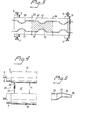
- the forming space, designated 17 in Figure 4 is defined laterally by side-walls 18 and 19 arranged between the belt sections 12' and 13'.
- the side-walls comprise, for example, polished stainless steel plate, plastic sheets or the like, and are impervious to air.
- the upper and lower edges of the side-walls lie in abutment with or are closely adjacent to respective belt sections 12' and 13', in order to achieve the best possible sealing effect.
- the side-walls 18 and 19 are stationary and are attached at the ends thereof to respective vertical bracket structures 20,21,22 and 23.
- a nozzle 24 Arranged at the inlet 15 is a nozzle 24 having a broad nozzle orifice 26, the width of which is preferably equal to the width B of the forming space, corresponding to the lateral distance between the two mutually parallel side-walls 18 and 19, so as to obtain the best possible distribution of fibre suspension blown into the forming space 17.
- This fibre suspension is supplied to the nozzle 24 from a source (not shown) through a pipe or conduit 25, and the pressure in the suspension is higher than the ambient surrounding pressure, which is normally equal to atmospheric pressure.
- the nozzle is suitably provided with at least one angled part or knee 27 (cf. Figure 5) operative in causing the flow of suspension to slow down and in forcing the fibres to spread laterally, as indicated by the arrows C in Figure 2.
- FIG. 1 there is shown in broken lines two suction devices 28 intended for removing dust by suction. More specifically, the sole purpose of these devices is to withdraw air which flows outwardly from the wires or conveyor belts and which may possibly contain fibres, these devices having a totally negligible effect on the pressure in the surrounding area.
- Fibres e.g. cellulose fibres, suspended in gas, preferably air, are blown into the inlet 15 and into the forming space 17 by means of the nozzle 24 at a suitable overpressure, for example a pressure of 600-700 mm water column, wc. Initially the outlet is blocked momentarily, in order to enable a fibre "plug" to form.
- a suitable overpressure for example a pressure of 600-700 mm water column, wc.
- This plug is required in order to prevent the fibre-air suspension, which may be injected into the forming space, for example, at a velocity of 20-25 m/s, from passing straight through the forming space, and forms in the forming space 17 an area of high fibre density, and is constantly renewed with fresh fibres as fibres as deposited on the conveyor belts as a result of the higher pressure which prevails in the forming space relative to the ambient surrounding. Because of the inherent velocity and overpressure of the fibre suspension, the deposition of fibres is controlled totally by the density of the fibre layers formed on respective belt sections 12' and 13', and when the conveyor belts 12 and 13 are set to travel at a suitable speed there is no risk of particles or fibres being slowed down and deposited on regions of dense fibre layers.
- the fibre mat produced in the arrangement according to Figures 1 and 2 have smooth mutually parallel side-edges formed by the two planar and mutually parallel side-walls 18,19. It is also possible, however, when practising the invention to produce a fibre mat or a fibre layer having the configuration illustrated in Figure 3, which shows the wire section 13' of the lower wire 13 facing towards the forming space 17.
- Firmly mounted around the whole parameter of the wire are profiled endless side-walls made of a flexible material, such as rubber for example.
- the side-walls are so profiled with inwardly directed bulges., 30,31 that the mutually opposite side-edges of the formed fibre mat are similarly recessed to form narrow or necked portions 32 at given locations along the side-edges.
- each side-wall 18,19 corresponds to the height H of the forming space 17, it must also be possible, in this latter case, to adjust the height of side-walls. As shown by the simplified illustration in Figure 4, this can be readily achieved by making each side-wall telescopic.
- the detail illustration of Figure 4 shows the left end- part of the two rolls 8,9 and a modified side-wall 35, corresponding to the side-wall 18 in Figure 1, seen from the inlet 15.
- the side-wall 35 is divided into a first upper wall-part 36 in the form of a twin-plate into which a lower wall-part 37 can be inserted, the ends of the two wall-parts 36,37 being displaceably mounted in, for example, the bracket structures 20 and 22 in Figure 1.
- the method and arrangement according to the invention provide an extremely uniform layer, thereby rendering it unnecessary to overdimension the thickness of the layer.
- a great saving in energy is achieved since the necessary overpressure can be obtained at a far lower cost than in the case of corresponding arrangements requiring a vacuum.
- the inner overpressure of the forming space 17 in relation to the pressure of the air surrounding the forming space can be readily varied by adjusting, for example, the velocity at which the fibre suspension is blown in the forming space.
Landscapes
- Health & Medical Sciences (AREA)
- Engineering & Computer Science (AREA)
- Animal Behavior & Ethology (AREA)
- General Health & Medical Sciences (AREA)
- Biomedical Technology (AREA)
- Heart & Thoracic Surgery (AREA)
- Vascular Medicine (AREA)
- Life Sciences & Earth Sciences (AREA)
- Manufacturing & Machinery (AREA)
- Epidemiology (AREA)
- Public Health (AREA)
- Veterinary Medicine (AREA)
- Nonwoven Fabrics (AREA)
- Absorbent Articles And Supports Therefor (AREA)
- Treatment Of Fiber Materials (AREA)
- Diaphragms For Electromechanical Transducers (AREA)
Applications Claiming Priority (2)
| Application Number | Priority Date | Filing Date | Title |
|---|---|---|---|
| SE8503292A SE455266B (sv) | 1985-07-02 | 1985-07-02 | Sett och anordning for att astadkomma ett fiberskikt |
| SE8503292 | 1985-07-02 |
Publications (2)
| Publication Number | Publication Date |
|---|---|
| EP0207909A2 true EP0207909A2 (fr) | 1987-01-07 |
| EP0207909A3 EP0207909A3 (fr) | 1987-11-25 |
Family
ID=20360783
Family Applications (1)
| Application Number | Title | Priority Date | Filing Date |
|---|---|---|---|
| EP86850185A Withdrawn EP0207909A3 (fr) | 1985-07-02 | 1986-05-23 | Dispositif pour fabriquer une couche fibreuse |
Country Status (6)
| Country | Link |
|---|---|
| US (1) | US4706340A (fr) |
| EP (1) | EP0207909A3 (fr) |
| DK (1) | DK312786A (fr) |
| FI (1) | FI862555A7 (fr) |
| NO (1) | NO862660L (fr) |
| SE (1) | SE455266B (fr) |
Cited By (1)
| Publication number | Priority date | Publication date | Assignee | Title |
|---|---|---|---|---|
| US4980226A (en) * | 1984-07-16 | 1990-12-25 | Molnlycke Ab | Fibrous absorption body for use in disposable articles |
Families Citing this family (2)
| Publication number | Priority date | Publication date | Assignee | Title |
|---|---|---|---|---|
| US6330735B1 (en) * | 2001-02-16 | 2001-12-18 | Kimberly-Clark Worldwide, Inc. | Apparatus and process for forming a laid fibrous web with enhanced basis weight capability |
| CN117158743A (zh) * | 2023-08-15 | 2023-12-05 | 山东谷悦康养器具有限公司 | 一种一体成型的分区双面体感空气纤维床垫及制造方法 |
Family Cites Families (10)
| Publication number | Priority date | Publication date | Assignee | Title |
|---|---|---|---|---|
| US2116663A (en) * | 1934-04-07 | 1938-05-10 | Johns Manville | Method and means for shaping felts of frangible fibers |
| US2195158A (en) * | 1938-09-02 | 1940-03-26 | Felix J Watts | Means for depositing separated fibers of fibrous material entrained in a stream of air in a continuous layer upon a traveling surface |
| BE475209A (fr) * | 1944-04-14 | |||
| US2715755A (en) * | 1949-11-22 | 1955-08-23 | Wood Conversion Co | Production and use of gaseous dispersions of solids and particularly of fibers |
| US2646381A (en) * | 1949-12-01 | 1953-07-21 | Wood Conversion Co | Method for dispersing and felting fibers and mill |
| US2729861A (en) * | 1951-11-01 | 1956-01-10 | United States Gypsum Co | Apparatus and method for making fibrous felts |
| US3058169A (en) * | 1956-07-16 | 1962-10-16 | Falls Paper & Power Company | Method and apparatus of forming batts and pads |
| US3332114A (en) * | 1964-01-13 | 1967-07-25 | Wood Conversion Co | Fiber dispersing and felting apparatus |
| US3396433A (en) * | 1965-02-23 | 1968-08-13 | Du Pont | Apparatus for making non-woven webs |
| DK144382C (da) * | 1977-11-08 | 1982-07-26 | Kroyer K K K | Apparat til fremstilling af et baneformet fiberprodukt |
-
1985
- 1985-07-02 SE SE8503292A patent/SE455266B/sv not_active IP Right Cessation
-
1986
- 1986-05-23 EP EP86850185A patent/EP0207909A3/fr not_active Withdrawn
- 1986-05-29 US US06/868,376 patent/US4706340A/en not_active Expired - Fee Related
- 1986-06-16 FI FI862555A patent/FI862555A7/fi not_active IP Right Cessation
- 1986-07-01 DK DK312786A patent/DK312786A/da not_active Application Discontinuation
- 1986-07-01 NO NO862660A patent/NO862660L/no unknown
Cited By (1)
| Publication number | Priority date | Publication date | Assignee | Title |
|---|---|---|---|---|
| US4980226A (en) * | 1984-07-16 | 1990-12-25 | Molnlycke Ab | Fibrous absorption body for use in disposable articles |
Also Published As
| Publication number | Publication date |
|---|---|
| SE8503292D0 (sv) | 1985-07-02 |
| SE455266B (sv) | 1988-07-04 |
| DK312786A (da) | 1987-01-03 |
| FI862555L (fi) | 1987-01-03 |
| NO862660D0 (no) | 1986-07-01 |
| DK312786D0 (da) | 1986-07-01 |
| FI862555A7 (fi) | 1987-01-03 |
| NO862660L (no) | 1987-01-05 |
| SE8503292L (sv) | 1987-01-03 |
| EP0207909A3 (fr) | 1987-11-25 |
| FI862555A0 (fi) | 1986-06-16 |
| US4706340A (en) | 1987-11-17 |
Similar Documents
| Publication | Publication Date | Title |
|---|---|---|
| US2618816A (en) | Bat forming apparatus and method | |
| EP1082081B1 (fr) | Procede et dispositif permettant de former par soufflage des ames absorbantes fibreuses | |
| US4927582A (en) | Method and apparatus for creating a graduated distribution of granule materials in a fiber mat | |
| US3973291A (en) | Method for forming fibrous pads | |
| US5466409A (en) | Forming belt for three-dimensional forming applications | |
| US6982052B2 (en) | Process and apparatus for air forming an article having a plurality of superimposed fibrous layers | |
| EP1360361B1 (fr) | Appareil et procede de formation d'une bande fibreuse aerolique dotee d'une meilleure capacite de masse surfacique | |
| US3994047A (en) | Apparatus for the twin-wire air laying of fibrous pads | |
| AU5527390A (en) | Apparatus for the shaping of articles of hygiene | |
| US3598680A (en) | Tandem air former | |
| KR100988697B1 (ko) | 섬유 흡수제품 내의 강화 웨브의 제어 배치 | |
| US3846871A (en) | Apparatus for forming fibrous pads | |
| US3501813A (en) | Method of forming a continuous fibrous web | |
| CA1316662C (fr) | Machine multi-tetes a former la toile | |
| US4706340A (en) | Method and an arrangement for producing a fibre layer | |
| US4904439A (en) | Method of making a non-woven fiber web using a multi-headed ductless webber | |
| US3943605A (en) | Fluff article and method and apparatus for forming same | |
| EP0388020B1 (fr) | Formation d'un coussin fibreux stratifié avec collerette | |
| GB2235754A (en) | Web drying machine | |
| JPH04227261A (ja) | おむつ類のための綿毛詰め物の製造装置 | |
| JPH01298219A (ja) | パッド製品形成装置及びパッドを形成する方法 | |
| SE508839C2 (sv) | Förfarande för framställning av absorberande struktur | |
| US4065832A (en) | Apparatus for forming a fibrous structure | |
| JP2659405B2 (ja) | ダクトなしのウエブ製造機 | |
| EP4613932A1 (fr) | Procédé et équipement d'etalement a l'air pour la fabrication de bandes présentant des bords latéraux precisement définis |
Legal Events
| Date | Code | Title | Description |
|---|---|---|---|
| PUAI | Public reference made under article 153(3) epc to a published international application that has entered the european phase |
Free format text: ORIGINAL CODE: 0009012 |
|
| AK | Designated contracting states |
Kind code of ref document: A2 Designated state(s): AT BE CH DE FR GB IT LI NL SE |
|
| PUAL | Search report despatched |
Free format text: ORIGINAL CODE: 0009013 |
|
| AK | Designated contracting states |
Kind code of ref document: A3 Designated state(s): AT BE CH DE FR GB IT LI NL SE |
|
| 17P | Request for examination filed |
Effective date: 19871123 |
|
| 17Q | First examination report despatched |
Effective date: 19880504 |
|
| STAA | Information on the status of an ep patent application or granted ep patent |
Free format text: STATUS: THE APPLICATION IS DEEMED TO BE WITHDRAWN |
|
| 18D | Application deemed to be withdrawn |
Effective date: 19890412 |
|
| RIN1 | Information on inventor provided before grant (corrected) |
Inventor name: AHLSTRAND, OVE |