EP0208079A1 - Sägemaschine - Google Patents
Sägemaschine Download PDFInfo
- Publication number
- EP0208079A1 EP0208079A1 EP86106146A EP86106146A EP0208079A1 EP 0208079 A1 EP0208079 A1 EP 0208079A1 EP 86106146 A EP86106146 A EP 86106146A EP 86106146 A EP86106146 A EP 86106146A EP 0208079 A1 EP0208079 A1 EP 0208079A1
- Authority
- EP
- European Patent Office
- Prior art keywords
- pressure
- cutting line
- support table
- beams
- sawing
- Prior art date
- Legal status (The legal status is an assumption and is not a legal conclusion. Google has not performed a legal analysis and makes no representation as to the accuracy of the status listed.)
- Granted
Links
Images


Classifications
-
- B—PERFORMING OPERATIONS; TRANSPORTING
- B23—MACHINE TOOLS; METAL-WORKING NOT OTHERWISE PROVIDED FOR
- B23D—PLANING; SLOTTING; SHEARING; BROACHING; SAWING; FILING; SCRAPING; LIKE OPERATIONS FOR WORKING METAL BY REMOVING MATERIAL, NOT OTHERWISE PROVIDED FOR
- B23D59/00—Accessories specially designed for sawing machines or sawing devices
- B23D59/006—Accessories specially designed for sawing machines or sawing devices for removing or collecting chips
- B23D59/0064—Accessories specially designed for sawing machines or sawing devices for removing or collecting chips by suction
-
- B—PERFORMING OPERATIONS; TRANSPORTING
- B23—MACHINE TOOLS; METAL-WORKING NOT OTHERWISE PROVIDED FOR
- B23D—PLANING; SLOTTING; SHEARING; BROACHING; SAWING; FILING; SCRAPING; LIKE OPERATIONS FOR WORKING METAL BY REMOVING MATERIAL, NOT OTHERWISE PROVIDED FOR
- B23D47/00—Sawing machines or sawing devices working with circular saw blades, characterised only by constructional features of particular parts
- B23D47/04—Sawing machines or sawing devices working with circular saw blades, characterised only by constructional features of particular parts of devices for feeding, positioning, clamping, or rotating work
-
- B—PERFORMING OPERATIONS; TRANSPORTING
- B23—MACHINE TOOLS; METAL-WORKING NOT OTHERWISE PROVIDED FOR
- B23Q—DETAILS, COMPONENTS, OR ACCESSORIES FOR MACHINE TOOLS, e.g. ARRANGEMENTS FOR COPYING OR CONTROLLING; MACHINE TOOLS IN GENERAL CHARACTERISED BY THE CONSTRUCTION OF PARTICULAR DETAILS OR COMPONENTS; COMBINATIONS OR ASSOCIATIONS OF METAL-WORKING MACHINES, NOT DIRECTED TO A PARTICULAR RESULT
- B23Q11/00—Accessories fitted to machine tools for keeping tools or parts of the machine in good working condition or for cooling work; Safety devices specially combined with or arranged in, or specially adapted for use in connection with, machine tools
- B23Q11/0042—Devices for removing chips
- B23Q11/0046—Devices for removing chips by sucking
-
- B—PERFORMING OPERATIONS; TRANSPORTING
- B23—MACHINE TOOLS; METAL-WORKING NOT OTHERWISE PROVIDED FOR
- B23Q—DETAILS, COMPONENTS, OR ACCESSORIES FOR MACHINE TOOLS, e.g. ARRANGEMENTS FOR COPYING OR CONTROLLING; MACHINE TOOLS IN GENERAL CHARACTERISED BY THE CONSTRUCTION OF PARTICULAR DETAILS OR COMPONENTS; COMBINATIONS OR ASSOCIATIONS OF METAL-WORKING MACHINES, NOT DIRECTED TO A PARTICULAR RESULT
- B23Q3/00—Devices holding, supporting, or positioning work or tools, of a kind normally removable from the machine
- B23Q3/02—Devices holding, supporting, or positioning work or tools, of a kind normally removable from the machine for mounting on a work-table, tool-slide, or analogous part
- B23Q3/06—Work-clamping means
- B23Q3/069—Work-clamping means for pressing workpieces against a work-table
-
- Y—GENERAL TAGGING OF NEW TECHNOLOGICAL DEVELOPMENTS; GENERAL TAGGING OF CROSS-SECTIONAL TECHNOLOGIES SPANNING OVER SEVERAL SECTIONS OF THE IPC; TECHNICAL SUBJECTS COVERED BY FORMER USPC CROSS-REFERENCE ART COLLECTIONS [XRACs] AND DIGESTS
- Y10—TECHNICAL SUBJECTS COVERED BY FORMER USPC
- Y10T—TECHNICAL SUBJECTS COVERED BY FORMER US CLASSIFICATION
- Y10T83/00—Cutting
- Y10T83/748—With work immobilizer
- Y10T83/7487—Means to clamp work
- Y10T83/7527—With equalizer or self-aligning jaw
-
- Y—GENERAL TAGGING OF NEW TECHNOLOGICAL DEVELOPMENTS; GENERAL TAGGING OF CROSS-SECTIONAL TECHNOLOGIES SPANNING OVER SEVERAL SECTIONS OF THE IPC; TECHNICAL SUBJECTS COVERED BY FORMER USPC CROSS-REFERENCE ART COLLECTIONS [XRACs] AND DIGESTS
- Y10—TECHNICAL SUBJECTS COVERED BY FORMER USPC
- Y10T—TECHNICAL SUBJECTS COVERED BY FORMER US CLASSIFICATION
- Y10T83/00—Cutting
- Y10T83/748—With work immobilizer
- Y10T83/7487—Means to clamp work
- Y10T83/754—Clamp driven by yieldable means
-
- Y—GENERAL TAGGING OF NEW TECHNOLOGICAL DEVELOPMENTS; GENERAL TAGGING OF CROSS-SECTIONAL TECHNOLOGIES SPANNING OVER SEVERAL SECTIONS OF THE IPC; TECHNICAL SUBJECTS COVERED BY FORMER USPC CROSS-REFERENCE ART COLLECTIONS [XRACs] AND DIGESTS
- Y10—TECHNICAL SUBJECTS COVERED BY FORMER USPC
- Y10T—TECHNICAL SUBJECTS COVERED BY FORMER US CLASSIFICATION
- Y10T83/00—Cutting
- Y10T83/768—Rotatable disc tool pair or tool and carrier
- Y10T83/7684—With means to support work relative to tool[s]
- Y10T83/773—Work-support includes passageway for tool [e.g., slotted table]
-
- Y—GENERAL TAGGING OF NEW TECHNOLOGICAL DEVELOPMENTS; GENERAL TAGGING OF CROSS-SECTIONAL TECHNOLOGIES SPANNING OVER SEVERAL SECTIONS OF THE IPC; TECHNICAL SUBJECTS COVERED BY FORMER USPC CROSS-REFERENCE ART COLLECTIONS [XRACs] AND DIGESTS
- Y10—TECHNICAL SUBJECTS COVERED BY FORMER USPC
- Y10T—TECHNICAL SUBJECTS COVERED BY FORMER US CLASSIFICATION
- Y10T83/00—Cutting
- Y10T83/768—Rotatable disc tool pair or tool and carrier
- Y10T83/7755—Carrier for rotatable tool movable during cutting
- Y10T83/7763—Tool carrier reciprocable rectilinearly
Definitions
- the present invention relates to a sawing machine for cutting workpieces such as panels or packs of panels, of the type comprising a horizontal workpiece support table having a straight longitudinal slot defining a cutting line, a sawing tool movable along the cutting line and a longitudinal pressure device arranged above the said workpiece support table and extending along the whole length of the cutting line.
- the said pressure device consists of two pressure beams arranged at both sides of the cutting line, parallelly thereto, means being provided for raising and lowering each pressure beam independently with respect to the other pressure beam, so as to raise and lower it with respect to the said workpiece support table in order to clamp thereon the workpiece to be sawed or to contact the surface of said support table.
- an auxiliary beam is arranged between the two pressure beams parallelly thereto and fixed with respect thereto, said auxiliary beam presenting at its bottom, at both sides facing the two pressure beams, a longitudinal sealing element extending for the whole length of the said auxiliary beam and contacting the inner faces of the pressure beams in such a manner as to form a duct along which the sawing tool is moved, said duct being connected to a suitable suction source for removing the saw dust resulting from the sawing operation.
- the sealing element is a continuous sealing strip having in section an inverted "U” shape and in which the free ends of the said sealing strip corresponding to the legs of the inverted "U” are in sealing contact with the inner faces of the vertically movable pressure beams.
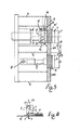
- reference letter A designates the horizontal workpiece support table of the sawing machine, which is provided with a rectilinear slot L defining a cutting line along which there is moved at least one disk saw S, suitably protruding therefrom, which cuts the pack of panels P suitably positioned on the workpiece support table A.
- the cutting line upstream and downstream with respect to the direction of movement of the panels P
- two identical hollow metal beams 1, 1' which are rectangular in section and are arranged in such a manner that one of their faces with smaller area is turned downward and it positioned parallel to the table A, respective strips 2, 2' of any suitable, sufficiently elastic and yielding material being attached to said lower faces.
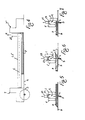
- the beams 1, 1' are closed by respective plates.3 which are fastened to slides 4, 4' cooperating with vertical guides 5, 105, 205, and 5', 105', and 205' which through supports 6, 6' are in turn secured to the adjoining frames 7, 7' provided at the ends of the cutting line.
- Fluid pressure operated, double acting cylinder and piston units 8, 8' are secured by their bodies to said frames, one for each end of the beams 1, 1', said units having their stems directed downwardly and secured to supports 9, 9' which are in their turn secured to slides 4, 4'.
- Each pair of units 8, 8' is fed through a respective circuit, so that it will be possible to move the pressure beams 1, 1' independently of each other.
- the chain 14 When the pressure device is in its rest position, as shown in Figure 2, the chain 14 is wound completely around the collar 12, and its remaining length, properly tensioned, is arranged vertically and is anchored to an adjusting screw 15 mounted onto a support secured to, frame 7.
- the chain 14' is instead entirely unwound, is vertically directed downwardly and by its other end is connected to an adjusting screw 16 mounted on a support 17 which is also secured to frame 7.
- the chains 14 are unwound from the collars 12 of bushings 11, 11' , and at the same time the chains 14' are wound around the collars 12', with the result that the beam 1 is moved constantly under a condition of parallelism with respect to the underlying table A.
- the small slacks which during time may arise in the chains 14, 14' can be easily recuperated by means of the adjusting screws 15, 16, or they can be recuperated automatically by elastic means suitably interposed between the said screws and the respective supports, as diagrammatically shown by reference numeral 18 in Figure 1.
- auxiliary beam 21 is provided which is parallel thereto and at equidistant position therefrom, said auxiliary beam 21 being secured by its ends to the guides 105,105', at one end directly, and at the other end with the interposition of a vertical duct 22 which opens by one extremity at the level of the lower side of said auxiliary beam, while by the other extremity is connected to a suitable suction circuit, as diagrammatically shown by arrow F in Figure 4.
- a continuous strip 23 of flexible material such as, for example, synthetic rubber, which has in cross section an inverted "U" profile and which by its edges contacts the inner vertical sides or faces of the pressure beams 1, 1'.
- both the pressure beams 1, 1' can be lowered of such an amount as to touch the workpiece support table A when no workpiece is present thereon, and also in this condition the beams 1, 1' remain with their inner sides in contact with the edges of the sealing strip 23, thus ensuring a structural continuity to said duct C.
- the pressure device according to the invention can operate as follows:
Landscapes
- Mechanical Engineering (AREA)
- Engineering & Computer Science (AREA)
- Sawing (AREA)
- Mechanical Treatment Of Semiconductor (AREA)
- Processing Of Stones Or Stones Resemblance Materials (AREA)
- Dicing (AREA)
- Stringed Musical Instruments (AREA)
- Polishing Bodies And Polishing Tools (AREA)
- Ultra Sonic Daignosis Equipment (AREA)
- Forklifts And Lifting Vehicles (AREA)
- Manufacturing And Processing Devices For Dough (AREA)
- Electrical Discharge Machining, Electrochemical Machining, And Combined Machining (AREA)
- Confectionery (AREA)
- Solid-Sorbent Or Filter-Aiding Compositions (AREA)
- Preparation Of Compounds By Using Micro-Organisms (AREA)
Priority Applications (1)
| Application Number | Priority Date | Filing Date | Title |
|---|---|---|---|
| AT86106146T ATE47347T1 (de) | 1985-05-10 | 1986-05-06 | Saegemaschine. |
Applications Claiming Priority (2)
| Application Number | Priority Date | Filing Date | Title |
|---|---|---|---|
| IT1517085U | 1985-05-10 | ||
| IT8515170U IT208464Z2 (it) | 1985-05-10 | 1985-05-10 | Pressore per macchine sezionatrici di pacchi di pannelli di legno e od altro materiale dotato di due organi di pressatura ad azionamento indipendente |
Publications (2)
| Publication Number | Publication Date |
|---|---|
| EP0208079A1 true EP0208079A1 (de) | 1987-01-14 |
| EP0208079B1 EP0208079B1 (de) | 1989-10-18 |
Family
ID=11146956
Family Applications (1)
| Application Number | Title | Priority Date | Filing Date |
|---|---|---|---|
| EP86106146A Expired EP0208079B1 (de) | 1985-05-10 | 1986-05-06 | Sägemaschine |
Country Status (11)
| Country | Link |
|---|---|
| US (1) | US4819532A (de) |
| EP (1) | EP0208079B1 (de) |
| JP (1) | JPH082521B2 (de) |
| AT (1) | ATE47347T1 (de) |
| BR (1) | BR8602100A (de) |
| CA (1) | CA1262857A (de) |
| DE (1) | DE3666380D1 (de) |
| DK (1) | DK161437C (de) |
| ES (1) | ES8703760A1 (de) |
| FI (1) | FI83403C (de) |
| IT (1) | IT208464Z2 (de) |
Cited By (10)
| Publication number | Priority date | Publication date | Assignee | Title |
|---|---|---|---|---|
| EP0249058A1 (de) | 1986-06-11 | 1987-12-16 | GIBEN IMPIANTI S.p.A. | Druckbalken für Sägemaschinen |
| EP1867419A1 (de) * | 2006-06-16 | 2007-12-19 | BIESSE S.p.A. | Sägemaschine zum Schneiden von Holzplatten oder degleichen |
| EP2105232A2 (de) | 2008-03-26 | 2009-09-30 | Firma HOLZMA Plattenaufteiltechnik GmbH | Plattenaufteilanlage |
| ITBO20090024A1 (it) * | 2009-01-21 | 2010-07-22 | Biesse Spa | Macchina sezionatrice per il taglio di pannelli di legno o simili |
| DE202011102022U1 (de) * | 2011-06-18 | 2012-07-05 | Otto Mayer Maschinenfabrik Gmbh | Sägemaschine mit Druckbalken |
| EP2944408A1 (de) * | 2014-04-30 | 2015-11-18 | BIESSE S.p.A. | Vorrichtung zum schneiden von holz- oder kunststoffscheiben |
| WO2016082821A1 (de) * | 2014-11-24 | 2016-06-02 | Kiesling Maschinentechnik Gmbh | Vorrichtung zur spanenden bearbeitung eines flächigen werkstücks |
| CN106042066A (zh) * | 2016-06-28 | 2016-10-26 | 巩振尧 | 一种自动化环保集屑型木材切割机 |
| CN109129739A (zh) * | 2018-09-18 | 2019-01-04 | 羊妙菜 | 一种建筑木材切割设备 |
| CN109465910A (zh) * | 2018-10-19 | 2019-03-15 | 嘉善顺源金属制品有限公司 | 一种便于收集碎屑的板材切割装置 |
Families Citing this family (22)
| Publication number | Priority date | Publication date | Assignee | Title |
|---|---|---|---|---|
| ES2052238T3 (es) * | 1990-02-21 | 1994-07-01 | Gfm Fertigungstechnik | Dispositivo para mecanizar especialmente piezas de trabajo puestas unas sobre otras. |
| JP2594004B2 (ja) * | 1992-08-05 | 1997-03-26 | ミサワホーム株式会社 | パネルの切断装置 |
| AT402704B (de) * | 1995-04-04 | 1997-08-25 | Ant Panhans Werkzeug Masch | Bearbeitungsvorrichtung für plattenförmige werkstücke, insbesondere plattenaufteilsäge |
| IT1299944B1 (it) * | 1998-03-31 | 2000-04-04 | Giben Impianti Spa | Dispositivo per il taglio di pannelli. |
| SE514645C2 (sv) | 1998-10-06 | 2001-03-26 | Perstorp Flooring Ab | Golvbeläggningsmaterial innefattande skivformiga golvelement avsedda att sammanfogas av separata sammanfogningsprofiler |
| DE29911462U1 (de) * | 1999-07-02 | 1999-11-18 | Akzenta Paneele & Profile Gmbh | Befestigungssystem für Paneele |
| RU2224070C2 (ru) | 1999-06-30 | 2004-02-20 | Акцента Панееле + Профиле Гмбх | Плита, а также система крепления для плит |
| US6299390B1 (en) * | 1999-12-22 | 2001-10-09 | Ballado Investments Inc. | Headpiece for machine tools that produce multiple holes |
| SE518184C2 (sv) | 2000-03-31 | 2002-09-03 | Perstorp Flooring Ab | Golvbeläggningsmaterial innefattande skivformiga golvelement vilka sammanfogas med hjälp av sammankopplingsorgan |
| DE20122553U1 (de) * | 2001-08-10 | 2006-03-23 | Akzenta Paneele + Profile Gmbh | Paneel sowie Befestigungssystem für Paneele |
| DE102010004717A1 (de) | 2010-01-15 | 2011-07-21 | Pergo (Europe) Ab | Set aus Paneelen umfassend Halteprofile mit einem separaten Clip sowie Verfahren zum Einbringen des Clips |
| CN104775594B (zh) | 2010-05-10 | 2017-09-22 | 佩尔戈(欧洲)股份公司 | 地板组件 |
| CN104139214B (zh) * | 2014-06-27 | 2016-06-22 | 中航复合材料有限责任公司 | 一种大型蜂窝块锯切固持方法 |
| CN106166769A (zh) * | 2016-08-30 | 2016-11-30 | 芜湖凯利达木业有限公司 | 一种木材可移动式切割装置 |
| JP6232534B1 (ja) * | 2017-05-26 | 2017-11-15 | 西澤 美砂子 | 鋸補助具 |
| CN107363910A (zh) * | 2017-09-11 | 2017-11-21 | 蒙山县天宇蚕具制品有限公司 | 一种蚕蔟用方木多片机 |
| EP3632600B1 (de) * | 2018-10-05 | 2023-08-23 | IMA Schelling Austria GmbH | Plattenaufteilanlage |
| CN109249088B (zh) * | 2018-10-20 | 2020-11-03 | 浙江荣鑫带钢有限公司 | 一种方便对异形钢材进行固定的钢材切割装置 |
| CN112720703A (zh) * | 2020-12-23 | 2021-04-30 | 赣州瓜瓜家居有限公司 | 一种高精准度的家具加工用剪切装置 |
| AU2022331993C1 (en) * | 2021-08-26 | 2025-08-14 | Yoshino Gypsum Co., Ltd. | Cutting device, apparatus for manufacturing gypsum board, and cutting method |
| CN114393644B (zh) * | 2022-02-24 | 2023-08-15 | 烟台春晖回转支承有限公司 | 一种具备除尘功能的数控机床及其除尘方法 |
| CN114851301B (zh) * | 2022-04-22 | 2023-03-28 | 江苏金智达工具有限公司 | 一种人字锯支架及使用方法 |
Citations (2)
| Publication number | Priority date | Publication date | Assignee | Title |
|---|---|---|---|---|
| DE2007183A1 (de) * | 1969-02-17 | 1970-09-17 | Wetoma Corp., Fort Worth, Tex. (V.St.A.) | Verfahren und Vorrichtung zum Herstellen von maßgerechten Platten |
| DE2435828A1 (de) * | 1973-10-30 | 1975-05-07 | Schelling & Co | Druckbalken fuer formatkreissaegen |
Family Cites Families (7)
| Publication number | Priority date | Publication date | Assignee | Title |
|---|---|---|---|---|
| US326916A (en) * | 1885-09-22 | Paper-cutting machine | ||
| US2987085A (en) * | 1958-08-01 | 1961-06-06 | Burke E Porter Machinery Co | Automatic sequencing wood saw and clamp |
| US3721140A (en) * | 1969-02-17 | 1973-03-20 | Wetoma Corp | Discharge unit for panel cutting apparatus |
| US4018118A (en) * | 1974-11-25 | 1977-04-19 | Goff Edward W | High speed precision metal cutting saw assembly |
| DE2706336C2 (de) * | 1977-02-15 | 1982-01-28 | Friedrich Wilhelm Dipl.-Ing. 5600 Wuppertal Elhaus | Kreissäge |
| CH631380A5 (de) * | 1978-07-31 | 1982-08-13 | Erwin Jenkner | Laengskreissaege mit unter dem tisch fahrendem saegeaggregat. |
| DE3113356C1 (de) * | 1981-04-02 | 1982-12-16 | Gustav Wagner Maschinenfabrik, 7410 Reutlingen | Werkstueckspannvorrichtung fuer eine Metall(kreis)saegemaschine |
-
1985
- 1985-05-10 IT IT8515170U patent/IT208464Z2/it active
-
1986
- 1986-05-06 EP EP86106146A patent/EP0208079B1/de not_active Expired
- 1986-05-06 AT AT86106146T patent/ATE47347T1/de not_active IP Right Cessation
- 1986-05-06 DE DE8686106146T patent/DE3666380D1/de not_active Expired
- 1986-05-06 FI FI861889A patent/FI83403C/fi not_active IP Right Cessation
- 1986-05-08 JP JP61103966A patent/JPH082521B2/ja not_active Expired - Lifetime
- 1986-05-09 CA CA000508824A patent/CA1262857A/en not_active Expired
- 1986-05-09 US US06/861,396 patent/US4819532A/en not_active Expired - Lifetime
- 1986-05-09 BR BR8602100A patent/BR8602100A/pt unknown
- 1986-05-09 ES ES554793A patent/ES8703760A1/es not_active Expired
- 1986-05-09 DK DK215186A patent/DK161437C/da not_active IP Right Cessation
Patent Citations (2)
| Publication number | Priority date | Publication date | Assignee | Title |
|---|---|---|---|---|
| DE2007183A1 (de) * | 1969-02-17 | 1970-09-17 | Wetoma Corp., Fort Worth, Tex. (V.St.A.) | Verfahren und Vorrichtung zum Herstellen von maßgerechten Platten |
| DE2435828A1 (de) * | 1973-10-30 | 1975-05-07 | Schelling & Co | Druckbalken fuer formatkreissaegen |
Cited By (14)
| Publication number | Priority date | Publication date | Assignee | Title |
|---|---|---|---|---|
| EP0249058A1 (de) | 1986-06-11 | 1987-12-16 | GIBEN IMPIANTI S.p.A. | Druckbalken für Sägemaschinen |
| EP1867419A1 (de) * | 2006-06-16 | 2007-12-19 | BIESSE S.p.A. | Sägemaschine zum Schneiden von Holzplatten oder degleichen |
| EP2105232A2 (de) | 2008-03-26 | 2009-09-30 | Firma HOLZMA Plattenaufteiltechnik GmbH | Plattenaufteilanlage |
| EP2105232A3 (de) * | 2008-03-26 | 2011-04-27 | Firma HOLZMA Plattenaufteiltechnik GmbH | Plattenaufteilanlage |
| ITBO20090024A1 (it) * | 2009-01-21 | 2010-07-22 | Biesse Spa | Macchina sezionatrice per il taglio di pannelli di legno o simili |
| EP2210719A1 (de) * | 2009-01-21 | 2010-07-28 | BIESSE S.p.A. | Verfahren zur Herstellung von Komponenten aus Holz oder Kunststoff |
| DE202011102022U1 (de) * | 2011-06-18 | 2012-07-05 | Otto Mayer Maschinenfabrik Gmbh | Sägemaschine mit Druckbalken |
| AT12974U1 (de) * | 2011-06-18 | 2013-03-15 | Otto Mayer Maschinenfabrik Gmbh | Sägemaschine mit Druckbalken |
| EP2944408A1 (de) * | 2014-04-30 | 2015-11-18 | BIESSE S.p.A. | Vorrichtung zum schneiden von holz- oder kunststoffscheiben |
| WO2016082821A1 (de) * | 2014-11-24 | 2016-06-02 | Kiesling Maschinentechnik Gmbh | Vorrichtung zur spanenden bearbeitung eines flächigen werkstücks |
| US10207377B2 (en) | 2014-11-24 | 2019-02-19 | Rittal Gmbh & Co. Kg | Device for machining a planar workpiece |
| CN106042066A (zh) * | 2016-06-28 | 2016-10-26 | 巩振尧 | 一种自动化环保集屑型木材切割机 |
| CN109129739A (zh) * | 2018-09-18 | 2019-01-04 | 羊妙菜 | 一种建筑木材切割设备 |
| CN109465910A (zh) * | 2018-10-19 | 2019-03-15 | 嘉善顺源金属制品有限公司 | 一种便于收集碎屑的板材切割装置 |
Also Published As
| Publication number | Publication date |
|---|---|
| US4819532A (en) | 1989-04-11 |
| FI83403C (fi) | 1991-07-10 |
| IT208464Z2 (it) | 1988-05-28 |
| DE3666380D1 (en) | 1989-11-23 |
| JPS6211601A (ja) | 1987-01-20 |
| EP0208079B1 (de) | 1989-10-18 |
| FI83403B (fi) | 1991-03-28 |
| DK161437C (da) | 1991-12-23 |
| FI861889A0 (fi) | 1986-05-06 |
| BR8602100A (pt) | 1987-01-13 |
| DK215186D0 (da) | 1986-05-09 |
| DK215186A (da) | 1986-11-11 |
| ES554793A0 (es) | 1987-03-01 |
| DK161437B (da) | 1991-07-08 |
| IT8515170V0 (it) | 1985-05-10 |
| ES8703760A1 (es) | 1987-03-01 |
| JPH082521B2 (ja) | 1996-01-17 |
| FI861889L (fi) | 1986-11-11 |
| CA1262857A (en) | 1989-11-14 |
| ATE47347T1 (de) | 1989-11-15 |
Similar Documents
| Publication | Publication Date | Title |
|---|---|---|
| EP0208079B1 (de) | Sägemaschine | |
| US4018134A (en) | Apparatus for trimming and edge-cutting a plate-like metallic workpiece | |
| EP0362569B1 (de) | Schachtelschneidevorrichtung und -verfahren | |
| US4031790A (en) | Lumber trimmer | |
| ATE223780T1 (de) | Verfahren und vorrichtung zum querteilen von bändern oder blechen in der walz-bzw transportlinie | |
| US5279196A (en) | Apparatus for cutting stacked, sheet-like material | |
| GB1362982A (en) | Apparatus for mating fabric workpieces | |
| KR870003856A (ko) | 판 분리장치 | |
| KR101129830B1 (ko) | 박판 유리의 꺾음 절단 장치 및 꺾음 절단 방법 | |
| US4151940A (en) | Apparatus for automatically loosening the marginal strip from a sheet of contour-cut glass | |
| CA2430757C (en) | Device for breaking the nicks connecting the blanks of a pile of cardboard sheets | |
| EP0249058B1 (de) | Druckbalken für Sägemaschinen | |
| US3768101A (en) | Trimming apparatus | |
| US3522825A (en) | Method and apparatus for sawing panels | |
| US4058040A (en) | Slotted worktable | |
| EP0508276B1 (de) | Doppelseitig wirkende Druckbalken für eine Schneidmaschine | |
| US3244047A (en) | Stock locating and severing device | |
| JPH11235617A (ja) | 板材の加工装置および加工方法 | |
| JPH08253336A (ja) | 薄板ガラスの折割方法およびその装置 | |
| US4363252A (en) | Multiple blade circular sawing machine | |
| US2901245A (en) | Plate positioning tables | |
| JPH0640575Y2 (ja) | 切断閉曲線入りガラス板の折割装置 | |
| JP3592612B2 (ja) | サンドイッチの切断装置 | |
| US4056993A (en) | Sheet slitter and punch assembly | |
| JPH0518009Y2 (de) |
Legal Events
| Date | Code | Title | Description |
|---|---|---|---|
| PUAI | Public reference made under article 153(3) epc to a published international application that has entered the european phase |
Free format text: ORIGINAL CODE: 0009012 |
|
| AK | Designated contracting states |
Kind code of ref document: A1 Designated state(s): AT BE DE SE |
|
| 17P | Request for examination filed |
Effective date: 19870416 |
|
| 17Q | First examination report despatched |
Effective date: 19880516 |
|
| GRAA | (expected) grant |
Free format text: ORIGINAL CODE: 0009210 |
|
| AK | Designated contracting states |
Kind code of ref document: B1 Designated state(s): AT BE DE SE |
|
| REF | Corresponds to: |
Ref document number: 47347 Country of ref document: AT Date of ref document: 19891115 Kind code of ref document: T |
|
| REF | Corresponds to: |
Ref document number: 3666380 Country of ref document: DE Date of ref document: 19891123 |
|
| PLBE | No opposition filed within time limit |
Free format text: ORIGINAL CODE: 0009261 |
|
| STAA | Information on the status of an ep patent application or granted ep patent |
Free format text: STATUS: NO OPPOSITION FILED WITHIN TIME LIMIT |
|
| 26N | No opposition filed | ||
| EAL | Se: european patent in force in sweden |
Ref document number: 86106146.3 |
|
| PGFP | Annual fee paid to national office [announced via postgrant information from national office to epo] |
Ref country code: BE Payment date: 20040510 Year of fee payment: 19 |
|
| PGFP | Annual fee paid to national office [announced via postgrant information from national office to epo] |
Ref country code: SE Payment date: 20040511 Year of fee payment: 19 |
|
| PGFP | Annual fee paid to national office [announced via postgrant information from national office to epo] |
Ref country code: DE Payment date: 20040513 Year of fee payment: 19 |
|
| PGFP | Annual fee paid to national office [announced via postgrant information from national office to epo] |
Ref country code: AT Payment date: 20040528 Year of fee payment: 19 |
|
| PG25 | Lapsed in a contracting state [announced via postgrant information from national office to epo] |
Ref country code: AT Free format text: LAPSE BECAUSE OF NON-PAYMENT OF DUE FEES Effective date: 20050506 |
|
| PG25 | Lapsed in a contracting state [announced via postgrant information from national office to epo] |
Ref country code: SE Free format text: LAPSE BECAUSE OF NON-PAYMENT OF DUE FEES Effective date: 20050507 |
|
| PG25 | Lapsed in a contracting state [announced via postgrant information from national office to epo] |
Ref country code: BE Free format text: LAPSE BECAUSE OF NON-PAYMENT OF DUE FEES Effective date: 20050531 |
|
| BERE | Be: lapsed |
Owner name: *GIBEN IMPIANTI S.P.A. Effective date: 20050531 |
|
| PG25 | Lapsed in a contracting state [announced via postgrant information from national office to epo] |
Ref country code: DE Free format text: LAPSE BECAUSE OF NON-PAYMENT OF DUE FEES Effective date: 20051201 |
|
| EUG | Se: european patent has lapsed | ||
| BERE | Be: lapsed |
Owner name: *GIBEN IMPIANTI S.P.A. Effective date: 20050531 |