EP0208143A1 - Steckerbuchse - Google Patents
Steckerbuchse Download PDFInfo
- Publication number
- EP0208143A1 EP0208143A1 EP86107695A EP86107695A EP0208143A1 EP 0208143 A1 EP0208143 A1 EP 0208143A1 EP 86107695 A EP86107695 A EP 86107695A EP 86107695 A EP86107695 A EP 86107695A EP 0208143 A1 EP0208143 A1 EP 0208143A1
- Authority
- EP
- European Patent Office
- Prior art keywords
- insulating body
- terminal
- connector socket
- terminals
- terminal board
- Prior art date
- Legal status (The legal status is an assumption and is not a legal conclusion. Google has not performed a legal analysis and makes no representation as to the accuracy of the status listed.)
- Granted
Links
- 239000002184 metal Substances 0.000 claims description 5
- 239000012774 insulation material Substances 0.000 claims description 3
- 238000005452 bending Methods 0.000 claims description 2
- 230000000694 effects Effects 0.000 description 4
- 230000004907 flux Effects 0.000 description 2
- 230000037431 insertion Effects 0.000 description 2
- 238000003780 insertion Methods 0.000 description 2
- 238000009413 insulation Methods 0.000 description 2
- 239000000758 substrate Substances 0.000 description 2
- 230000004308 accommodation Effects 0.000 description 1
- 230000009194 climbing Effects 0.000 description 1
- 230000007797 corrosion Effects 0.000 description 1
- 238000005260 corrosion Methods 0.000 description 1
- 230000006378 damage Effects 0.000 description 1
- 229910000679 solder Inorganic materials 0.000 description 1
- 238000005476 soldering Methods 0.000 description 1
Images



Classifications
-
- H—ELECTRICITY
- H01—ELECTRIC ELEMENTS
- H01R—ELECTRICALLY-CONDUCTIVE CONNECTIONS; STRUCTURAL ASSOCIATIONS OF A PLURALITY OF MUTUALLY-INSULATED ELECTRICAL CONNECTING ELEMENTS; COUPLING DEVICES; CURRENT COLLECTORS
- H01R13/00—Details of coupling devices of the kinds covered by groups H01R12/70 or H01R24/00 - H01R33/00
- H01R13/648—Protective earth or shield arrangements on coupling devices, e.g. anti-static shielding
-
- H—ELECTRICITY
- H01—ELECTRIC ELEMENTS
- H01R—ELECTRICALLY-CONDUCTIVE CONNECTIONS; STRUCTURAL ASSOCIATIONS OF A PLURALITY OF MUTUALLY-INSULATED ELECTRICAL CONNECTING ELEMENTS; COUPLING DEVICES; CURRENT COLLECTORS
- H01R13/00—Details of coupling devices of the kinds covered by groups H01R12/70 or H01R24/00 - H01R33/00
- H01R13/648—Protective earth or shield arrangements on coupling devices, e.g. anti-static shielding
- H01R13/658—High frequency shielding arrangements, e.g. against EMI [Electro-Magnetic Interference] or EMP [Electro-Magnetic Pulse]
-
- H—ELECTRICITY
- H01—ELECTRIC ELEMENTS
- H01R—ELECTRICALLY-CONDUCTIVE CONNECTIONS; STRUCTURAL ASSOCIATIONS OF A PLURALITY OF MUTUALLY-INSULATED ELECTRICAL CONNECTING ELEMENTS; COUPLING DEVICES; CURRENT COLLECTORS
- H01R12/00—Structural associations of a plurality of mutually-insulated electrical connecting elements, specially adapted for printed circuits, e.g. printed circuit boards [PCB], flat or ribbon cables, or like generally planar structures, e.g. terminal strips, terminal blocks; Coupling devices specially adapted for printed circuits, flat or ribbon cables, or like generally planar structures; Terminals specially adapted for contact with, or insertion into, printed circuits, flat or ribbon cables, or like generally planar structures
- H01R12/70—Coupling devices
- H01R12/71—Coupling devices for rigid printing circuits or like structures
- H01R12/712—Coupling devices for rigid printing circuits or like structures co-operating with the surface of the printed circuit or with a coupling device exclusively provided on the surface of the printed circuit
- H01R12/716—Coupling device provided on the PCB
-
- H—ELECTRICITY
- H01—ELECTRIC ELEMENTS
- H01R—ELECTRICALLY-CONDUCTIVE CONNECTIONS; STRUCTURAL ASSOCIATIONS OF A PLURALITY OF MUTUALLY-INSULATED ELECTRICAL CONNECTING ELEMENTS; COUPLING DEVICES; CURRENT COLLECTORS
- H01R12/00—Structural associations of a plurality of mutually-insulated electrical connecting elements, specially adapted for printed circuits, e.g. printed circuit boards [PCB], flat or ribbon cables, or like generally planar structures, e.g. terminal strips, terminal blocks; Coupling devices specially adapted for printed circuits, flat or ribbon cables, or like generally planar structures; Terminals specially adapted for contact with, or insertion into, printed circuits, flat or ribbon cables, or like generally planar structures
- H01R12/70—Coupling devices
- H01R12/71—Coupling devices for rigid printing circuits or like structures
- H01R12/72—Coupling devices for rigid printing circuits or like structures coupling with the edge of the rigid printed circuits or like structures
- H01R12/722—Coupling devices for rigid printing circuits or like structures coupling with the edge of the rigid printed circuits or like structures coupling devices mounted on the edge of the printed circuits
- H01R12/724—Coupling devices for rigid printing circuits or like structures coupling with the edge of the rigid printed circuits or like structures coupling devices mounted on the edge of the printed circuits containing contact members forming a right angle
-
- H—ELECTRICITY
- H01—ELECTRIC ELEMENTS
- H01R—ELECTRICALLY-CONDUCTIVE CONNECTIONS; STRUCTURAL ASSOCIATIONS OF A PLURALITY OF MUTUALLY-INSULATED ELECTRICAL CONNECTING ELEMENTS; COUPLING DEVICES; CURRENT COLLECTORS
- H01R12/00—Structural associations of a plurality of mutually-insulated electrical connecting elements, specially adapted for printed circuits, e.g. printed circuit boards [PCB], flat or ribbon cables, or like generally planar structures, e.g. terminal strips, terminal blocks; Coupling devices specially adapted for printed circuits, flat or ribbon cables, or like generally planar structures; Terminals specially adapted for contact with, or insertion into, printed circuits, flat or ribbon cables, or like generally planar structures
- H01R12/70—Coupling devices
- H01R12/71—Coupling devices for rigid printing circuits or like structures
- H01R12/72—Coupling devices for rigid printing circuits or like structures coupling with the edge of the rigid printed circuits or like structures
- H01R12/722—Coupling devices for rigid printing circuits or like structures coupling with the edge of the rigid printed circuits or like structures coupling devices mounted on the edge of the printed circuits
- H01R12/727—Coupling devices presenting arrays of contacts
-
- H—ELECTRICITY
- H01—ELECTRIC ELEMENTS
- H01R—ELECTRICALLY-CONDUCTIVE CONNECTIONS; STRUCTURAL ASSOCIATIONS OF A PLURALITY OF MUTUALLY-INSULATED ELECTRICAL CONNECTING ELEMENTS; COUPLING DEVICES; CURRENT COLLECTORS
- H01R13/00—Details of coupling devices of the kinds covered by groups H01R12/70 or H01R24/00 - H01R33/00
- H01R13/66—Structural association with built-in electrical component
- H01R13/70—Structural association with built-in electrical component with built-in switch
- H01R13/703—Structural association with built-in electrical component with built-in switch operated by engagement or disengagement of coupling parts, e.g. dual-continuity coupling part
Definitions
- the present invention relates to a connector socket which is mounted, for example, to a personal computer in order to connect personal computers.
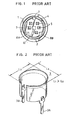
- the connector socket in question has a structure in which an annular recessed groove 2 is formed, as shown in Fig. 1, at one end surface (front surface) of an insulation body 1 to/from which the plug is inserted or removed and a cylindrical annular contact 3 as shown in Fig. 2 is engaged with the annular recessed groove 2.
- a plurality of female contact accommodating holes 5 are formed in a cylindrical portion of the insulation body 1 surrounded by the annular recessed groove 2. In this example, five female contact accommodating holes 5 are formed.
- the structure explained up to this step is similar to that of a connector sockot which is generally called the DIN type connector.
- the first feature of this connector socket is that in spite of being small in size it ensures a strong engaging force to a plug owing to a structure in which orthogonally crossing diameters L I and L 2 of the annular contact 3 are selected to be L 1 > L 2 as shown in Fig. 2 to form a cylindrical ellipse.
- annular contact 3 is formed as the cylindrical ellipse
- a sufficiently strong engaging force to a cylindrical metal cover 6 of plug 50 can be obtained when the plug 50 shown in Fig. 3 is inserted to the connector socket. Accordingly, a strong engaging force can be obtained even when the engaging area of the cylindrical metal cover 6 of the plug 50 is narrowed due to reduction in size of the plug. As a result, if a pulling force is applied to a cable 51 connected to the plug 50, a trouble that the plug 50 easily falls out the socket can be prevented.
- auxiliary recessed grooves 8A, 8B are formed, in addition to a main recessed groove 7 for positioning, in the circumference of a cylindrical column portion 4 surrounded by the annular recessed groove 2 as shown in Fig. 1.
- a main protrusion 9 for positioning and auxiliary protrusions 11A, 11B are formed to the internal surface of the cylindrical metal cover 6 of the plug 50 as shown in Fig. 3.
- the inserting positions are not confused by giving difference in size to the main protrusion 9 for positioning and the auxiliary protrusions 11A, 11B.
- a square hole 12 is formed in the cylindrical column portion 4 surrounded by the annular recessed groove 2 as shown in Fig. 1.
- This square hole 12 is engaged with an insulated square column 13 (in Fig. 3) provided to the plug 50 and this engagement also defines the correct engaging position between the plug and socket.
- This insulated square column 13 is formed a little longer than contact pins 14 of the plug 50. Owing to this structure, only when the insulated square column 13 enters the square hole 12 of socket, insertion of the contact pins 14 of the plug 50 to the female contact accommodation holes 5 can be allowed. As a result, there is no chance for the contact pins l4 of plug 50 to enter wrong female contact accommodating holes 5 of the socket.
- the connector socket proposed previously results in the effects such that a strong engaging force to the plug can be ensured even with a small-sized socket, a plug inserting position can be found easily and incorrect connection will never occur.
- a small-sized connector socket explained above has the structure which cannot be mounted directly on a printed circuit substrate because terminals for the female contacts are led out from the rear surface opposite to the plug inserting and removing surface.
- annular contact 3 does not perfectly cover the female contact up to the rear end side, sufficient shielding function by the annular contact 3 cannot be obtained. Therefore, in case this connector socket is used for connection with personal computer, for example, various disadvantages may be generated, namely, external noise enters from said connector socket and destroys data in the computer, and the signals sent or received through this connector socket may be sent therethrough to the outside.
- a terminal board is attached to a side surface of an insulateing body, a plurality of contact accommodating holes are formed to a cylindrical column portion of the insulating body surrounded by the annular recessed groove, female contacts accommodated in these female contact accommodating holes are bent and extended at a right angle at the rear surface of the insulating body, and such extended portions are positioned and inserted into the corresponding slots in the terminal board to project out therefrom as the terminals.
- An annular contact is mounted concentrically in the annular recessed groove and an earth terminal is formed integrally with the annular contact to protrude from the rear surface of the insulating body.
- the side surfaces of the insulating body, except for the side of the terminal board, is covered with a shield cover, which is mechanically and electrically coupled to the earth, terminal and a pair of earth terminals formed integrally with the shield cover are protruded on both sides of the terminal board in the protruding direction of the female contact terminals.
- the terminals protruded from this terminal board can directly be mounted on the printed circuit board and the contacts are shielded from the outside by the shield cover to reduce the influence of the external noise.
- the connector socket of the present invention has the following structural features, when viewed from the front side thereof, that the external side of annular recessed groove 2 of an insulating body 1 is square, an earth terminal 15 and female contact terminals 16 are protruded from one side surface of the insulating body 1.
- Earth terminals 17A, 17B extended integrally from a shield cover 17 are also protruded from the side where the earth terminal 15 of the insulating body 1 is protruded.
- eight female contact accommodating holes 5 are formed in a cylindrical column portion 4. In case eight female contact accommodating holes 5 are provided, the square hole 12 explained with respect to Fig. 1 is not provided.
- annular contact 3 is provided with the third earth terminal 15 in such a direction as orthogonally crossing the axial center, in addition to a pair of earth terminals 3A, 3B protruded from the rear end in parallel to the axial center of the annular contact 3.
- the annular contact 3 is inserted into an annular recessed groove 2 so that the third earth terminal 15 is disposed in a groove 18 formed in the front end face of the insulating body 1.
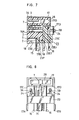
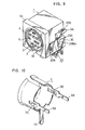
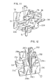
- Fig. 8 Fig. 9 and Fig. ll rear portions on both sides of external circumferential wall 19 of the annular recessed groove 2 are cut out to form open windows 21A, 21B communicating with the annular recessed groove 2.
- Tongue pieces 3C, 3D (Fig. 9) formed integrally with the annular contact 3 are engaged with the side edges of such open windows 21A, 21B, and thereby the annular contact 3 is fixed within the annular recessed groove 2.
- grooves 22A, 22B are respectively formed in the insulating body 1 below the open windows 21A, 21B in parallel to the plug inserting and removing direction P and a terminal board 23 of insulation material can be mounted to the insulating body 1 utilizing these grooves 22A, 22B.
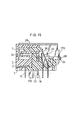
- the terminal board 23 comprises a bottom plate 23A, a pair of pawls 23Ba, 23Bb opposingly protruded from both side edges of the bottom plate 23A and a terminal support 23C formed integrally with the bottom plate at one side thereof to support the terminals 16, and the terminal board 23 is mounted to the insulating body 1 as shown in Fig. 9 by engaging the pawls 23Ba, 23Bb and the grooves 22A, 22B formed in the insulating body 1.
- Guide pillars 23D which guide the terminals are protruded from the terminal support 23C.
- a female contact 16A shown in Fig. 13 is inserted into each female contact accommodating hole 5 in the insulating body 1, the terminals l6 integrally extending from the rear ends of the female contacts 16A at a right angle thereto are arranged on the side of the terminal board 23.
- the terminals 16 are inserted into corresponding slots among a plurality of slots 23Ef, 23Er formed in the terminal support 23C of the terminal board 23A, and the terminal board 23 is pushed upwardly against the insulating body 1 to resiliently snap the pawls 23Ba, 23Bb into the grooves 22A, 22B as seen in Fig. 9.
- the terminals 16 are fixed to the terminal board 23.
- a cut-away 23G formed at the center of front edge of the terminal board 23 allows to pass therethrough the earth terminal 15 formed integrally with the annular contact 3. Owing to the cut-away 23G formed in the front marginal side of the terminal board 23, it is possible to prevent the flux, used at the time of soldering to the printed circuit board, from climbing along the earth terminal 15. Namely, when a narrow slot is formed in the plate 23 in place of the cut-away part 23G and the earth terminal 15 is inserted thereinto, a narrow gap may be formed between the earth terminal 15 and the inner surface of the slot, allowing the flux to climb through the narrow gap owing to the capillarity and extend along the circumferencial surface of the annular contact 3, causing corrosion of the annular contact 3. Therefore, in the case of this embodiment, the earth terminal 15 is passed through the cut-away part 23G so as not to produce the capillarity. However, if required, the earth terminal 15 may be passed through such slot in the terminal board 23, rather than through the cut-away part.
- a positioning protrusion 23F is formed integrally with the terminal board 23 on the plate 23A thereof at the center of an area in front of the terminal support 23C.
- an engaging part 1B is formed integrally with the insulating body 1 to engage between-the positioning protrusion 23F and terminal support 23C. The engagement of these engaging part 1B, the terminal support 23C and the positioning protrusion 23F determines the positioning of the terminal board 23 with respect to the insulating body 1 in forward and backward directions.
- the terminal support 23C is abutted to the rear surface of the insulating body 1.
- the terminal positioning slots 23Ef, 23Er are arranged in two rows: those rear slots 23Er are formed behind the guide pillars 23D in contact therewith and those front slots 23Ef are formed in the front surfaces of the guide pillars 23D to extend therealong.
- the guide pillars 23D separate a plurality of terminals 16 from one another and work as guides when being inserted between the front and rear rows of the terminals 16.
- the female contact terminals 16 are led out from one side surface of the socket, the terminals 16 can directly be connected to the printed circuit board (not shown) by mounting the socket thereon with the side surface being opposed to the printed circuit board.
- the present invention is also characterized in that the insulating body 1 is covered with the shield cover 17.
- the shield cover 17, for example, as shown in Fig. 14, has a U-shape formed by bending a press-cut conductive plate and the earth terminals 17A, 17B are provided to protrude from the ends of leg portions 17L, 17M of the U-shape.
- a pair of connecting pieces 17C, 17D are formed to extend from marginal rear sides of the both leg portions 17L, 17M the shield cover 17 and are bent toward each other. These connecting pieces 17C, 17D have cut-away portions 17E, 17F opened downward.
- Earth terminals 3A, 3B extended from the annular contact 3 are passed through the cut-away portions 17E, 17F, where the connecting pieces 17C, 17D and terminals 3A, 3B are respectively connected mechanically and electrically by solder 24 as shown in Figs. 6, 7 and 8 and thereby the shield cover 17 can be fixed to the insulating body 1.
- the shield cover 17 has the leg portions 17L, 17M each of which forms an angle a little smaller than right angle with respect to a central connecting portion 17H.
- leg portions 17L, 17M elastically hold the both sides of the terminal plate 23, thereby the shield cover 17 is held on the insulating body 1.
- a flange 1A is formed, as shown in Fig. 9, integrally with the insulating body 1 to extend in flush with the front surface of the insulating body 1 and the shield cover 17 is mounted on the insulating body 1 adjacent the rear surface of the flange 14 as shown in Fig. 5.
- Fig. 9 is formed, as shown in Fig. 9, integrally with the insulating body 1 to extend in flush with the front surface of the insulating body 1 and the shield cover 17 is mounted on the insulating body 1 adjacent the rear surface of the flange 14 as shown in Fig. 5.
- the positioning inward protrusions 17J, 17X are formed on inner surfaces of the leg portions 17L, 17M of the shield cover so as to be engaged between the pawls 23Ba, 23Bb and the terminal support 23C, thereby achieving the positioning of the shield cover 17 in forward and backward directions with respect to the insulating body 1.
- the connector socket of the present invention allows direct mounting to the printed circuit board. Moreover, the connector socket employs the structure in which the insulating body 1 is covered with the shield cover 17 over substantially the entire extent from the front end to the rear end thereof. Thus, it is possible to reduce external noises to be induced to the female contacts 16A and also possible to lower the leakage of signals flowing through the female contacts 16A.
- connection to the ground circuit of the printed circuit board is made through the three earth terminals 15, 3A and 33 of the annular contact 3 directly and via the earth terminals 17A, 17B of the shield cover 17, the electric resistances from the annular contact 3 and the shield cover 17 up to the ground become almost equal and differences in noise potential at respective points on the annular contact 3 and the shield cover 17 are reduced, resulting in improvement of the shielding effect. Therefore, in case the connector socket of the present invention is used for connection between computers, it is possible to reduce destruction of data due to entrance of external noises and ensure high reliability in sending and receiving of signals.
- the connector socket of the present invention can be fixedly supported to the printed circuit board by the earth terminals 17A, 17B protruded from the shield cover 17 in addition to the earth terminal 15 protruded from the annular contact 3. Therefore, a supporting force for the socket is strengthened and a trouble that the connector socket could come off from the printed circuit board would no longer happen even when a little excessive force is applied to the socket for insertion or removal of a plug.
- a conductive plate thicker than that used for the terminals l6 can be used for the shield cover 17, a strong supporting force can be ensured by connecting the earth terminals 17A, 17B of the shield cover 17 to the earth circuit of the printed circuit board.
- a mounting lug 17G may be provided at the marginal front side of the connecting portion 17H of the shield cover 17 so that the connector socket can be mounted directly to a schassis, etc.
- the supporting force for the connector socket can further be increased and the shielding effect can also be as much improved.
- the present invantion can be applied to a connector socket with a switch.
- a switch is formed with contact pieces 25, 26 supported by the plate 23A of the terminal board 23 and a rectangular plate-like actuator 27 made of an insulation material is provided inside a rectangular hole 28 which is open toward the rear end of the insulating body 1 so that the actuator 27 is slidably movable to project out from the hole 28 (see also Figs. 7, 8 and 11).
- the metal cover 6 of the plug 50 such as shown in Fig. 3 is inserted into the annular recessed groove 2, the protrusion 9 of the cover 6 pushes the actuator 27 backward to displace the upper end of a contact piece 26 apart from a contact piece 25, and thereby the switch is set to OFF state.
- a connector socket with switch which ensures high reliability for signals can be obtained by covering the connector socket of the structure as mentioned above with the shield cover 17.
Landscapes
- Details Of Connecting Devices For Male And Female Coupling (AREA)
- Cable Accessories (AREA)
- Connector Housings Or Holding Contact Members (AREA)
- Electron Tubes For Measurement (AREA)
Applications Claiming Priority (2)
| Application Number | Priority Date | Filing Date | Title |
|---|---|---|---|
| JP86148/85U | 1985-06-07 | ||
| JP1985086148U JPH0531824Y2 (de) | 1985-06-07 | 1985-06-07 |
Publications (2)
| Publication Number | Publication Date |
|---|---|
| EP0208143A1 true EP0208143A1 (de) | 1987-01-14 |
| EP0208143B1 EP0208143B1 (de) | 1990-02-28 |
Family
ID=13878653
Family Applications (1)
| Application Number | Title | Priority Date | Filing Date |
|---|---|---|---|
| EP86107695A Expired - Lifetime EP0208143B1 (de) | 1985-06-07 | 1986-06-05 | Steckerbuchse |
Country Status (6)
| Country | Link |
|---|---|
| US (1) | US4637669A (de) |
| EP (1) | EP0208143B1 (de) |
| JP (1) | JPH0531824Y2 (de) |
| KR (1) | KR900008801Y1 (de) |
| AT (1) | ATE50667T1 (de) |
| DE (1) | DE3669238D1 (de) |
Cited By (5)
| Publication number | Priority date | Publication date | Assignee | Title |
|---|---|---|---|---|
| EP0390929A4 (en) * | 1988-09-21 | 1991-10-16 | Hosiden Electronics Co., Ltd. | Socket with lock |
| EP0477856A3 (en) * | 1990-09-27 | 1993-04-21 | Hosiden Corporation | Socket |
| WO2006134420A1 (en) * | 2004-10-22 | 2006-12-21 | Ikonvergenz Pte Ltd | Audio visual connectors |
| WO2019158162A1 (de) * | 2018-02-19 | 2019-08-22 | Harting Electric Gmbh & Co. Kg | Leiterkartensteckverbinder mit einem schirmanbindungselement |
| CN112448209A (zh) * | 2019-08-29 | 2021-03-05 | 矢崎总业株式会社 | 屏蔽连接器 |
Families Citing this family (51)
| Publication number | Priority date | Publication date | Assignee | Title |
|---|---|---|---|---|
| USD298312S (en) | 1985-05-24 | 1988-11-01 | Hosiden Electronics Co., Ltd. | Electrical socket |
| USD298931S (en) | 1985-05-31 | 1988-12-13 | Hosiden Electronics Co., Ltd. | Electrical plug |
| JPS62154588A (ja) * | 1985-12-27 | 1987-07-09 | ヒロセ電機株式会社 | 電気コネクタ用シ−ルドケ−スおよびその製造方法 |
| US4836791A (en) * | 1987-11-16 | 1989-06-06 | Amp Incorporated | High density coax connector |
| JPH0339901Y2 (de) * | 1987-04-30 | 1991-08-22 | ||
| JPH0511671Y2 (de) * | 1987-08-17 | 1993-03-23 | ||
| US4842554A (en) * | 1988-06-03 | 1989-06-27 | Amp Incorporated | One-piece shield for a circular din |
| CA1303163C (en) * | 1988-06-03 | 1992-06-09 | Pete Cosmos | One-piece latching shield for a circular din connector |
| US4842555A (en) * | 1988-06-03 | 1989-06-27 | Amp Incorporated | Circular DIN receptacle cover for latching plug |
| US4995819A (en) * | 1988-06-03 | 1991-02-26 | Amp Incorporated | Set of strips of electrical terminals and a method of loading an electrical connector with said terminals |
| US4908335A (en) * | 1988-06-03 | 1990-03-13 | Amp Incorporated | One-piece molded insulating housing for a circular din connector |
| USD324846S (en) | 1988-08-24 | 1992-03-24 | Hosiden Electronics Co., Ltd. | Multi-pin socket |
| JPH0250983U (de) * | 1988-10-04 | 1990-04-10 | ||
| JPH0250989U (de) * | 1988-10-04 | 1990-04-10 | ||
| JPH0298074A (ja) * | 1988-10-04 | 1990-04-10 | Hirose Electric Co Ltd | 電気コネクタ |
| JPH0298075A (ja) * | 1988-10-04 | 1990-04-10 | Hirose Electric Co Ltd | 電気コネクタ |
| US4913664A (en) * | 1988-11-25 | 1990-04-03 | Molex Incorporated | Miniature circular DIN connector |
| EP0370833B1 (de) * | 1988-11-25 | 1995-04-19 | Molex Incorporated | Kreisförmiger Miniatur-Din-Verbinder |
| US5035651A (en) * | 1988-11-25 | 1991-07-30 | Molex Incorporated | Miniature circular DIN connector |
| US4878858A (en) * | 1988-12-13 | 1989-11-07 | Molex Incorporated | Low profile shielded jack |
| USD317903S (en) | 1989-01-13 | 1991-07-02 | Hosiden Electronics Co., Ltd. | Multi-pin socket |
| US4921431A (en) * | 1989-01-23 | 1990-05-01 | Switchcraft, Inc. | Connector adapter assembly |
| JPH02150682U (de) * | 1989-05-22 | 1990-12-27 | ||
| JPH0729586Y2 (ja) * | 1989-06-27 | 1995-07-05 | ホシデン株式会社 | コネクタ |
| JPH0332378U (de) * | 1989-08-07 | 1991-03-28 | ||
| JPH0754935Y2 (ja) * | 1990-02-02 | 1995-12-18 | ホシデン株式会社 | 縦形多連コネクタ |
| US5007862A (en) * | 1990-06-15 | 1991-04-16 | Amp Incorporated | Shielded connector having a multiply orientable housing |
| US5035650A (en) * | 1990-06-15 | 1991-07-30 | Amp Incorporated | Electrical connector having an inner metal shield |
| US5207597A (en) * | 1991-06-21 | 1993-05-04 | Amp Incorporated | Shielded connector with dual cantilever panel grounding beam |
| US5178562A (en) * | 1991-10-17 | 1993-01-12 | Epson Portland, Inc. | Contact member for miniature electrical circuit connector |
| US5288248A (en) * | 1991-10-28 | 1994-02-22 | Foxconn International | Totally shielded DIN connector |
| US5254010A (en) * | 1992-09-16 | 1993-10-19 | Amp Incorporated | Securing a surface mount electrical connector in a metal shielding shell |
| US5221212A (en) * | 1992-08-27 | 1993-06-22 | Amp Incorporated | Shielding a surface mount electrical connector |
| WO1994013039A1 (en) * | 1992-11-30 | 1994-06-09 | Berg Technology, Inc. | Reverse din connector assembly |
| US5902151A (en) * | 1997-05-30 | 1999-05-11 | The Whitaker Corporation | Circular din connector |
| EP1045484A1 (de) * | 1999-04-09 | 2000-10-18 | Molex Incorporated | Abgeschirmter elektrischer Verbinder |
| JP3333761B2 (ja) * | 1999-09-10 | 2002-10-15 | 株式会社ソニー・コンピュータエンタテインメント | シールドを備える電子機器、および、シールド部材 |
| USD444772S1 (en) | 2000-11-10 | 2001-07-10 | Henry Milan | Mold produced housing for enclosing the connection between a cable and a connector |
| TW547852U (en) | 2002-10-04 | 2003-08-11 | Hon Hai Prec Ind Co Ltd | Low profile connector |
| CN1301575C (zh) * | 2002-12-04 | 2007-02-21 | 富士康(昆山)电脑接插件有限公司 | 电连接器及其组装方法 |
| USD519925S1 (en) | 2004-04-19 | 2006-05-02 | Henry Milan | Housing for computer cable connector |
| JP4516819B2 (ja) * | 2004-10-20 | 2010-08-04 | 株式会社オーディオテクニカ | コンデンサマイクロホン |
| JP4640426B2 (ja) * | 2008-03-06 | 2011-03-02 | パナソニック電工株式会社 | レセプタクル |
| US8192209B1 (en) | 2009-01-09 | 2012-06-05 | Amazon Technologies, Inc. | Surface mount clip for routing and grounding cables |
| US7901221B1 (en) * | 2009-01-09 | 2011-03-08 | Amazon Technologies, Inc. | Universal serial bus ground clip |
| FR2969400B1 (fr) * | 2010-12-16 | 2013-08-30 | Radiall Sa | Connecteur pour carte de circuit imprime |
| US8817483B2 (en) * | 2011-08-01 | 2014-08-26 | Honeywell International Inc. | Connector assembly for a sensor |
| JP5884135B2 (ja) * | 2012-01-25 | 2016-03-15 | 矢崎総業株式会社 | コネクタユニット |
| US9484654B2 (en) * | 2014-04-10 | 2016-11-01 | Foxconn Interconnect Technology Limited | Electrical connector with improved contacts |
| DE202015100245U1 (de) * | 2015-01-21 | 2016-02-02 | FILTEC GmbH Filtertechnologie für die Elektronikindustrie | Steckerbuchsenanordnung umfassend eine abgeschirmte Steckerbuchse für Leiterplatten oder Platinen |
| US10827959B2 (en) * | 2015-11-11 | 2020-11-10 | Medtronic Minimed, Inc. | Sensor set |
Citations (4)
| Publication number | Priority date | Publication date | Assignee | Title |
|---|---|---|---|---|
| EP0040941A1 (de) * | 1980-05-28 | 1981-12-02 | AMP INCORPORATED (a New Jersey corporation) | Abschirmung für eine elektrische Steckverbindung |
| EP0118168A1 (de) * | 1983-01-31 | 1984-09-12 | AMP INCORPORATED (a New Jersey corporation) | Elektrischer Steckverbinder und Steckdose dafür |
| EP0122314A2 (de) * | 1983-03-10 | 1984-10-24 | PREH, Elektrofeinmechanische Werke Jakob Preh Nachf. GmbH & Co. | Mehrpolige Steckverbindung |
| EP0148532A1 (de) * | 1983-12-19 | 1985-07-17 | E.I. Du Pont De Nemours And Company | Elektrischer Steckverbinder für ein abgeschirmtes Kabel |
Family Cites Families (4)
| Publication number | Priority date | Publication date | Assignee | Title |
|---|---|---|---|---|
| DE2733634A1 (de) * | 1977-07-26 | 1979-02-08 | Daut & Rietz Kg | Mehrfachbuchse o.dgl. |
| US4486059A (en) * | 1982-09-20 | 1984-12-04 | Magnetic Controls Company | Receptacle assembly |
| JPS5947986U (ja) * | 1982-09-21 | 1984-03-30 | ティーディーケイ株式会社 | コネクタ |
| JPS5976081U (ja) * | 1982-11-15 | 1984-05-23 | 星電器製造株式会社 | コネクタソケツト |
-
1985
- 1985-06-07 JP JP1985086148U patent/JPH0531824Y2/ja not_active Expired - Lifetime
- 1985-10-28 US US06/791,869 patent/US4637669A/en not_active Expired - Lifetime
-
1986
- 1986-06-05 EP EP86107695A patent/EP0208143B1/de not_active Expired - Lifetime
- 1986-06-05 AT AT86107695T patent/ATE50667T1/de not_active IP Right Cessation
- 1986-06-05 DE DE8686107695T patent/DE3669238D1/de not_active Expired - Lifetime
- 1986-06-07 KR KR2019860008059U patent/KR900008801Y1/ko not_active Expired
Patent Citations (4)
| Publication number | Priority date | Publication date | Assignee | Title |
|---|---|---|---|---|
| EP0040941A1 (de) * | 1980-05-28 | 1981-12-02 | AMP INCORPORATED (a New Jersey corporation) | Abschirmung für eine elektrische Steckverbindung |
| EP0118168A1 (de) * | 1983-01-31 | 1984-09-12 | AMP INCORPORATED (a New Jersey corporation) | Elektrischer Steckverbinder und Steckdose dafür |
| EP0122314A2 (de) * | 1983-03-10 | 1984-10-24 | PREH, Elektrofeinmechanische Werke Jakob Preh Nachf. GmbH & Co. | Mehrpolige Steckverbindung |
| EP0148532A1 (de) * | 1983-12-19 | 1985-07-17 | E.I. Du Pont De Nemours And Company | Elektrischer Steckverbinder für ein abgeschirmtes Kabel |
Non-Patent Citations (1)
| Title |
|---|
| DIE BRÜCKE ZUM KUNDEN, vol. 51, January 1967, page 26; "Neue Steckbuchsen für gedruckte Schaltungsplatten" * |
Cited By (6)
| Publication number | Priority date | Publication date | Assignee | Title |
|---|---|---|---|---|
| EP0390929A4 (en) * | 1988-09-21 | 1991-10-16 | Hosiden Electronics Co., Ltd. | Socket with lock |
| EP0477856A3 (en) * | 1990-09-27 | 1993-04-21 | Hosiden Corporation | Socket |
| WO2006134420A1 (en) * | 2004-10-22 | 2006-12-21 | Ikonvergenz Pte Ltd | Audio visual connectors |
| WO2019158162A1 (de) * | 2018-02-19 | 2019-08-22 | Harting Electric Gmbh & Co. Kg | Leiterkartensteckverbinder mit einem schirmanbindungselement |
| US11309647B2 (en) | 2018-02-19 | 2022-04-19 | Harting Electric Gmbh & Co. Kg | Printed circuit board plug-in connector comprising a shielding connection element |
| CN112448209A (zh) * | 2019-08-29 | 2021-03-05 | 矢崎总业株式会社 | 屏蔽连接器 |
Also Published As
| Publication number | Publication date |
|---|---|
| JPS61201284U (de) | 1986-12-17 |
| KR870001260U (ko) | 1987-02-20 |
| JPH0531824Y2 (de) | 1993-08-16 |
| US4637669A (en) | 1987-01-20 |
| KR900008801Y1 (ko) | 1990-09-24 |
| EP0208143B1 (de) | 1990-02-28 |
| ATE50667T1 (de) | 1990-03-15 |
| DE3669238D1 (de) | 1990-04-05 |
Similar Documents
| Publication | Publication Date | Title |
|---|---|---|
| EP0208143B1 (de) | Steckerbuchse | |
| CN108258484B (zh) | 电连接器及其组合 | |
| US7074085B2 (en) | Shielded electrical connector assembly | |
| CN114361889B (zh) | 同轴连接器的浮动构造 | |
| US7179105B1 (en) | Power supply with a changeable plug element | |
| CN107978902B (zh) | 插座连接器 | |
| US4913664A (en) | Miniature circular DIN connector | |
| CN113437556B (zh) | 插头连接器、插座连接器以及连接器组件 | |
| KR100282629B1 (ko) | 전기접지시라우드 | |
| US5611711A (en) | Electrical connector assembly | |
| US8662927B2 (en) | Electrical connector for connecting to cables | |
| US7128607B2 (en) | Socket connector with reliable shielding member | |
| JP2005332749A (ja) | 電気コネクタ | |
| US6623301B2 (en) | Plug connector for electronic devices | |
| US5944559A (en) | Shielded electrical connector | |
| US6755691B2 (en) | Connector with movable contact alignment member | |
| JP2007180008A (ja) | コネクタプラグ | |
| KR910003912Y1 (ko) | 슬라이드스위치부착 코넥터소켓 | |
| EP0308490B1 (de) | Abgeschirmtes glied eines elektrischen steckverbinders mit montagemitteln | |
| US4466684A (en) | Low insertion force connector | |
| US20130337703A1 (en) | Electrical connector for connecting to cables | |
| JP2004259672A (ja) | 同軸コネクタ | |
| US5908331A (en) | Miniature din connector | |
| CN109980471B (zh) | 汇流条组件 | |
| US7241160B2 (en) | Shielded electrical connector for camera module |
Legal Events
| Date | Code | Title | Description |
|---|---|---|---|
| PUAI | Public reference made under article 153(3) epc to a published international application that has entered the european phase |
Free format text: ORIGINAL CODE: 0009012 |
|
| 17P | Request for examination filed |
Effective date: 19860605 |
|
| AK | Designated contracting states |
Kind code of ref document: A1 Designated state(s): AT BE CH DE FR GB IT LI LU NL SE |
|
| 17Q | First examination report despatched |
Effective date: 19880728 |
|
| GRAA | (expected) grant |
Free format text: ORIGINAL CODE: 0009210 |
|
| ITF | It: translation for a ep patent filed | ||
| AK | Designated contracting states |
Kind code of ref document: B1 Designated state(s): AT BE CH DE FR GB IT LI LU NL SE |
|
| REF | Corresponds to: |
Ref document number: 50667 Country of ref document: AT Date of ref document: 19900315 Kind code of ref document: T |
|
| REF | Corresponds to: |
Ref document number: 3669238 Country of ref document: DE Date of ref document: 19900405 |
|
| ET | Fr: translation filed | ||
| PLBE | No opposition filed within time limit |
Free format text: ORIGINAL CODE: 0009261 |
|
| STAA | Information on the status of an ep patent application or granted ep patent |
Free format text: STATUS: NO OPPOSITION FILED WITHIN TIME LIMIT |
|
| 26N | No opposition filed | ||
| ITTA | It: last paid annual fee | ||
| ITPR | It: changes in ownership of a european patent |
Owner name: TRASFORMAZIONE SOCIETARIA;HOSIDEN CORPORATION |
|
| REG | Reference to a national code |
Ref country code: CH Ref legal event code: PFA Free format text: HOSIDEN CORPORATION |
|
| REG | Reference to a national code |
Ref country code: FR Ref legal event code: CD |
|
| NLT1 | Nl: modifications of names registered in virtue of documents presented to the patent office pursuant to art. 16 a, paragraph 1 |
Owner name: HOSIDEN CORPORATION TE YAO, JAPAN. |
|
| EPTA | Lu: last paid annual fee | ||
| EAL | Se: european patent in force in sweden |
Ref document number: 86107695.8 |
|
| PGFP | Annual fee paid to national office [announced via postgrant information from national office to epo] |
Ref country code: BE Payment date: 19950511 Year of fee payment: 10 |
|
| PGFP | Annual fee paid to national office [announced via postgrant information from national office to epo] |
Ref country code: CH Payment date: 19950519 Year of fee payment: 10 |
|
| PGFP | Annual fee paid to national office [announced via postgrant information from national office to epo] |
Ref country code: LU Payment date: 19950601 Year of fee payment: 10 |
|
| PGFP | Annual fee paid to national office [announced via postgrant information from national office to epo] |
Ref country code: AT Payment date: 19950607 Year of fee payment: 10 |
|
| PGFP | Annual fee paid to national office [announced via postgrant information from national office to epo] |
Ref country code: NL Payment date: 19950627 Year of fee payment: 10 |
|
| PG25 | Lapsed in a contracting state [announced via postgrant information from national office to epo] |
Ref country code: LU Free format text: LAPSE BECAUSE OF NON-PAYMENT OF DUE FEES Effective date: 19960605 Ref country code: AT Effective date: 19960605 |
|
| PG25 | Lapsed in a contracting state [announced via postgrant information from national office to epo] |
Ref country code: LI Effective date: 19960630 Ref country code: CH Effective date: 19960630 Ref country code: BE Effective date: 19960630 |
|
| BERE | Be: lapsed |
Owner name: HOSIDEN ELECTRONICS CO. LTD Effective date: 19960630 |
|
| PG25 | Lapsed in a contracting state [announced via postgrant information from national office to epo] |
Ref country code: NL Effective date: 19970101 |
|
| REG | Reference to a national code |
Ref country code: CH Ref legal event code: PL |
|
| NLV4 | Nl: lapsed or anulled due to non-payment of the annual fee |
Effective date: 19970101 |
|
| REG | Reference to a national code |
Ref country code: GB Ref legal event code: IF02 |
|
| PGFP | Annual fee paid to national office [announced via postgrant information from national office to epo] |
Ref country code: GB Payment date: 20050601 Year of fee payment: 20 |
|
| PGFP | Annual fee paid to national office [announced via postgrant information from national office to epo] |
Ref country code: FR Payment date: 20050602 Year of fee payment: 20 |
|
| PGFP | Annual fee paid to national office [announced via postgrant information from national office to epo] |
Ref country code: SE Payment date: 20050607 Year of fee payment: 20 |
|
| PGFP | Annual fee paid to national office [announced via postgrant information from national office to epo] |
Ref country code: IT Payment date: 20050609 Year of fee payment: 20 |
|
| REG | Reference to a national code |
Ref country code: GB Ref legal event code: PE20 |
|
| PGFP | Annual fee paid to national office [announced via postgrant information from national office to epo] |
Ref country code: DE Payment date: 20050629 Year of fee payment: 20 |
|
| PG25 | Lapsed in a contracting state [announced via postgrant information from national office to epo] |
Ref country code: GB Free format text: LAPSE BECAUSE OF EXPIRATION OF PROTECTION Effective date: 20060604 |
|
| EUG | Se: european patent has lapsed |