EP0208400A2 - Ensemble modulaire d'embrayage - Google Patents
Ensemble modulaire d'embrayage Download PDFInfo
- Publication number
- EP0208400A2 EP0208400A2 EP86303464A EP86303464A EP0208400A2 EP 0208400 A2 EP0208400 A2 EP 0208400A2 EP 86303464 A EP86303464 A EP 86303464A EP 86303464 A EP86303464 A EP 86303464A EP 0208400 A2 EP0208400 A2 EP 0208400A2
- Authority
- EP
- European Patent Office
- Prior art keywords
- cover
- clutch
- spring
- set forth
- clutch assembly
- Prior art date
- Legal status (The legal status is an assumption and is not a legal conclusion. Google has not performed a legal analysis and makes no representation as to the accuracy of the status listed.)
- Withdrawn
Links
Images


Classifications
-
- F—MECHANICAL ENGINEERING; LIGHTING; HEATING; WEAPONS; BLASTING
- F16—ENGINEERING ELEMENTS AND UNITS; GENERAL MEASURES FOR PRODUCING AND MAINTAINING EFFECTIVE FUNCTIONING OF MACHINES OR INSTALLATIONS; THERMAL INSULATION IN GENERAL
- F16D—COUPLINGS FOR TRANSMITTING ROTATION; CLUTCHES; BRAKES
- F16D13/00—Friction clutches
- F16D13/22—Friction clutches with axially-movable clutching members
- F16D13/38—Friction clutches with axially-movable clutching members with flat clutching surfaces, e.g. discs
- F16D13/46—Friction clutches with axially-movable clutching members with flat clutching surfaces, e.g. discs in which two axially-movable members, of which one is attached to the driving side and the other to the driven side, are pressed from one side towards an axially-located member
- F16D13/48—Friction clutches with axially-movable clutching members with flat clutching surfaces, e.g. discs in which two axially-movable members, of which one is attached to the driving side and the other to the driven side, are pressed from one side towards an axially-located member with means for increasing the effective force between the actuating sleeve or equivalent member and the pressure member
- F16D13/50—Friction clutches with axially-movable clutching members with flat clutching surfaces, e.g. discs in which two axially-movable members, of which one is attached to the driving side and the other to the driven side, are pressed from one side towards an axially-located member with means for increasing the effective force between the actuating sleeve or equivalent member and the pressure member in which the clutching pressure is produced by springs only
-
- F—MECHANICAL ENGINEERING; LIGHTING; HEATING; WEAPONS; BLASTING
- F16—ENGINEERING ELEMENTS AND UNITS; GENERAL MEASURES FOR PRODUCING AND MAINTAINING EFFECTIVE FUNCTIONING OF MACHINES OR INSTALLATIONS; THERMAL INSULATION IN GENERAL
- F16D—COUPLINGS FOR TRANSMITTING ROTATION; CLUTCHES; BRAKES
- F16D13/00—Friction clutches
- F16D13/58—Details
- F16D13/70—Pressure members, e.g. pressure plates, for clutch-plates or lamellae; Guiding arrangements for pressure members
Definitions
- a clutch assembly for the manual transmission of an automotive vehicle presently consists of a relatively heavy flywheel bolted to a flange on the vehicle engine drive shaft, a cover which has a peripheral radial flange bolted to the flywheel, an annular pressure plate received in the cover and having peripheral lugs for securement to a plurality of flexible drive straps which have their opposite ends secured to the cover, a clutch plate positioned between and having friction facings adapted to engage the facing surfaces of the flywheel and pressure plate, and a diaphragm spring pivotally mounted in the cover and engaging the pressure plate to urge it towards the flywheel.
- the clutch plate is mounted on the splined end of a transmission input shaft to rotate the shaft upon clutch engagement, and a release bearing is mounted for axial movement on the input shaft to engage the fingers of the diaphragm spring and disengage the clutch plate.
- a customer has to purchase these parts separately and install them as separate items to form the clutch assembly.
- the clutch components of the present invention are formed as a modular assembly which the customer receives as a package and easily installs without the alignment and tolerance problems previously encountered.
- the present invention comprehends the provision of a novel modular clutch assembly that is preassembled and ready for installation between the engine drive shaft and the transmission input shaft for a manual transmission of an automotive vehicle.
- the purchaser has only to make a single installation rather than separate installations of three items; namely, flywheel, driven member assembly and cover plate assembly.
- the present invention also comprehends the provision of a novel modular clutch assembly wherein the normal mounting lugs on the annular pressure plate are eliminated and additional mass added to the outer diameter of the pressure plate.
- the drive straps have been omitted and a plurality of control clips or springs are secured to the periphery of the pressure plate and to the clutch cover to provide both the drive connection therebetween and the retraction force to disengage the clutch.
- the present invention further comprehends the provision of a novel clutch assembly having a diaphragm spring pivot plate for the clutch cover assembly wherein substantially continuous circular depressions in the cover and in the pivot plate provide the opposed pivot surfaces for the diaphragm spring. Also, the pivot plate provides centering tabs which are received in the enlarged openings defining the inner ends of the diaphragm spring fingers.
- a novel clutch assembly having a plurality of individual shields secured to the outer periphery of the clutch cover and acting in conjunction with openings in the cover as air flow guides to enhance cooling air flow through the clutch assembly.
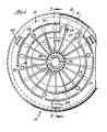
- Figures 1 and 2 disclose a modular clutch assembly 10 to be utilized for a manual transmission in an automotive vehicle (not shown), which clutch assembly includes a circular flywheel 11 mounted on a retainer/ring gear 12 by bolts 13 or other suitable securing means in a manner similar to the mounting of a torque converter; the retainer 12 being suitably secured to the engine crank shaft (not shown).
- a clutch cover 14 comprises a generally annular member having a central opening defined by a curved inner lip 15 and having an outer axially extending flange 16 receiving and secured onto the periphery 17 of the flywheel 11 as by welding at 18.
- the cover 14 has an interrupted substantially annular depression 19 forming a pivot surface 21 for a Belleville spring 22 mounted on a plurality of circumferentially equally spaced rivets 23 secured in openings in the cover adjacent the depression; each rivet having an enlarged head 24 locating a wire pivot ring 25 directly opposite to the pivot surface 21.
- the rivets are received in enlarged openings 27 formed at the inner ends of radial slots defining inwardly extending spring fingers 26 for the spring 22.
- the pressure plate includes a generally annular fulcrum surface 29 adjacent its outer periphery to be engaged by the outer portion 31 of the Belleville spring 22.
- the driven plate assembly 32 includes a clutch plate 33 suitably secured to a central hub 34 having an internally splined passage 35 adapted to receive the splined end 36 of a transmission input shaft 37 leading to a manual transmission (not shown) for the vehicle.
- the clutch plate 33 extends radially outwardly between the facing friction surfaces 38 and 39 of the flywheel 11 and pressure plate 28, respectively, and annular friction facings 41,41 are secured to the opposite surfaces of the clutch plate to engage the friction surfaces 38 and 39.
- the conventional mounting lugs on the pressure plate and drive straps extending between the lugs and the cover were eliminated and replaced by a plurality of return clips 43, each of which includes a generally rectangular mounting base 44 with a central opening 45 receiving a rivet 46 secured to the periphery 47 of the pressure plate.
- An inwardly bent strap portion 48 terminates in a clip portion 49 which extends through a slot 51 in the cover to resiliently engage the edge of the slot.
- the only part that may be slightly out of alignment is the driven plate member 32 which is only retained between the flywheel and the pressure plate by the force of the diaphragm spring.
- a bonded facing/cushion spring arrangement may be used, and a damper may separate and cushion the clutch facing area from the hub.
- This modular clutch design eliminates the outer radial mounting flange normally provided on the clutch cover to bolt the cover to the flywheel and, in combination with the elimination of the mounting lugs on the pressure plate, allow for a larger circumference driven member and pressure plate in a very small environment.
- the larger drive plate and pressure plate acts to smooth out engine performance and changes the drive line harmonics. Also, the close tolerances for the pressure plate are ameliorated.
- the elimination of the normal mounting lugs on the pressure plate allows for a larger plate circumference to provide additional mass; the extra mass increasing the inertia of the pressure plate while still maintaining a comparable component weight.
- FIG 4 is a partial view of the modular clutch assembly 10a with an alternate driving and retracting means for the pressure plate.
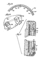
- the return clips of Figure 3 are replaced by control springs 55 which are formed of steel spring wire to provide a central loop 56 between a pair of oppositely extending legs 57,57.
- One leg of each spring has an offset 58 ( Figure 7) to provide proper fit and clearance of the spring between the pressure plate 28a and cover 14a.
- the spring legs terminate in bent ends or hooks 59,59 having detents 61,61 received in slots 62,62 in the clutch cover flange 16a, and the spring is secured to the periphery of the pressure plate 28a by a rivet 46a extending through the loop 56.
- An opening 63 is located in the cover flange 16a opposite to and receiving the loop and rivet head to provide stabilizing stops when shipping cover assemblies minus the flywheel and/or driven member assembly.
- the control spring 55 as assembled in Figures 4 and 5, is under tension in the normal engaged mode of the clutch assembly. As the clutch is disengaged, the spring will resume its "free" position prior to assembly, thereby pulling the pressure plate away from the driven member assembly.
- the two legs 57 and hooks 59 on the spring provide a positive driving means between the cover and pressure plate during both normal and coasting operations.
- each shield 65 also has positioning tabs 68 bent out of the sides and spaced from the barbs to contact the cover flange when the shield is properly assembled. Projections 69 at the rear of the shield and 70 on the sides forward of barbs 66 act to position the shield radially.
- a forward extension 71 acts to cover the protruding hook 59 of a control spring and an opening 72 in the flange 16a and provides a mouth 73 to induce air flow for cooling the clutch.
- the shield is curved and with the sides 67 provides a tapered contour.
- the extension 71 provides the "leading edge" of the shield so that a slight vacuum is created at the opening 73 drawing air through the opening 72 and the clutch assembly for a cooling effect to increase the effective capacity of the clutch.
- Figures 9 and 10 disclose an alternate form of control spring 75 for the clutch assembly similar to control spring 55.
- This spring also includes a central loop 76 and a pair of oppositely extending legs 77, each offset at 78 in opposite directions from the loop. Each leg terminates in a generally U-shaped portion 79 with hooks 81 bent at the free ends received in slots 62b in flange 16b.
- a rivet 46b projects through the loop 76 to secure the spring to the periphery of the pressure plate 28b, and rivets 82 are received in the U-bends 79 and secured to the cover flange 16b.
- the control spring 75 can pivot about the rivets 82.
- a pivot ring 85 replaces the rivets 23 shown in Figures 1 and 2.
- This annular pivot ring 85 has a slot 86 therein to allow the ring to expand and fit the diaphragm spring 22, and incorporates a single formed substantially circular fulcrum bead 87 positioned opposite the generally circular fulcrum bead or pivot surface 21 in the clutch cover 14 on the opposite side of the diaphragm spring, and a plurality of circumferentially spaced integral tabs 88 extending rearwardly from the plate through openings 27 in the spring to a formed surface or shoulder 89 and then through slots 91 in the cover with the outer ends 92 bent over to clamp the cover between the bent end 92 and shoulder 89. Also, a plurality of circumferentially spaced centering tabs 93 alternate with the tabs 88 and are bent over and are positioned within other enlarged openings 27 separating the spring fingers 26.
- This single formed pivot ring 85 attaches the Belleville spring to the cover stamping in a positive fashion and eliminates numerous loose parts.
- the ring also acts as a spacer to properly preload the Belleville spring and properly locate the spring relative to the cover.
- the integral tabs 88 having the surfaces 89 and bent formed ends 92 provide the proper clamping action at the spring when abutting the underside of the cover at the pivot surface or bead.
Landscapes
- Engineering & Computer Science (AREA)
- General Engineering & Computer Science (AREA)
- Mechanical Engineering (AREA)
- Mechanical Operated Clutches (AREA)
Applications Claiming Priority (2)
| Application Number | Priority Date | Filing Date | Title |
|---|---|---|---|
| US73832885A | 1985-05-28 | 1985-05-28 | |
| US738328 | 1985-05-28 |
Publications (2)
| Publication Number | Publication Date |
|---|---|
| EP0208400A2 true EP0208400A2 (fr) | 1987-01-14 |
| EP0208400A3 EP0208400A3 (fr) | 1987-04-22 |
Family
ID=24967534
Family Applications (1)
| Application Number | Title | Priority Date | Filing Date |
|---|---|---|---|
| EP86303464A Withdrawn EP0208400A3 (fr) | 1985-05-28 | 1986-05-07 | Ensemble modulaire d'embrayage |
Country Status (3)
| Country | Link |
|---|---|
| EP (1) | EP0208400A3 (fr) |
| JP (1) | JPS61278624A (fr) |
| BR (1) | BR8602395A (fr) |
Cited By (11)
| Publication number | Priority date | Publication date | Assignee | Title |
|---|---|---|---|---|
| FR2608704A1 (fr) * | 1986-12-17 | 1988-06-24 | Luk Lamellen & Kupplungsbau | Unite d'embrayage a friction |
| FR2661722A1 (fr) * | 1990-05-07 | 1991-11-08 | Fichtel & Sachs Ag | Ensemble a embrayage a friction et son procede de realisation. |
| FR2732736A1 (fr) * | 1995-04-06 | 1996-10-11 | Valeo | Mecanisme d'embrayage a couvercle en deux parties pour embrayage a diaphragme, notamment pour vehicule automobile |
| EP0780589A1 (fr) * | 1995-12-20 | 1997-06-25 | Valeo | Module d'embrayage dont le couvercle est fixé sur un flasque de support par des pattes transversales |
| EP0780588A1 (fr) * | 1995-12-20 | 1997-06-25 | Valeo | Module d'embrayage comportant une cible définissant des créneaux |
| FR2749049A1 (fr) * | 1996-05-23 | 1997-11-28 | Exedy Corp | Embrayage modulaire et sa structure |
| US6142276A (en) * | 1998-06-19 | 2000-11-07 | Sachs Race Engineering Gmbh | Housing for a multiplate clutch |
| FR2944770A1 (fr) * | 2009-04-27 | 2010-10-29 | Peugeot Citroen Automobiles Sa | Dispositif de montage d'un organe de friction et procede de montage de l'organe sur un arbre. |
| CN110821980A (zh) * | 2019-11-08 | 2020-02-21 | 苏州宝洪泰电子有限公司 | 汽车离合器用高弹性压紧弹片 |
| CN112192209A (zh) * | 2020-09-30 | 2021-01-08 | 重庆传动轴股份有限公司 | 一种传动轴压装焊接一体机 |
| CN112326695A (zh) * | 2020-10-30 | 2021-02-05 | 上海航天设备制造总厂有限公司 | 用于检测环形焊缝的周向x射线仪对心装置 |
Family Cites Families (9)
| Publication number | Priority date | Publication date | Assignee | Title |
|---|---|---|---|---|
| GB552952A (en) * | 1941-03-17 | 1943-04-30 | Borg And Beck Company Ltd | Improvements in or relating to friction clutches |
| US2765892A (en) * | 1952-10-11 | 1956-10-09 | Borg Warner | Friction clutch assembly |
| GB1434601A (en) * | 1973-01-02 | 1976-05-05 | Gkn Transmissions Ltd | Clutches |
| ES439478A1 (es) * | 1975-07-16 | 1977-02-01 | Hijos De J M Aranceta S A | Perfeccionamientos en los dispositivos de disco de friccion. |
| FR2508123B1 (fr) * | 1981-06-19 | 1986-05-23 | Valeo | Mecanisme d'embrayage, notamment pour vehicule automobile |
| US4478324A (en) * | 1982-04-14 | 1984-10-23 | Dana Corporation | Resilient drive means for a clutch |
| FR2526105A1 (fr) * | 1982-04-29 | 1983-11-04 | Valeo | Embrayage, notamment pour vehicule automobile, avec un assemblage ameliore du couvercle sur le plateau de reaction |
| FR2546595B1 (fr) * | 1983-05-24 | 1988-12-30 | Valeo | Mecanisme d'embrayage et plateau de pression pour un tel mecanisme d'embrayage, notamment pour vehicule automobile |
| JPS59219527A (ja) * | 1983-05-26 | 1984-12-10 | Fuji Tekkosho:Kk | クラツチ通風装置の防水構造 |
-
1986
- 1986-05-07 EP EP86303464A patent/EP0208400A3/fr not_active Withdrawn
- 1986-05-27 BR BR8602395A patent/BR8602395A/pt unknown
- 1986-05-27 JP JP12205586A patent/JPS61278624A/ja active Pending
Cited By (19)
| Publication number | Priority date | Publication date | Assignee | Title |
|---|---|---|---|---|
| FR2608704A1 (fr) * | 1986-12-17 | 1988-06-24 | Luk Lamellen & Kupplungsbau | Unite d'embrayage a friction |
| GB2202286A (en) * | 1986-12-17 | 1988-09-21 | Luk Lamellen & Kupplungsbau | A friction clutch unit |
| US4883153A (en) * | 1986-12-17 | 1989-11-28 | Luk Lamellen Und Kupplungsbau Gmbh | Friction clutch |
| DE4014470C2 (de) * | 1990-05-07 | 1999-05-27 | Mannesmann Sachs Ag | Reibungskupplung |
| DE4014470A1 (de) * | 1990-05-07 | 1991-11-14 | Fichtel & Sachs Ag | Verfahren zur montage einer reibungskupplung |
| FR2661722A1 (fr) * | 1990-05-07 | 1991-11-08 | Fichtel & Sachs Ag | Ensemble a embrayage a friction et son procede de realisation. |
| FR2732736A1 (fr) * | 1995-04-06 | 1996-10-11 | Valeo | Mecanisme d'embrayage a couvercle en deux parties pour embrayage a diaphragme, notamment pour vehicule automobile |
| DE19611504A1 (de) * | 1995-04-06 | 1997-02-06 | Valeo | Kupplungsmechanismus mit zweiteiligem Deckel für eine Membranfederkupplung, insbesondere für Kraftfahrzeuge |
| FR2742827A1 (fr) * | 1995-12-20 | 1997-06-27 | Valeo | Module d'embrayage dont le couvercle est fixe sur un flasque de support par des pattes transversales |
| FR2742825A1 (fr) * | 1995-12-20 | 1997-06-27 | Valeo | Module d'embrayage comportant une cible definissant des creneaux |
| EP0780588A1 (fr) * | 1995-12-20 | 1997-06-25 | Valeo | Module d'embrayage comportant une cible définissant des créneaux |
| EP0780589A1 (fr) * | 1995-12-20 | 1997-06-25 | Valeo | Module d'embrayage dont le couvercle est fixé sur un flasque de support par des pattes transversales |
| FR2749049A1 (fr) * | 1996-05-23 | 1997-11-28 | Exedy Corp | Embrayage modulaire et sa structure |
| US6142276A (en) * | 1998-06-19 | 2000-11-07 | Sachs Race Engineering Gmbh | Housing for a multiplate clutch |
| FR2944770A1 (fr) * | 2009-04-27 | 2010-10-29 | Peugeot Citroen Automobiles Sa | Dispositif de montage d'un organe de friction et procede de montage de l'organe sur un arbre. |
| WO2010125278A1 (fr) * | 2009-04-27 | 2010-11-04 | Peugeot Citroën Automobiles SA | Dispositif de montage d'un organe de friction et procédé de montage de l'organe sur un arbre |
| CN110821980A (zh) * | 2019-11-08 | 2020-02-21 | 苏州宝洪泰电子有限公司 | 汽车离合器用高弹性压紧弹片 |
| CN112192209A (zh) * | 2020-09-30 | 2021-01-08 | 重庆传动轴股份有限公司 | 一种传动轴压装焊接一体机 |
| CN112326695A (zh) * | 2020-10-30 | 2021-02-05 | 上海航天设备制造总厂有限公司 | 用于检测环形焊缝的周向x射线仪对心装置 |
Also Published As
| Publication number | Publication date |
|---|---|
| BR8602395A (pt) | 1987-01-21 |
| EP0208400A3 (fr) | 1987-04-22 |
| JPS61278624A (ja) | 1986-12-09 |
Similar Documents
| Publication | Publication Date | Title |
|---|---|---|
| EP0208400A2 (fr) | Ensemble modulaire d'embrayage | |
| US4558771A (en) | Clutch cover assembly | |
| US20040007435A1 (en) | Hydraulic torque converter | |
| KR100438245B1 (ko) | 로킹클러치용토션댐퍼 | |
| US5857547A (en) | Annular pressure plate for a friction clutch, especially for a motor vehicle | |
| US4332314A (en) | Spring clutch | |
| US4613025A (en) | Friction clutch mechanism with improved travel limiting device | |
| JPS61286618A (ja) | クラツチ・カバ−組立て体 | |
| JPS61206130U (fr) | ||
| US4865174A (en) | Cooling mechanism of pull-type clutch | |
| US4662497A (en) | Friction clutches | |
| US6354419B1 (en) | Clutch mechanism with wear take-up device comprising balancing means | |
| US4655333A (en) | Clutch, in particular for automobile vehicles | |
| KR102427594B1 (ko) | 클러치 결합을 매끄럽게 하기 위한 충격 흡수기를 구비하는 자동차 클러치 조립체 | |
| EP0048563B1 (fr) | Embrayage à friction | |
| US5732808A (en) | Clutch module having a flywheel with ventilating fins | |
| US5655638A (en) | Clutch module with resilient gripping of the diaphragm, and a corresponding mechanism | |
| US5025904A (en) | Torsion damping device, in particular for a friction clutch for an automotive vehicle | |
| US4555005A (en) | Friction clutches | |
| US4570772A (en) | Clutch with reaction plate in two parts, especially for motor vehicles | |
| US4616741A (en) | Clutch cover assembly | |
| US5651441A (en) | Clutch module having a cover plate snap-fitted to the flywheel | |
| US5509519A (en) | Diaphragm clutch mechanism of the push-off type, especially for motor vehicles | |
| US5647468A (en) | Clutch mechanism, notably for a motor vehicle | |
| US5715919A (en) | Clutch mechanism, especially for a motor vehicle |
Legal Events
| Date | Code | Title | Description |
|---|---|---|---|
| PUAI | Public reference made under article 153(3) epc to a published international application that has entered the european phase |
Free format text: ORIGINAL CODE: 0009012 |
|
| AK | Designated contracting states |
Kind code of ref document: A2 Designated state(s): DE FR GB |
|
| PUAL | Search report despatched |
Free format text: ORIGINAL CODE: 0009013 |
|
| AK | Designated contracting states |
Kind code of ref document: A3 Designated state(s): DE FR GB |
|
| STAA | Information on the status of an ep patent application or granted ep patent |
Free format text: STATUS: THE APPLICATION IS DEEMED TO BE WITHDRAWN |
|
| 18D | Application deemed to be withdrawn |
Effective date: 19871023 |
|
| RIN1 | Information on inventor provided before grant (corrected) |
Inventor name: LECH, THADDEUS, JR. Inventor name: HOWELL, RAYMOND AUBREY Inventor name: FRANTZ, ROBERT AUTHUR |