EP0208529A1 - Gebäudekonstruktionen aus bewehrtem Beton - Google Patents
Gebäudekonstruktionen aus bewehrtem Beton Download PDFInfo
- Publication number
- EP0208529A1 EP0208529A1 EP86305235A EP86305235A EP0208529A1 EP 0208529 A1 EP0208529 A1 EP 0208529A1 EP 86305235 A EP86305235 A EP 86305235A EP 86305235 A EP86305235 A EP 86305235A EP 0208529 A1 EP0208529 A1 EP 0208529A1
- Authority
- EP
- European Patent Office
- Prior art keywords
- members
- panel members
- roof
- concrete
- wall
- Prior art date
- Legal status (The legal status is an assumption and is not a legal conclusion. Google has not performed a legal analysis and makes no representation as to the accuracy of the status listed.)
- Granted
Links
- 239000011150 reinforced concrete Substances 0.000 title claims description 32
- 239000004567 concrete Substances 0.000 claims abstract description 38
- 230000003014 reinforcing effect Effects 0.000 claims abstract description 12
- 239000000463 material Substances 0.000 claims description 17
- 238000010276 construction Methods 0.000 claims description 13
- 229910001294 Reinforcing steel Inorganic materials 0.000 claims description 11
- 229910000831 Steel Inorganic materials 0.000 claims description 11
- 238000000034 method Methods 0.000 claims description 11
- 239000010959 steel Substances 0.000 claims description 11
- 238000005304 joining Methods 0.000 claims description 8
- 238000009413 insulation Methods 0.000 claims description 3
- 229920002994 synthetic fiber Polymers 0.000 claims 4
- 239000011810 insulating material Substances 0.000 claims 1
- 230000015572 biosynthetic process Effects 0.000 abstract 1
- 239000010410 layer Substances 0.000 abstract 1
- 239000002344 surface layer Substances 0.000 abstract 1
- 229920003002 synthetic resin Polymers 0.000 abstract 1
- 239000000057 synthetic resin Substances 0.000 abstract 1
- 239000004033 plastic Substances 0.000 description 41
- 229920003023 plastic Polymers 0.000 description 41
- 239000011162 core material Substances 0.000 description 15
- 239000002131 composite material Substances 0.000 description 7
- 238000004378 air conditioning Methods 0.000 description 5
- 239000011152 fibreglass Substances 0.000 description 5
- 239000011378 shotcrete Substances 0.000 description 5
- 238000005452 bending Methods 0.000 description 4
- 239000002184 metal Substances 0.000 description 4
- 239000011505 plaster Substances 0.000 description 4
- 229920006328 Styrofoam Polymers 0.000 description 3
- 238000009415 formwork Methods 0.000 description 3
- 239000008261 styrofoam Substances 0.000 description 3
- 239000004793 Polystyrene Substances 0.000 description 2
- 238000000576 coating method Methods 0.000 description 2
- 238000004891 communication Methods 0.000 description 2
- 230000000694 effects Effects 0.000 description 2
- 238000010438 heat treatment Methods 0.000 description 2
- 238000011065 in-situ storage Methods 0.000 description 2
- 239000002991 molded plastic Substances 0.000 description 2
- 230000007935 neutral effect Effects 0.000 description 2
- 229920002223 polystyrene Polymers 0.000 description 2
- 229920002635 polyurethane Polymers 0.000 description 2
- 239000004814 polyurethane Substances 0.000 description 2
- XLYOFNOQVPJJNP-UHFFFAOYSA-N water Substances O XLYOFNOQVPJJNP-UHFFFAOYSA-N 0.000 description 2
- 238000004026 adhesive bonding Methods 0.000 description 1
- 238000013459 approach Methods 0.000 description 1
- 239000011248 coating agent Substances 0.000 description 1
- 239000004035 construction material Substances 0.000 description 1
- 230000001419 dependent effect Effects 0.000 description 1
- 230000008021 deposition Effects 0.000 description 1
- 239000004794 expanded polystyrene Substances 0.000 description 1
- 239000000945 filler Substances 0.000 description 1
- 239000003063 flame retardant Substances 0.000 description 1
- 239000012530 fluid Substances 0.000 description 1
- 239000006260 foam Substances 0.000 description 1
- 238000005187 foaming Methods 0.000 description 1
- 230000002401 inhibitory effect Effects 0.000 description 1
- 239000012212 insulator Substances 0.000 description 1
- 238000004519 manufacturing process Methods 0.000 description 1
- 239000002984 plastic foam Substances 0.000 description 1
- 238000009428 plumbing Methods 0.000 description 1
- 230000002787 reinforcement Effects 0.000 description 1
- 238000009436 residential construction Methods 0.000 description 1
- 230000000452 restraining effect Effects 0.000 description 1
- 239000000126 substance Substances 0.000 description 1
- 238000003466 welding Methods 0.000 description 1
- 239000002023 wood Substances 0.000 description 1
Images



Classifications
-
- E—FIXED CONSTRUCTIONS
- E04—BUILDING
- E04B—GENERAL BUILDING CONSTRUCTIONS; WALLS, e.g. PARTITIONS; ROOFS; FLOORS; CEILINGS; INSULATION OR OTHER PROTECTION OF BUILDINGS
- E04B1/00—Constructions in general; Structures which are not restricted either to walls, e.g. partitions, or floors or ceilings or roofs
- E04B1/16—Structures made from masses, e.g. of concrete, cast or similarly formed in situ with or without making use of additional elements, such as permanent forms, substructures to be coated with load-bearing material
- E04B1/161—Structures made from masses, e.g. of concrete, cast or similarly formed in situ with or without making use of additional elements, such as permanent forms, substructures to be coated with load-bearing material with vertical and horizontal slabs, both being partially cast in situ
-
- E—FIXED CONSTRUCTIONS
- E04—BUILDING
- E04B—GENERAL BUILDING CONSTRUCTIONS; WALLS, e.g. PARTITIONS; ROOFS; FLOORS; CEILINGS; INSULATION OR OTHER PROTECTION OF BUILDINGS
- E04B5/00—Floors; Floor construction with regard to insulation; Connections specially adapted therefor
- E04B5/02—Load-carrying floor structures formed substantially of prefabricated units
- E04B5/04—Load-carrying floor structures formed substantially of prefabricated units with beams or slabs of concrete or other stone-like material, e.g. asbestos cement
Definitions
- This invention relates to structural systems formed by prefabricated components used in the manufacture of homes, buildings and other structures and, more particularly, to the eclectic combination of lightweight panel members, load bearing members and reinforcing members in achieving structural rigidity.
- plastic materials are generally applied to conventional construction, or prefabricated in the form of lightweight composite panels applied to conventional on-site or prefabricated structures, thereby generally increasing somewhat the cost of such construction.
- these generally incorporate prefabricated panel elements as enclosure material or sheathing, the structure itself being erected in situ using standard structural sections or forming and pouring concrete around reinforcing steel to form reinforced concrete structural elements.
- Prefabricated expanded plastic material is also presently used as a filler between sheet metal surfaces, plane or corrugated, affixed to opposing sides of the plastic.
- This solution provides, if properly installed, both required rigidity and thermal properties, it is not particularly applicable to residential construction.
- the general use of the prefabricated plastic panel or sheet is therefore presently confined to thermal applications and reduction of energy costs, and has done little or nothing to lower initial construction costs. Conventional structural costs may even be increased as a result of accommodating these prefabricated elements to
- a site is prepared and a grade beam constructed.
- the top of the grade beam is finished to floor level.
- reinforcing rods are anchored to foundations poured integrally with the grade beam.
- plastic or steel I-beam columns may be erected and anchored to the foundations.
- a plurality of prefabricated panels are then assembled at the job site. These panels are manufactured so as to be lightweight for easy handling, and of dimensions such as to form standard building wall and roof components for any selected type structure. Panels will be composed of an expanded plastic material, such as polystyrene, polyurethane, or similar material, and may contain fire retardant chemicals if required. Each panel may be delivered as one piece, or several pieces joined together on site to achieve any required dimension. Joining the panels may be achieved by gluing or or bonding together, or pins and splines may be used, separately or in conjunction with the bonding process. Panels may contain a mesh of plastic or metal affixed to one or both sides, or such mesh may be applied following erection on site.
- Each wall panel will contain edge contours which will surround the previously located reinforcing steel, or steel or plastic I-beams, allowing columns to form an integral structure together with the panels following pneumatic or manual application of the concrete or plaster later applied to the panel surfaces.
- the concrete or plaster will also incorporate a mesh, which if used, is firmly affixed to the reinforcing steel or to the flanges of the plastic or steel I-beams.
- the panel wall units revert to insulation members only, and may even be removed, leaving in place reinforced concrete columns at intervals equivalent to the width of the plastic panels.
- the reinforcing mesh may be affixed to one, two or no sides of each panel, and mesh placed on both sides of any panel may be joined by wire inserted through any panel prior to application of the concrete and/or plaster wall covering.
- Prefabricated intermediate floor panels or roof sections are assembled and placed similarly to and following erection of the wall panels.
- a perimeter beam is poured together with the floor or roof concrete covering.
- This covering is applied following erection, and a steel mesh is included over the entire roof or floor section, which mesh is first tied or welded to both the column reinforcing steel and to the perimeter beam reinforcing steel so as to achieve a complete reinforced concrete structure which firmly joins all elements together.
- this column In the case of the steel beam column, this column must also be firmly fastened to the mesh as well as to the perimeter reinforcing steel so as to achieve the same result.
- the intermediate floor panels will have beams at intervals, which beams will be perpendicular to the perimeter beam, and the steel for which is joined to the perimeter beam steel prior to pouring of the concrete.
- the plastic will revert to a sound and thermal insulator only, and the reinforced concrete beams and slab will absorb any applied loading.
- the plastic underside will also serve as a flat surface to which ceiling finish of the lower floor may be applied. Curved shapes and other contours may also be used, if required, on the underside of the intermediate floor panels.
- Roof panels will be assembled and installed similarly to the intermediate floor panels, except that the longitudinal beams perpendicular to the perimeter beams may not be required, dependent upon the selected span.
- the roof panels will include, however, a cut-out on either side so as to enable pouring and joining the upper portion of each lateral column with the perimeter beam, following joining of all reinforcing steel and mesh required for completing the structure.
- the plastic material will be utilized not only as a form to enable the pouring of the roof slab, but also as a structural component composite section formed by reinforced concrete on top, and expanded plastic below.
- a third tensile member may be incorporated, such a member being a mesh incorporated into the bottom of the plastic material, or applied to and firmly affixed to or near the underside of the plastic material.
- This tensile member may also be a fiberglass mat affixed to the underside of the expanded plastic.
- the entire plastic panel erection may be accomplished prior to pouring or placing any concrete, or the assembly of the building may be phased, depending upon the geometry of the completed structure.
- the concrete may be poured or placed pneumatically, and all columns and beams covered,once joining of the mesh elements and reinforcing steel has been completed. A combination of pouring of certain areas and manual or pneumatic concrete placement of others may also be accomplished.
- gunite or Shotcrete may be used for pneumatic placement and completing of structural elements. Gunite and Shotcrete are two processes for pneumatically applying high density, low water concrete which cures to a very high strength such as from 5,000 to 8,000 PSI.
- the process allows completion of a structure with a minimum of labor intensive formwork, and will result in a great economy in construction.
- the thermal and acoustic properties of the plastic panels will result in an energy efficient, sound proof and low cost construction solution.
- Channels and ducts may be molded into the panels prior to erection, or cut into the plastic following erection. These services may also be partially accommodated in the floor slab which may be poured following building erection.
- the HVAC ducting may be installed in the eave overhang of the roof panels so as not to interfere with the structural characteristics of the composite roof panel, and connected to the interior of the strucutre via openings left or cut into the wall panels between the columns and beneath the perimeter beam formed into the roof panels.
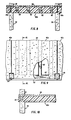
- Fig. 1 illustrates individual panel members by the general designation 22 each of which is provided with a plastic core 24, an optional outer wall mesh member 26 plus an optional inner wall mesh member 28.
- Mesh members 26, 28 may be fixedly secured to each other through the plastic core 24 or hung on the plastic core 24 by suitable hooks, not shown, and are also optionally secured to the I-beam flanges by welding or other means.
- a concrete 29 or plastic 31 or other coating is applied manually or pneumatically to the mesh covered surfaces of the panel as seen in Fig. la. These materials bond firmly to the plastic material and to the mesh, allowing then a structural member of great strength to be formed.
- I-beams are indicated generally at 30 thereby providing a vertical column. These I-beams 30 are preferably regularly spaced along wall section 20.
- the I-beams are secured to a suitable foundation or concrete slab 32 in conventional manner.
- the I-beams themselves include end flange members 34 which separate optional adjacent mesh members 26 from and along the outer wall and adjacent optional mesh members 28 from and along the inner walls. This lifting of the mesh away from the wall places the mesh 26 and 28 in the best position for reinforcing the coatings to be applied to the surfaces.
- a central or interconnecting web member 36 carries the end flange members.
- a horizontally disposed I-beam 38 is affixed to the columnar I-beams 30 in the plane of wall section 20 and on top of a plate member along the upper wall of the wall section.
- the columnar I-beams 30 and the horizontal I-beams 38 may be metallic, but could also be made of fiberglass, concrete, or wood in any combination. Alternately, the I-beams could be replaced by square or rectangular wooden or plastic or metallic building shapes.
- Fig. 3 also illustrates a roof panel member indicated generally at 40.
- Roof panel member 40 is provided with a central plastic core 42, an upper or outer mesh member 44 and an optional lower or inner mesh member 46.
- a truncated optional panel member indicated generally at 48 provides an overhang for the roof.
- the truncated panel member 48 may be provided with an upstanding or elevated end lip member 50 and elevated side lip members 52 with these lip members provided on at least three sides of the roof structure so as to provide restraining means for a layer of concrete which is poured atop the upper surface of the roof panel member 40.
- roof panel member 40 is generally provided with straight sides, it may be tapered as in the roof panel members illustrated in Fig. 5. Thus, it will be seen that the roof panel members may taper inwardly as the panel structure approaches an apex of the roof structure.
- Figs. 4 and 5 illustrate a modified form of the individual panel members and is designated 22a in Fig. 5.
- a reinforced concrete column member is indicated generally at 54 which is in the plane of wall section 20.
- the panel member 22a is provided with a longitudinally extending groove 56 so as to receive reinforced concrete therein.
- the reinforced concrete in groove 56 establishes a perimeter beam for the structure extending around the four sides thereof.
- the pouring of the concrete on an in situ basis is effected prior to placement of the roof panel members 40a, or following placement of the roof panel members 40a, with the aid of a plurality of apertures 58 which provide conduits for the concrete that provides a layer thereof atop the roof panel members designated 40a in Figs. 4 and 5.
- ducts for heating, ventilating and air conditioning located outside the enclosed perimeter of the house, these ducts may be brought into communication with the inside of the house by openings cut through the perimeter walls.
- roof members 48a and intermediate floor panel members 40a may be also provided with longitudinally extending channels 60 to receive reinforced concrete therein.
- the channel 60 is not required, the concrete and the plastic forming a composite beam.
- at least one laterally extending conduit 62 is provided in fluid communication with the longitudinally extending channel means 60, and the columns 54, and is poured together with the extension of the reinforced column 54, joining together the entire structure.
- a laterally extending conduit such as is illustrated at 62 is provided at opposite ends of the roof panel member 40a. While the reinforced conduit itself is not illustrated in Figs. 4 and 5, it is illustrated in Figs. 8 - 10 at 64.
- FIG. 6 illustrates a typical building manufactured in accordance with the present invention. As is illustrated, the invention is applicable to multi-story buildings as well as to single story buildings. This figure illustrates the general relationship between the reinforced concrete column members 54 and the reception of individual panel members 22 therebetween.
- the building illustrates optional tapered rafters 66 with the roof panel members removed for purposes of clarity.
- the tapered rafters are not required for short spans, and, if employed, may be tapered or parallel sided.
- the specific construction for the peak of the building is not critical insofar as the present invention is concerned and may be effected in any conventional manner, with or without a reinforced concrete ridge beam 89.
- FIGs. 11 and 12 there are illustrated two methods of forming the concrete column members 54.
- two molded panel members 22b having top and bottom major surfaces are provided with cooperating corner grooves which extend for the height of the panel members 22b.
- the panel members are abutted so as to align the cooperating corner grooves or notches 68 and the previously installed and anchored reinforcing by vertical rebars 90, and establish at least a major portion of a mold cavity.
- the mold cavity in this instance may be completed by straddling the adjacent grooves of the abutting panel members with a temporary form member 70 to complete the mold cavity, then pouring the concrete into the cavity so as to form a concrete column and permanently establish a portion of a wall with the abutting panel members of the concrete column.
- the cavity formed may be filled with gunite at the same time that surface 22b is concreted over mesh 26, binding the entire structure.
- the panel members 22b may be removed and other panel members supplied.
- cooperating longitudinal grooves 72 are provided in the sides of panel members 22c between the top and bottom major surfaces thereof so as to complete the mold cavity for reception of concrete.
- the cavity will be formed around previously placed and anchored vertical rebars 90, following which the concrete is poured or tremied into the mold cavity. Again it is possible either to leave the panel members 22c in place forming a permanent portion of a wall or to remove the panel members 22c and utilize other panel members.
- the rebar should be previously located so that the mesh can be attached prior to the guniting or plastering of the outer vertical wall sections, thereby joining the entire structure when the column and the vertical wall surfaces are gunited.
- the panel members are not provided with end grooves. Instead the panels are positioned a distance apart equal to the width of the vertical column members and a temporary formwork 70 spans the gap in the rear between the adjacent panels.
- the rebars 90 are placed in position and the mesh in front of the panels is secured to the reinforcing rebars.
- the column member is then formed by guniting through the mesh to fill the cavity. After the reinforced concrete hardens, the temporary form member 70 is removed.
- the reinforced concrete column members 54 illustrated in this figure may be formed by either of the methods illustrated in Figs. 11 and 12 after which the concrete is poured atop the flat roof or intermediate floor panel members 40a at the same time filling the optional longitudinally extending channels 60.
- the laterally extending channel or conduit 62 flowing into the area designated 64a immediately above columns 54 are filled at the same time, firmly joining the conduit 62 to the columns 54.
- Fig. 13 illustrates a core structure 22d for a modular panel member which comprises a heat insulating plastic member 24 which is molded with top and bottom major surfaces and which has a rigid strip member 76 embedded therewithin.
- the rigid strip member 76 is provided with substantially V-shaped corrugations which have ridges substantially coincident with the top major surface of the molded plastic core 24 and troughs which are substantially coincident with the bottom major surface of plastic core 24.
- the rigid strip member 76 may also be provided with a plurality of apertures 77, either randomly or regularly placed.
- rigid strip member 76 While the reinforcement provided by rigid strip member 76 will prevent bending about one axis, in order to prevent bending at 90 degrees thereto, the rigid strip member 76 is provided with slots 78 at a plurality of locations so as to provide parallel lines of slots which then receive a plurality of tension members 80 thereby inhibiting bending about two plans 90 degrees with respect to each other. While the drawing depicts the deposition of a plurality of tension members 80 in the ridges of the rigid strip member 76, it is also possible to provide a similar set of tension members 80 in the troughs of the rigid strip member 76. Tension members may be rods, wires, fiberglass, or plastic.
- Fig. 14 illustrates another core structure for a modular panel member designated 22e.
- a heat insulating plastic member 24 is molded with parallel top and bottom major surfaces and a honeycomb member indicated generally at 82 is embedded therewithin.
- the honeycomb member 82 has cell members which extend between the top and bottom major surfaces of the heat insulating plastic member 24 and an optional frame means 84 may extend around the sides and ends of the core structure, or may be placed within the perimeter of the plastic core rectangle, thereby forming framed openings for doors and windows.
- Figs. 15 and 16 illustrate two preferred building panels for roof structures.
- a core construction of styrofoam or similar core material is illustrated at 24 and a thin layer of reinforced concrete 64 is applied atop the styrofoam core.
- a relatively thin tensile member is secured to the bottom of the styrofoam core.
- the relatively thin tensile member is a metal mesh member 46 and in the figure 16 embodiment, the relatively thin tensile member is fiberglass.
- the tensile members may be then covered with plaster or concrete, forming a composite beam type structure.
- the panel members of the present invention permit all openings to be either cast in or cut in either before or after the covering operations. Provisions may be made for air conditioning and other duct work including electrical conduit raceways or other devices for inserting electrical cables or the like.
- the panels may also be ducted for water and sewer connection.
- composite structure are employed in many different ways in the construction process.
- the foregoing deals with a non-conventional application of construction materials, and in particular with the utilization of expanded polystyrene (or polyurethane or similar), which serves not only as a formwork to receive a deck or wall or roof slab, but also serves to cooperate with a concrete or reinforced concrete slab to resist externally applied loads.
- expanded polystyrene or polyurethane or similar
- the same expanded plastic foam couplies as an insulating thermal material of superior quality.
- the material when joined to a reinforced concrete slab which absorbs compressive forces assists in achieving longer spans than would be the case without the foam.
- the factor n will allow much longer clear spans than would be the case without the plastic over which the slab is poured.
- the tension member could be a steel or plastic mesh located at the bottom of the plastic section, or could be metal, fiberglass, or similar strands applied to the bottom of the plastic, as long as a firm adherance is achieved.
Landscapes
- Engineering & Computer Science (AREA)
- Architecture (AREA)
- Physics & Mathematics (AREA)
- Electromagnetism (AREA)
- Civil Engineering (AREA)
- Structural Engineering (AREA)
- Building Environments (AREA)
- Curing Cements, Concrete, And Artificial Stone (AREA)
- Panels For Use In Building Construction (AREA)
Priority Applications (1)
| Application Number | Priority Date | Filing Date | Title |
|---|---|---|---|
| AT86305235T ATE62722T1 (de) | 1985-07-05 | 1986-07-07 | Gebaeudekonstruktionen aus bewehrtem beton. |
Applications Claiming Priority (2)
| Application Number | Priority Date | Filing Date | Title |
|---|---|---|---|
| US06/751,808 US4625484A (en) | 1985-07-05 | 1985-07-05 | Structural systems and components |
| US751808 | 1985-07-05 |
Publications (2)
| Publication Number | Publication Date |
|---|---|
| EP0208529A1 true EP0208529A1 (de) | 1987-01-14 |
| EP0208529B1 EP0208529B1 (de) | 1991-04-17 |
Family
ID=25023569
Family Applications (1)
| Application Number | Title | Priority Date | Filing Date |
|---|---|---|---|
| EP86305235A Expired - Lifetime EP0208529B1 (de) | 1985-07-05 | 1986-07-07 | Gebäudekonstruktionen aus bewehrtem Beton |
Country Status (5)
| Country | Link |
|---|---|
| US (1) | US4625484A (de) |
| EP (1) | EP0208529B1 (de) |
| AT (1) | ATE62722T1 (de) |
| CA (1) | CA1276422C (de) |
| DE (1) | DE3678759D1 (de) |
Cited By (5)
| Publication number | Priority date | Publication date | Assignee | Title |
|---|---|---|---|---|
| CN102505838A (zh) * | 2011-10-26 | 2012-06-20 | 广州市建筑置业有限公司 | 一种多功能大体积混凝土模板的构筑方法 |
| CN106320601A (zh) * | 2016-08-22 | 2017-01-11 | 沈阳建筑大学 | 装配式混凝土整体无热桥板墙及其竖向连接方法 |
| CN107587630A (zh) * | 2017-09-05 | 2018-01-16 | 山东绿昱建筑科技有限公司 | 一种轻骨料隔墙及其与主体同时施工工艺 |
| CN110886407A (zh) * | 2019-12-15 | 2020-03-17 | 张影 | 一种适用于钢结构建筑的民居隔音保温结构 |
| CN112012475A (zh) * | 2020-07-31 | 2020-12-01 | 唐山华纤无机纤维研究院有限公司 | 一种建筑用免拆模板及制造方法 |
Families Citing this family (50)
| Publication number | Priority date | Publication date | Assignee | Title |
|---|---|---|---|---|
| DE3610030C1 (de) * | 1986-03-25 | 1987-02-05 | Rapp Albert Bruno | Bauelement fuer Hochbauwerke |
| FR2614051B1 (fr) * | 1987-04-16 | 1991-09-20 | Thouraud Sa | Structure modulaire en beton arme pour la construction de logements |
| US4841702A (en) * | 1988-02-22 | 1989-06-27 | Huettemann Erik W | Insulated concrete building panels and method of making the same |
| US4942707A (en) * | 1988-02-22 | 1990-07-24 | Huettemann Erik W | Load-bearing roof or ceiling assembly made up of insulated concrete panels |
| ES2007798A6 (es) * | 1988-03-17 | 1989-07-01 | Gonzalez Espinosa De Los Monte | Sistema de construccion de viviendas y edificaciones mediante componentes prefabricados. |
| US5371990A (en) * | 1992-08-11 | 1994-12-13 | Salahuddin; Fareed-M. | Element based foam and concrete modular wall construction and method and apparatus therefor |
| US5404685A (en) * | 1992-08-31 | 1995-04-11 | Collins; Dennis W. | Polystyrene foamed plastic wall apparatus and method of construction |
| ATE202609T1 (de) * | 1993-12-20 | 2001-07-15 | R A R Consultants Ltd | Erdbeben-, wind- und feuerwiderstandsfähige vorgefertigte baupaneele und damit geformte strukturen |
| US7353642B1 (en) * | 1995-07-17 | 2008-04-08 | Jose Luis Henriquez | Concrete slab system with self-supported insulation |
| US5737895A (en) * | 1995-12-20 | 1998-04-14 | Perrin; Arthur | Prefabricated construction panels and modules for multistory buildings and method for their use |
| US5867964A (en) * | 1995-12-20 | 1999-02-09 | Perrin; Arthur | Prefabricated construction panels and modules for multistory buildings and method for their use |
| US5921046A (en) * | 1997-04-04 | 1999-07-13 | Recobond, Inc. | Prefabricated building system for walls, roofs, and floors using a foam core building panel and connectors |
| US7254925B2 (en) * | 1999-02-09 | 2007-08-14 | Efficient Building Systems, L.L.C. | Insulated wall assembly |
| US6622452B2 (en) | 1999-02-09 | 2003-09-23 | Energy Efficient Wall Systems, L.L.C. | Insulated concrete wall construction method and apparatus |
| US7083515B2 (en) * | 1999-09-07 | 2006-08-01 | Speedfam-Ipec Corporation | Clean room facility and construction method |
| US6426066B1 (en) * | 2000-01-12 | 2002-07-30 | California Pacific Labs, Inc. | Use of physiologically balanced, ionized, acidic solution in wound healing |
| ECSP014123A (es) * | 2001-07-17 | 2003-03-10 | Bcg Internat Ltd | Sistema de construccion con paneles prefabricados de estructura metalica (murotec) |
| EP1342553B1 (de) * | 2002-03-08 | 2016-05-18 | Airbus Operations GmbH | Verfahren zum Herstellen eines Fensterrahmens für Flugzeuge aus faserverstärktem Kunststoff und Vorrichtung zur Durchführung des Verfahrens |
| US6735914B2 (en) * | 2002-07-03 | 2004-05-18 | Peter J. Konopka | Load bearing wall |
| US6920729B2 (en) * | 2002-07-03 | 2005-07-26 | Peter J. Konopka | Composite wall tie |
| US20040006516A1 (en) * | 2002-07-05 | 2004-01-08 | Anjali Anagol-Subbarao | Architecture and method for order placement web service |
| US20040111989A1 (en) * | 2002-12-13 | 2004-06-17 | Housing Technology, Inc. | Method for interlocking molded building panels |
| EA007513B1 (ru) | 2003-04-07 | 2006-10-27 | ЛАЙФ ШИЛД ИНДЖИНИИРД СИСТЕМЗ, ЭлЭлСи | Система для сдерживания распространения шрапнели и способ её производства |
| US20040231264A1 (en) * | 2003-05-23 | 2004-11-25 | Littleton Earl Raymond | Simple handle |
| US20050055918A1 (en) * | 2003-08-14 | 2005-03-17 | York International Corporation | Roof panel construction for an air handling unit |
| ITMI20041326A1 (it) * | 2004-07-01 | 2004-10-01 | Pigazzi Reti S R L | Sistema di elementi elettrosaldati per l'armatura dei pannelli prefabbricati |
| US7357394B2 (en) * | 2004-10-01 | 2008-04-15 | Sri Acquisition Corp. | Modular shooting range |
| EA200700999A1 (ru) | 2004-11-02 | 2008-04-28 | ЛАЙФ ШИЛД ИНДЖИНИИРД СИСТЕМЗ, ЭлЭлСи | Системы для удерживания осколков и пуль (снарядов) и способы их получения |
| WO2007073363A2 (en) | 2004-12-01 | 2007-06-28 | Life Shield Engineered Systems, Llc | Shrapnel and projectile containment systems and equipment and methods for producing same |
| US20080008538A1 (en) * | 2005-05-05 | 2008-01-10 | Timdil, Inc. | Foundation system |
| CN100575644C (zh) * | 2005-12-29 | 2009-12-30 | 陈林 | 标准化城市产品 |
| US7967296B1 (en) | 2006-03-14 | 2011-06-28 | Sri Aquisition Corp. | Modular shooting system |
| CA2675206A1 (en) * | 2007-01-12 | 2008-07-24 | The Nordam Group, Inc. | Composite aircraft window frame |
| US8039102B1 (en) | 2007-01-16 | 2011-10-18 | Berry Plastics Corporation | Reinforced film for blast resistance protection |
| US9665543B2 (en) * | 2007-03-21 | 2017-05-30 | International Business Machines Corporation | System and method for reference validation in word processor documents |
| US7905062B2 (en) * | 2008-12-10 | 2011-03-15 | Stephen Llewellyn Simons | Perfect perch roofing system |
| DE102009011616A1 (de) * | 2009-03-04 | 2010-09-09 | Schöck Bauteile GmbH | Schalungsvorrichtung und Verfahren zum Schaffen einer Aussparung beim Gießen eines Bauteils |
| US8590242B1 (en) * | 2009-03-04 | 2013-11-26 | Thomas J. Ogorchock | Insulated concrete wall |
| US8572900B1 (en) | 2010-01-22 | 2013-11-05 | Epic Metals Corporation | Decking having a removable rib |
| AU2011282468A1 (en) * | 2010-07-21 | 2013-01-10 | Formcraft Pty Ltd | An insulating form |
| US20130097956A1 (en) * | 2011-04-21 | 2013-04-25 | John Joseph Francavilla | Composite Concrete and Framing System and Method for Building Construction |
| US9790406B2 (en) | 2011-10-17 | 2017-10-17 | Berry Plastics Corporation | Impact-resistant film |
| CN104641055A (zh) * | 2012-06-29 | 2015-05-20 | 沃尔夫冈·阿道夫·宾德 | 建造系统及方法 |
| CN103821366B (zh) * | 2014-03-03 | 2016-02-10 | 永升建设集团有限公司 | 清水砼墙面槽型立体木纹装饰施工方法 |
| US9738009B2 (en) | 2014-04-30 | 2017-08-22 | Bautex Systems, LLC | Methods and systems for the formation and use of reduced weight building blocks forms |
| CN107447925B (zh) * | 2016-02-24 | 2019-07-05 | 衢州市联橙环保科技有限公司 | 一种隔热隔音木屋屋顶 |
| CN109707049A (zh) * | 2019-02-21 | 2019-05-03 | 四川建安装配式工程科技股份有限公司 | 保温隔音墙板以及装配式建筑主体结构 |
| US20210324629A1 (en) * | 2019-10-07 | 2021-10-21 | Elisha Halsey Brinton | Unified Prefinished Panel |
| JP7678941B2 (ja) | 2021-08-12 | 2025-05-16 | プランク ストラクチュアル システムズ エルエルシー | 積層された補強体を伴う発泡体が充填された構造厚板建築物基礎 |
| US20250237056A1 (en) * | 2024-01-19 | 2025-07-24 | Mikhail Topr | Wall panel with window aperture |
Citations (5)
| Publication number | Priority date | Publication date | Assignee | Title |
|---|---|---|---|---|
| FR2153288A1 (de) * | 1971-09-20 | 1973-05-04 | Co Data Corp | |
| FR2349692A1 (fr) * | 1976-04-28 | 1977-11-25 | Dso Promishleno Str | Systeme combine de construction, procede et dispositif pour sa mise en oeuvre |
| DE2914920A1 (de) * | 1978-04-19 | 1979-10-31 | Kurt Ing Beranek | Fertigwandteil aus leichtbeton |
| CH625297A5 (en) * | 1977-08-22 | 1981-09-15 | Lc Housing Corp Ag | Set of structural elements for a building |
| GB2093882A (en) * | 1981-03-04 | 1982-09-08 | Milh Alfred Henri | Prefabricated frame and a multi-storey building including said frame |
Family Cites Families (37)
| Publication number | Priority date | Publication date | Assignee | Title |
|---|---|---|---|---|
| US2851873A (en) * | 1949-09-02 | 1958-09-16 | Wheeler-Nicholson Malcolm | Building construction |
| US2744042A (en) * | 1951-06-21 | 1956-05-01 | Goodyear Tire & Rubber | Laminated panels |
| US3315424A (en) * | 1963-09-20 | 1967-04-25 | Eugene S Smith | Building construction |
| US3310917A (en) * | 1964-04-13 | 1967-03-28 | Sam A Simon | Building construction and modular panels therefor |
| US3446692A (en) * | 1964-06-01 | 1969-05-27 | Pullman Inc | Insulated panel and method of making same |
| US3398491A (en) * | 1965-05-13 | 1968-08-27 | Henry N. Babcock | Building construction and method |
| US3458609A (en) * | 1966-01-06 | 1969-07-29 | Dow Chemical Co | Method and apparatus for preparing foamed plastic slabs |
| US3803788A (en) * | 1968-06-19 | 1974-04-16 | P Artmann | Building construction and process for producing structural elements for such construction |
| US3677874A (en) * | 1970-03-24 | 1972-07-18 | Grace W R & Co | Insulation product and method |
| US3879908A (en) * | 1971-11-29 | 1975-04-29 | Victor P Weismann | Modular building panel |
| LU70690A1 (de) * | 1973-08-30 | 1974-12-10 | ||
| US4090340A (en) * | 1973-08-30 | 1978-05-23 | Otto Alfred Becker | Load bearing structural element |
| US3874139A (en) * | 1973-11-30 | 1975-04-01 | Edmund A Landwoski | Basement wall construction |
| US4006570A (en) * | 1974-04-01 | 1977-02-08 | Stolz Owen M | Wall structure and manufacturing method therefor |
| US4047357A (en) * | 1974-09-03 | 1977-09-13 | Mulholland Stanley C | Roof structure of concrete edge-to-edge abutting panels and method of interconnecting same |
| US4038798A (en) * | 1975-03-05 | 1977-08-02 | U-Forms International, Inc. | Composite permanent block-form for reinforced concrete construction and method of making same |
| DE2551905A1 (de) * | 1975-11-19 | 1977-08-25 | Hunter Douglas Ind Bv | Vorgefertigtes wandelement |
| BE885564Q (fr) * | 1976-01-05 | 1981-02-02 | Cs & M Inc | Treillis de fil metallique et appareil pour sa fabrication |
| NL7607840A (nl) * | 1976-07-15 | 1978-01-17 | Tolsma Auke | Werkwijze ter vervaardiging van thermisch geiso- leerde gebouwen, voor toepassing bij deze werk- wijze geschikte bouwconstructie-elementen, alsme- de werkwijze ter vervaardiging van de bouwconstruc- tie-elementen. |
| US4071984A (en) * | 1976-09-16 | 1978-02-07 | Kenneth Larrow | House assembly with prefabricated elements |
| US4486993A (en) * | 1977-04-08 | 1984-12-11 | Solarcrete Corporation | Building structure and method of construction |
| US4297820A (en) * | 1977-12-05 | 1981-11-03 | Covington Brothers Technologies | Composite structural panel with multilayered reflective core |
| US4226067A (en) * | 1977-12-05 | 1980-10-07 | Covington Brothers Building Systems, Inc. | Structural panel |
| US4340802A (en) * | 1977-12-05 | 1982-07-20 | Covington Brothers Technologies | Method and apparatus for welding |
| US4336676A (en) * | 1977-12-05 | 1982-06-29 | Covington Brothers, Inc. | Composite structural panel with offset core |
| US4236361A (en) * | 1978-06-12 | 1980-12-02 | Joseph Boden | Prefabricated building components |
| US4250670A (en) * | 1978-11-30 | 1981-02-17 | Larry Garner | Method and article for use in building construction |
| US4288962A (en) * | 1979-02-27 | 1981-09-15 | Kavanaugh Harvey H | Method of forming structural walls and roofs |
| US4249354A (en) * | 1979-03-05 | 1981-02-10 | Wynn Gayle B | Reinforced insulated wall construction |
| US4253288A (en) * | 1979-07-13 | 1981-03-03 | Chun Joo H | Prefabricated wall panel |
| US4342180A (en) * | 1980-02-11 | 1982-08-03 | Gibco International Corporation | Assembly method of constructing a building |
| IT1131699B (it) * | 1980-07-16 | 1986-06-25 | Franco Nania | Elemento di costruzione prefabbricato e costruzione edile realizzata con l'impiego di una pluralita' di tali elementi |
| US4393636A (en) * | 1980-09-24 | 1983-07-19 | Rockstead Raymond H | Box beam reinforced concrete structure |
| US4454702A (en) * | 1981-03-24 | 1984-06-19 | Bonilla Lugo Juan | Building construction and method of constructing same |
| US4489530A (en) * | 1981-12-23 | 1984-12-25 | Chi Ming Chang | Sandwich wall structure and the method for constructing the same |
| US4486996A (en) * | 1982-05-19 | 1984-12-11 | Luis Alejos | Construction-panel prefabrication method, panels thus made and equipment for implementing said method |
| US4505019A (en) * | 1983-03-02 | 1985-03-19 | Deinzer Dietrich F | Method of forming construction panel |
-
1985
- 1985-07-05 US US06/751,808 patent/US4625484A/en not_active Expired - Fee Related
-
1986
- 1986-06-18 CA CA000511809A patent/CA1276422C/en not_active Expired - Lifetime
- 1986-07-07 AT AT86305235T patent/ATE62722T1/de not_active IP Right Cessation
- 1986-07-07 EP EP86305235A patent/EP0208529B1/de not_active Expired - Lifetime
- 1986-07-07 DE DE8686305235T patent/DE3678759D1/de not_active Expired - Fee Related
Patent Citations (5)
| Publication number | Priority date | Publication date | Assignee | Title |
|---|---|---|---|---|
| FR2153288A1 (de) * | 1971-09-20 | 1973-05-04 | Co Data Corp | |
| FR2349692A1 (fr) * | 1976-04-28 | 1977-11-25 | Dso Promishleno Str | Systeme combine de construction, procede et dispositif pour sa mise en oeuvre |
| CH625297A5 (en) * | 1977-08-22 | 1981-09-15 | Lc Housing Corp Ag | Set of structural elements for a building |
| DE2914920A1 (de) * | 1978-04-19 | 1979-10-31 | Kurt Ing Beranek | Fertigwandteil aus leichtbeton |
| GB2093882A (en) * | 1981-03-04 | 1982-09-08 | Milh Alfred Henri | Prefabricated frame and a multi-storey building including said frame |
Cited By (8)
| Publication number | Priority date | Publication date | Assignee | Title |
|---|---|---|---|---|
| CN102505838A (zh) * | 2011-10-26 | 2012-06-20 | 广州市建筑置业有限公司 | 一种多功能大体积混凝土模板的构筑方法 |
| CN102505838B (zh) * | 2011-10-26 | 2014-06-04 | 广州市建筑置业有限公司 | 一种多功能大体积混凝土模板的构筑方法 |
| CN106320601A (zh) * | 2016-08-22 | 2017-01-11 | 沈阳建筑大学 | 装配式混凝土整体无热桥板墙及其竖向连接方法 |
| CN106320601B (zh) * | 2016-08-22 | 2018-11-02 | 沈阳建筑大学 | 装配式混凝土整体无热桥板墙及其竖向连接方法 |
| CN107587630A (zh) * | 2017-09-05 | 2018-01-16 | 山东绿昱建筑科技有限公司 | 一种轻骨料隔墙及其与主体同时施工工艺 |
| CN110886407A (zh) * | 2019-12-15 | 2020-03-17 | 张影 | 一种适用于钢结构建筑的民居隔音保温结构 |
| CN112012475A (zh) * | 2020-07-31 | 2020-12-01 | 唐山华纤无机纤维研究院有限公司 | 一种建筑用免拆模板及制造方法 |
| CN112012475B (zh) * | 2020-07-31 | 2022-05-10 | 唐山华纤无机纤维研究院有限公司 | 一种建筑用免拆模板及制造方法 |
Also Published As
| Publication number | Publication date |
|---|---|
| ATE62722T1 (de) | 1991-05-15 |
| DE3678759D1 (de) | 1991-05-23 |
| CA1276422C (en) | 1990-11-20 |
| EP0208529B1 (de) | 1991-04-17 |
| US4625484A (en) | 1986-12-02 |
Similar Documents
| Publication | Publication Date | Title |
|---|---|---|
| US4625484A (en) | Structural systems and components | |
| US7958687B2 (en) | Concrete panel construction system | |
| US4942707A (en) | Load-bearing roof or ceiling assembly made up of insulated concrete panels | |
| US5526625A (en) | Building panel and buildings using the panel | |
| US4454702A (en) | Building construction and method of constructing same | |
| US6363674B1 (en) | Premanufactured structural building panels | |
| US4669240A (en) | Precast reinforced concrete wall panels and method of erecting same | |
| US5285607A (en) | Building exterior wall panel | |
| US5617686A (en) | Insulating polymer wall panels | |
| US5799453A (en) | Structure and method of fabrication | |
| EP1007799B1 (de) | Bauplatte zur Herstellung von Gebäuden | |
| US4841707A (en) | Composite double or multiple wall | |
| US20050115185A1 (en) | Masonry block constructions with polymeric coating | |
| US20060096236A1 (en) | Structural wall apparatuses, systems, and methods | |
| EP4481129A1 (de) | Vorgefertigtes baukit, verfahren zur herstellung dieses kits und verfahren zur konstruktion eines gebäudes mit diesem baukit | |
| US3874134A (en) | Modular building units | |
| EP4488464A1 (de) | Geschichtetes bauelement, gebäudeteil und gebäude daraus sowie verfahren zur herstellung eines derartigen bauelements, gebäudeteil und gebäude | |
| JPH08232380A (ja) | 鋼製部材と鉄筋コンクリートの結合部材、該結合部材を用いたモノコック構造用パネル及び該パネルを用いたモノコック構造建築物 | |
| KR19980058502U (ko) | 하프pc 콘크리트 슬라브판넬 | |
| JPS6360337A (ja) | 建物の屋根、壁および中間床の完全な構造 | |
| CN86107290A (zh) | 加筋混凝土建筑结构 | |
| EP1185748B1 (de) | Konstruktionssystem aus betonpaneelen | |
| CA2412174A1 (en) | Modular building apparatus and method | |
| JPH04144B2 (de) | ||
| AU2002256579B2 (en) | Masonry block constructions with polymeric coating |
Legal Events
| Date | Code | Title | Description |
|---|---|---|---|
| PUAI | Public reference made under article 153(3) epc to a published international application that has entered the european phase |
Free format text: ORIGINAL CODE: 0009012 |
|
| AK | Designated contracting states |
Kind code of ref document: A1 Designated state(s): AT BE CH DE FR GB IT LI LU NL SE |
|
| 17P | Request for examination filed |
Effective date: 19870713 |
|
| 17Q | First examination report despatched |
Effective date: 19881117 |
|
| GRAA | (expected) grant |
Free format text: ORIGINAL CODE: 0009210 |
|
| AK | Designated contracting states |
Kind code of ref document: B1 Designated state(s): AT BE CH DE FR GB IT LI LU NL SE |
|
| PG25 | Lapsed in a contracting state [announced via postgrant information from national office to epo] |
Ref country code: IT Free format text: LAPSE BECAUSE OF FAILURE TO SUBMIT A TRANSLATION OF THE DESCRIPTION OR TO PAY THE FEE WITHIN THE PRE;WARNING: LAPSES OF ITALIAN PATENTS WITH EFFECTIVE DATE BEFORE 2007 MAY HAVE OCCURRED AT ANY TIME BEFORE 2007. THE CORRECT EFFECTIVE DATE MAY BE DIFFERENT FROM THE ONE RECORDED.SCRIBED TIME-LIMIT Effective date: 19910417 Ref country code: SE Effective date: 19910417 Ref country code: NL Effective date: 19910417 Ref country code: AT Effective date: 19910417 Ref country code: BE Effective date: 19910417 Ref country code: FR Effective date: 19910417 |
|
| REF | Corresponds to: |
Ref document number: 62722 Country of ref document: AT Date of ref document: 19910515 Kind code of ref document: T |
|
| REF | Corresponds to: |
Ref document number: 3678759 Country of ref document: DE Date of ref document: 19910523 |
|
| PG25 | Lapsed in a contracting state [announced via postgrant information from national office to epo] |
Ref country code: GB Effective date: 19910717 |
|
| PG25 | Lapsed in a contracting state [announced via postgrant information from national office to epo] |
Ref country code: LU Free format text: LAPSE BECAUSE OF NON-PAYMENT OF DUE FEES Effective date: 19910731 Ref country code: CH Effective date: 19910731 Ref country code: LI Effective date: 19910731 |
|
| EN | Fr: translation not filed | ||
| NLV1 | Nl: lapsed or annulled due to failure to fulfill the requirements of art. 29p and 29m of the patents act | ||
| PLBE | No opposition filed within time limit |
Free format text: ORIGINAL CODE: 0009261 |
|
| STAA | Information on the status of an ep patent application or granted ep patent |
Free format text: STATUS: NO OPPOSITION FILED WITHIN TIME LIMIT |
|
| GBPC | Gb: european patent ceased through non-payment of renewal fee | ||
| REG | Reference to a national code |
Ref country code: CH Ref legal event code: PL |
|
| PG25 | Lapsed in a contracting state [announced via postgrant information from national office to epo] |
Ref country code: DE Effective date: 19920401 |
|
| 26N | No opposition filed |