EP0208532A2 - Vorrichtung zur Entnahme von Kernproben - Google Patents
Vorrichtung zur Entnahme von Kernproben Download PDFInfo
- Publication number
- EP0208532A2 EP0208532A2 EP86305251A EP86305251A EP0208532A2 EP 0208532 A2 EP0208532 A2 EP 0208532A2 EP 86305251 A EP86305251 A EP 86305251A EP 86305251 A EP86305251 A EP 86305251A EP 0208532 A2 EP0208532 A2 EP 0208532A2
- Authority
- EP
- European Patent Office
- Prior art keywords
- tube
- core sampling
- drill bit
- sampling tube
- segments
- Prior art date
- Legal status (The legal status is an assumption and is not a legal conclusion. Google has not performed a legal analysis and makes no representation as to the accuracy of the status listed.)
- Withdrawn
Links
Images

Classifications
-
- E—FIXED CONSTRUCTIONS
- E21—EARTH OR ROCK DRILLING; MINING
- E21B—EARTH OR ROCK DRILLING; OBTAINING OIL, GAS, WATER, SOLUBLE OR MELTABLE MATERIALS OR A SLURRY OF MINERALS FROM WELLS
- E21B25/00—Apparatus for obtaining or removing undisturbed cores, e.g. core barrels or core extractors
- E21B25/02—Apparatus for obtaining or removing undisturbed cores, e.g. core barrels or core extractors the core receiver being insertable into, or removable from, the borehole without withdrawing the drilling pipe
- E21B25/04—Apparatus for obtaining or removing undisturbed cores, e.g. core barrels or core extractors the core receiver being insertable into, or removable from, the borehole without withdrawing the drilling pipe the core receiver having a core forming cutting edge or element, e.g. punch type core barrels
-
- E—FIXED CONSTRUCTIONS
- E21—EARTH OR ROCK DRILLING; MINING
- E21B—EARTH OR ROCK DRILLING; OBTAINING OIL, GAS, WATER, SOLUBLE OR MELTABLE MATERIALS OR A SLURRY OF MINERALS FROM WELLS
- E21B10/00—Drill bits
- E21B10/64—Drill bits characterised by the whole or part thereof being insertable into or removable from the borehole without withdrawing the drilling pipe
- E21B10/66—Drill bits characterised by the whole or part thereof being insertable into or removable from the borehole without withdrawing the drilling pipe the cutting element movable through the drilling pipe and laterally shiftable
Definitions
- the present invention relates to a core sampling device, in particular a drill bit and core barrel assembly for a wire-line drilling method of obtaining core samples.
- the drill bit comprises effectively an annular cutting device which cuts an annular or cylindrical hole. This hole defines a core which is captured within a core barrel for sampling.
- Devices of this kind suffer the disadvantage that it is not possible to change the drill bit e.g. to accommodate changes in geological conditions or simply to replace a worn bit, without withdrawing the entire drill line.
- a core sampling device comprising a drill bit assembly, a drive shoe arranged to house the drill bit, and a core sampling tube;
- the drill bit assembly including a bit housing, which is drivingly engaged by the drive shoe, and a series of drill segments which are pivotally attached to the housing to be capable of pivoting between a drilling position in which the outer and inner radial limits of the segments define the outer and inner diameters of an annular hole to be drilled, and a retracted position in which the segments are entirely within the diameter of the drive shoe; the segments being maintained in the drilling position by the core sampling tube when this is in a forward position, and the segments being allowed to adopt the retracted position when the sampling tube is withdrawn; the core sampling tube engaging the drill bit assembly whereby continued withdrawal of the core sampling tube causes withdrawal of the drill bit assembly from within the drive shoe.
- the bit can be removed together with the core, without having to withdraw the entire drill line.
- the device includes a retraction tube which is connected to the drill bit housing and which is engaged by the core sampling tube on its withdrawal in order to withdraw the drill bit assembly.
- the core sampling tube houses a core spring.
- the drive shoe has a screw thread for connection to an outer tube of a drill line and the core sampling tube has connecting means for connection to an inner tube of a drill line.
- the said connecting means provides a connection allowing a limited rocking movement between the core sampling tube and the inner tube.
- the preferred construction may ensure correct movement of the bit segments into their correct mode. It will also provide a sufficient degree of freedom to accommodate the core without damaging the core, and also allows a considerable flow of lubricant for cooling and the removal of pulverised material.
- the drill line at the bit end is shown schematically as comprising an outer tube 11 and an inner tube 12.
- the sampling device comprises a drive shoe and reaming shell 13, a bit 14, a core spring carrier tube 15 housing a core spring 16, and a perforated retraction tube 17.
- the drive shoe 13 is connected to the outer tube 11 by a screw thread connection 18.
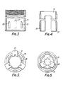
- the bit 14 comprises a bit housing 19 and a series (in this case 3) of hinged cutting segments 21.
- a retaining spring 22 holds the bit elements together.
- the spring carrier 15 is connected to the inner tube 12 via a swivel attachment 23 which is threadably connected to the spring carrier 15 and connected to the inner tube 12.
- the 30carrier tube 15 When the device is in its drilling mode, the 30carrier tube 15 is located in a forward position as shown in FIGURE 1. In this position, the segments 21 are forced to adopt an outwardly extended orientation by the forward portion of the tube 15, so that the radially outer extent of the cutting segments 21 define the outer diameter of the annular hole which is to be cut, while the radially inner extent of the segments 21 define the inner diameter of the annular hole.
- the drive to the bit is supplied by the outer tube 11 which drives the drive shoe 13 which in turn drives the bit housing 19 through driving keys 25 which co- operate with corresponding keys 26 in the bit housing.
- These components rotate relative to the inner tube 12 10and carrier tube 15.
- the shoe 13 also has an appropriate number of guides 27 in the form of fixed or free balls which guide the segments 21 into the correct position for drilling.
- the drill bit 14 can be changed if required without the necessity of removing the entire drill line.
- the bit can have a cutting faces (kerf) which are surface-set with diamonds, or matrix impregnated with diamond grit.
- the cutting medium may be a hard material such as tungsten carbide or indeed the bit 14 can carry pads which are of tungsten carbide faced with diamond grit, as may be appropriate to the geological conditions.
- perforated tube 17 allows continuous fluid throughput, notwithstanding the additional metal elements which are extra over and 20above those which would be used in a wire line barrel without a retractable bit
Landscapes
- Engineering & Computer Science (AREA)
- Geology (AREA)
- Life Sciences & Earth Sciences (AREA)
- Mining & Mineral Resources (AREA)
- Physics & Mathematics (AREA)
- Environmental & Geological Engineering (AREA)
- Fluid Mechanics (AREA)
- General Life Sciences & Earth Sciences (AREA)
- Geochemistry & Mineralogy (AREA)
- Mechanical Engineering (AREA)
- Earth Drilling (AREA)
- Sampling And Sample Adjustment (AREA)
- Processing Of Stones Or Stones Resemblance Materials (AREA)
- Investigation Of Foundation Soil And Reinforcement Of Foundation Soil By Compacting Or Drainage (AREA)
Applications Claiming Priority (2)
| Application Number | Priority Date | Filing Date | Title |
|---|---|---|---|
| GB8517388 | 1985-07-09 | ||
| GB858517388A GB8517388D0 (en) | 1985-02-14 | 1985-07-09 | Retractable wireline core bit/barrel |
Publications (2)
| Publication Number | Publication Date |
|---|---|
| EP0208532A2 true EP0208532A2 (de) | 1987-01-14 |
| EP0208532A3 EP0208532A3 (de) | 1987-10-07 |
Family
ID=10582054
Family Applications (1)
| Application Number | Title | Priority Date | Filing Date |
|---|---|---|---|
| EP86305251A Withdrawn EP0208532A3 (de) | 1985-07-09 | 1986-07-08 | Vorrichtung zur Entnahme von Kernproben |
Country Status (6)
| Country | Link |
|---|---|
| US (1) | US4878549A (de) |
| EP (1) | EP0208532A3 (de) |
| AU (1) | AU5974686A (de) |
| CA (1) | CA1264316A (de) |
| GB (1) | GB2181764B (de) |
| ZA (1) | ZA865010B (de) |
Cited By (7)
| Publication number | Priority date | Publication date | Assignee | Title |
|---|---|---|---|---|
| EP0678654A3 (de) * | 1993-06-16 | 1996-09-11 | Down Hole Tech Pty Ltd | Auswechselbares Schneidmittelsegment für einen Bohrmeissel. |
| AP577A (en) * | 1993-06-16 | 1997-03-26 | Down Hole Tech Pty Limited | System for use in situ replacement of cutting means for a ground drill. |
| US5743344A (en) * | 1995-05-18 | 1998-04-28 | Down Hole Technologies Pty. Ltd. | System for in situ replacement of cutting means for a ground drill |
| WO1998055730A1 (en) * | 1997-06-06 | 1998-12-10 | Dht Technologies Limited | Retrieval head for a drill bit composed of a plurality of bit segments |
| AU740085B2 (en) * | 1997-06-06 | 2001-11-01 | Dht Technologies Limited | Retrieval head for a drill bit composed of a plurality of bit segments |
| RU2204011C2 (ru) * | 1998-11-06 | 2003-05-10 | Всероссийский научно-исследовательский институт методики и техники разведки | Буровой снаряд с вставной коронкой-расширителем |
| CN101881160A (zh) * | 2010-06-25 | 2010-11-10 | 郑州远见矿用设备有限公司 | 定点取样器 |
Families Citing this family (16)
| Publication number | Priority date | Publication date | Assignee | Title |
|---|---|---|---|---|
| US5325931A (en) * | 1993-08-27 | 1994-07-05 | Kennametal Inc. | Chuck assembly for a drill box of a mine drill |
| SE9401349D0 (sv) * | 1994-04-21 | 1994-04-21 | Atlas Copco Rocktech Ab | Foderrör med slagsko |
| AU124096S (en) | 1994-12-07 | 1995-07-14 | Down Hole Tech Pty Ltd | Drill bit finger |
| AU124522S (en) | 1994-12-15 | 1995-08-31 | Down Hole Tech Pty Ltd | Drill bit finger |
| AU125162S (en) | 1995-02-21 | 1995-11-13 | Down Hole Tech Pty Ltd | Cutting head |
| US6428245B1 (en) | 2000-01-12 | 2002-08-06 | Nashcliffe Geochemicals Ltd. | Method of and apparatus for transporting particulate materials from a lower level to a higher level |
| AUPP683898A0 (en) * | 1998-10-29 | 1998-11-26 | Dht Technologies Limited | Retractable drill bit system |
| US8025107B2 (en) * | 2008-05-15 | 2011-09-27 | Longyear Tm, Inc. | Reamer with polycrystalline diamond compact inserts |
| CN102102498B (zh) * | 2010-11-26 | 2013-05-22 | 浙江大学 | 软岩层钻探专用的绳索取芯系统及其使用方法 |
| CA2857841C (en) | 2013-07-26 | 2018-03-13 | National Oilwell DHT, L.P. | Downhole activation assembly with sleeve valve and method of using same |
| US9494004B2 (en) | 2013-12-20 | 2016-11-15 | National Oilwell Varco, L.P. | Adjustable coring assembly and method of using same |
| US10107055B2 (en) * | 2016-09-01 | 2018-10-23 | Baker Hughes, A Ge Company, Llc | Core catcher |
| CN106761512B (zh) * | 2016-12-28 | 2023-03-24 | 深圳市盛业地下工程有限公司 | 岩心切割装置及施工方法 |
| WO2019068145A1 (en) | 2017-10-03 | 2019-04-11 | Reflex Instruments Asia Pacific Pty Ltd | SYSTEM FOR ESTABLISHING A DOWNHILL DEVICE AND RELATED DRIVE TRANSFER AND METHOD FOR PROVIDING A DEVICE AT THE BACKGROUND OF A HOLE |
| CN109281627B (zh) * | 2018-08-13 | 2024-02-20 | 中国地质科学院勘探技术研究所 | 一种多节铰链式防顶死弹卡定位机构 |
| CN110805404A (zh) * | 2019-12-10 | 2020-02-18 | 中煤地第二勘探局集团有限责任公司 | 一种爪簧式双管取样钻具 |
Family Cites Families (15)
| Publication number | Priority date | Publication date | Assignee | Title |
|---|---|---|---|---|
| FR366316A (fr) * | 1906-05-17 | 1906-10-02 | Michel Boof | Machine à forer et extensible pour l'obtention de toute masse centrale |
| US1162441A (en) * | 1914-09-14 | 1915-11-30 | William D Hamer | Drill. |
| US1502463A (en) * | 1922-12-26 | 1924-07-22 | George W Dunsworth | Drill bit |
| US1996132A (en) * | 1932-05-11 | 1935-04-02 | Clinton L Walker | Deep well drilling and coring system |
| US2842343A (en) * | 1954-11-19 | 1958-07-08 | Walter L Church | Retractible bit |
| US2850265A (en) * | 1956-02-08 | 1958-09-02 | Ellery M Cruthers | Core extractor for core drill |
| US3603413A (en) * | 1969-10-03 | 1971-09-07 | Christensen Diamond Prod Co | Retractable drill bits |
| US3603411A (en) * | 1970-01-19 | 1971-09-07 | Christensen Diamond Prod Co | Retractable drill bits |
| US3692126A (en) * | 1971-01-29 | 1972-09-19 | Frank C Rushing | Retractable drill bit apparatus |
| SU579403A1 (ru) * | 1974-10-01 | 1977-11-05 | Всесоюзный Научно-Исследовательский Институт Методики И Техники Разведки | Вставное долото режущего типа |
| FR2372955A1 (fr) * | 1976-12-01 | 1978-06-30 | Tourba Jean Marie | Couronne de forage retractable |
| SU777198A1 (ru) * | 1977-10-20 | 1980-11-07 | Специальное Конструкторское Бюро Научно-Производственного Объединения "Геотехника" Министерства Геологии Ссср | Раздвижна бурова коронка |
| SU1049653A1 (ru) * | 1982-06-18 | 1983-10-23 | Matveev Yurij A | Буровой снар д |
| SE455326B (sv) * | 1983-02-04 | 1988-07-04 | Komitet Geol | Demonterbar kernborrutrustning |
| US4497382A (en) * | 1983-03-24 | 1985-02-05 | Komitet Po Goelogica | Retractable core drill bit |
-
1986
- 1986-07-04 CA CA000513162A patent/CA1264316A/en not_active Expired - Fee Related
- 1986-07-04 ZA ZA865010A patent/ZA865010B/xx unknown
- 1986-07-04 AU AU59746/86A patent/AU5974686A/en not_active Abandoned
- 1986-07-08 GB GB08616641A patent/GB2181764B/en not_active Expired
- 1986-07-08 EP EP86305251A patent/EP0208532A3/de not_active Withdrawn
-
1988
- 1988-10-12 US US07/256,509 patent/US4878549A/en not_active Expired - Fee Related
Cited By (11)
| Publication number | Priority date | Publication date | Assignee | Title |
|---|---|---|---|---|
| EP0678654A3 (de) * | 1993-06-16 | 1996-09-11 | Down Hole Tech Pty Ltd | Auswechselbares Schneidmittelsegment für einen Bohrmeissel. |
| EP0702746A4 (de) * | 1993-06-16 | 1996-09-11 | Down Hole Tech Pty Ltd | System zum im loch auswechseln von schneidmitteln für einen bohrmeissel |
| EP0678652A3 (de) * | 1993-06-16 | 1996-09-11 | Down Hole Tech Pty Ltd | Einsatz zum Halten von Schneidmitteln in einem Bohrmeissel. |
| AP577A (en) * | 1993-06-16 | 1997-03-26 | Down Hole Tech Pty Limited | System for use in situ replacement of cutting means for a ground drill. |
| US5662182A (en) * | 1993-06-16 | 1997-09-02 | Down Hole Technologies Pty Ltd. | System for in situ replacement of cutting means for a ground drill |
| US5743344A (en) * | 1995-05-18 | 1998-04-28 | Down Hole Technologies Pty. Ltd. | System for in situ replacement of cutting means for a ground drill |
| WO1998055730A1 (en) * | 1997-06-06 | 1998-12-10 | Dht Technologies Limited | Retrieval head for a drill bit composed of a plurality of bit segments |
| US6244363B1 (en) | 1997-06-06 | 2001-06-12 | Dht Technologies, Ltd | Retrieval head for a drill bit composed of a plurality of bit segments |
| AU740085B2 (en) * | 1997-06-06 | 2001-11-01 | Dht Technologies Limited | Retrieval head for a drill bit composed of a plurality of bit segments |
| RU2204011C2 (ru) * | 1998-11-06 | 2003-05-10 | Всероссийский научно-исследовательский институт методики и техники разведки | Буровой снаряд с вставной коронкой-расширителем |
| CN101881160A (zh) * | 2010-06-25 | 2010-11-10 | 郑州远见矿用设备有限公司 | 定点取样器 |
Also Published As
| Publication number | Publication date |
|---|---|
| GB8616641D0 (en) | 1986-08-13 |
| CA1264316A (en) | 1990-01-09 |
| AU5974686A (en) | 1987-01-15 |
| US4878549A (en) | 1989-11-07 |
| EP0208532A3 (de) | 1987-10-07 |
| GB2181764A (en) | 1987-04-29 |
| ZA865010B (en) | 1988-02-24 |
| GB2181764B (en) | 1988-11-09 |
Similar Documents
| Publication | Publication Date | Title |
|---|---|---|
| EP0208532A2 (de) | Vorrichtung zur Entnahme von Kernproben | |
| US4817725A (en) | Oil field cable abrading system | |
| AU2020201994B2 (en) | Rotational drill bits and drilling apparatuses including the same | |
| US6964303B2 (en) | Horizontal directional drilling in wells | |
| US4635738A (en) | Drill bit | |
| USRE32036E (en) | Drill bit | |
| US4323130A (en) | Drill bit | |
| US10392866B2 (en) | Rotational drill bits and apparatuses including the same | |
| US5350015A (en) | Rotary downhole cutting tool | |
| IE46812B1 (en) | Means for drilling | |
| JPS58173287A (ja) | ボ−リング用回転ビツト | |
| US3155179A (en) | Dual-tube drill string for sample drilling | |
| US10907413B1 (en) | Continuous sampling drill bit | |
| US3712392A (en) | Diamond drill assembly with bore hole support | |
| EP0058061A2 (de) | Erdbohrwerkzeug | |
| US4497383A (en) | Undercutting device for anchor holes | |
| EP0347033A2 (de) | Bohrlochräumer | |
| US6021856A (en) | Bit retention system | |
| US4010808A (en) | Expandable raise bit | |
| US2893696A (en) | Rotary, earth trepanning tools | |
| US2549420A (en) | Coring and crushing bit | |
| US4667753A (en) | Core retainer for sidewall core tools | |
| US5103921A (en) | Coring assembly for mounting on the end of a drill string | |
| CN114837566B (zh) | 一种螺旋齿轮牙轮钻头 | |
| US5657827A (en) | Auger drilling head |
Legal Events
| Date | Code | Title | Description |
|---|---|---|---|
| PUAI | Public reference made under article 153(3) epc to a published international application that has entered the european phase |
Free format text: ORIGINAL CODE: 0009012 |
|
| AK | Designated contracting states |
Kind code of ref document: A2 Designated state(s): AT BE CH DE FR GB IT LI LU NL SE |
|
| PUAL | Search report despatched |
Free format text: ORIGINAL CODE: 0009013 |
|
| RHK1 | Main classification (correction) |
Ipc: E21B 25/04 |
|
| AK | Designated contracting states |
Kind code of ref document: A3 Designated state(s): AT BE CH DE FR GB IT LI LU NL SE |
|
| 17P | Request for examination filed |
Effective date: 19880331 |
|
| 17Q | First examination report despatched |
Effective date: 19890421 |
|
| STAA | Information on the status of an ep patent application or granted ep patent |
Free format text: STATUS: THE APPLICATION IS DEEMED TO BE WITHDRAWN |
|
| 18D | Application deemed to be withdrawn |
Effective date: 19920201 |
|
| RIN1 | Information on inventor provided before grant (corrected) |
Inventor name: BENNETT, ANDREW HALL |