EP0209042A2 - Vessel or jug with a removable hinged lid - Google Patents
Vessel or jug with a removable hinged lid Download PDFInfo
- Publication number
- EP0209042A2 EP0209042A2 EP86109273A EP86109273A EP0209042A2 EP 0209042 A2 EP0209042 A2 EP 0209042A2 EP 86109273 A EP86109273 A EP 86109273A EP 86109273 A EP86109273 A EP 86109273A EP 0209042 A2 EP0209042 A2 EP 0209042A2
- Authority
- EP
- European Patent Office
- Prior art keywords
- housing
- holding member
- vessel
- opening
- cover
- Prior art date
- Legal status (The legal status is an assumption and is not a legal conclusion. Google has not performed a legal analysis and makes no representation as to the accuracy of the status listed.)
- Withdrawn
Links
Images

Classifications
-
- B—PERFORMING OPERATIONS; TRANSPORTING
- B65—CONVEYING; PACKING; STORING; HANDLING THIN OR FILAMENTARY MATERIAL
- B65D—CONTAINERS FOR STORAGE OR TRANSPORT OF ARTICLES OR MATERIALS, e.g. BAGS, BARRELS, BOTTLES, BOXES, CANS, CARTONS, CRATES, DRUMS, JARS, TANKS, HOPPERS, FORWARDING CONTAINERS; ACCESSORIES, CLOSURES, OR FITTINGS THEREFOR; PACKAGING ELEMENTS; PACKAGES
- B65D51/00—Closures not otherwise provided for
- B65D51/02—Loosely-engaging lids or covers for jars, cans or like containers for liquids without means for effecting sealing of container
- B65D51/04—Loosely-engaging lids or covers for jars, cans or like containers for liquids without means for effecting sealing of container hinged
-
- A—HUMAN NECESSITIES
- A47—FURNITURE; DOMESTIC ARTICLES OR APPLIANCES; COFFEE MILLS; SPICE MILLS; SUCTION CLEANERS IN GENERAL
- A47G—HOUSEHOLD OR TABLE EQUIPMENT
- A47G19/00—Table service
- A47G19/12—Vessels or pots for table use
-
- A—HUMAN NECESSITIES
- A47—FURNITURE; DOMESTIC ARTICLES OR APPLIANCES; COFFEE MILLS; SPICE MILLS; SUCTION CLEANERS IN GENERAL
- A47G—HOUSEHOLD OR TABLE EQUIPMENT
- A47G19/00—Table service
- A47G19/12—Vessels or pots for table use
- A47G19/127—Vessels or pots for table use with means for keeping liquid cool or hot
Definitions
- the invention relates to a vessel or a jug, in particular an insulated jug, consisting of a housing with an opening on the top and a swivel lid which, in a swivel bearing with a swivel axis extending outside the opening, between its closed position and its open position at least partially releasing the opening is pivotable.
- the removable swivel cover is secured against slipping out of the swivel bearing in a strongly inclined pouring position of the vessel by the swivel cover-side holding member, that the housing-side holding member engages behind on its side facing away from the opening. Since the swiveling lid should be easy to remove, the described reaching behind is only slight. This is also sufficient as a safeguard against slipping out in a strongly inclined pouring position of the container, because the container is only pivoted slightly more than 90 ° to pour out the residual liquid.
- the swiveling bearing is designed in the form of a pocket into which the swiveling cover with its cover-side holding member is inserted.
- the insertion movement is inclined downwards towards the vessel.
- the removal movement is directed in the opposite direction.
- the invention has for its object to design a vessel of the type mentioned in such a way that the pivoting lid is locked in its closed position against removal.
- the holding members in the pivot bearing are assigned a locking cam and a shoulder which interacts with it and prevent the pivoting cover from being removed in its closed position.
- a locking cam protrudes downward from the holding member on the swiveling cover side and, in the closed position of the swiveling cover, engages behind a shoulder on the swivel bearing, namely on its side facing the opening. Since the locking cam extends downward, it also extends transversely to the direction of movement in which the swivel cover can be removed from the swivel bearing.
- the embodiment according to the invention is characterized by simplicity because the locking cam can be molded onto the existing swiveling cover-side holding member and because a shoulder on the housing-side holding member can also be produced in a simple manner, e.g. by a pocket-shaped recess, the boundary wall of which is more distant from the housing forms the shoulder, as described in claim 2.
- the locking cam and the shoulder are integrated into a proven design, in which two pivoting cover-side holding members are provided which overlap a handle of the vessel in a U-shape, in which the housing-side holding members are molded. Consequently, a locking cam and a shoulder are also present in the embodiment according to claim 5 on both sides of the handle.
- the vessel is an insulating jug, generally designated 1 in FIG. 1, consisting of a housing 2, a pivoting lid 3 and a handle 4.
- the housing 2 consists of double-walled metal sheet, the sheet metal walls being arranged at a distance from one another and a heat-insulating agent being located in the cavity formed between them.
- the swivel cover 3 and the handle 4 are made of plastic.
- a pivot bearing 5 for the pivot cover 3 is arranged, which is formed by a so-called plug-in bearing. Because of this configuration, it is possible to insert the swivel cover 3 obliquely downwards in the direction of the pouring point 6 of the vacuum jug 1 into the swivel bearing 5 and in the opposite direction ter direction to remove from the pivot bearing 5.
- This configuration makes it possible to dimension the swivel area small for a partial opening of the swivel cover 3, because the swiveling open of the swivel cover only serves for pouring out, in which only a small liquid flow is required.
- the swivel decoration 3 is removed in the manner described above.
- the pivot bearing 5 is formed by a holding member 7 on the swiveling cover side and a holding member 8 on the housing side, which engage in a form-fitting manner.
- the cover-side holding member 7 is formed by a hook-shaped extension 9, which initially extends radially outwards and springs back in a hook-shaped manner.
- a radially extending recess 11 in the extension 9 forms hook tips 12 which are spaced apart from one another and which dip into recesses 13 which are arranged on both sides in the handle 4 and open upwards.
- the hook tips 12 overlap and engage behind the holding members 8 which are present on both sides or their walls 14 and undersides 15 remote from the housing, which at the same time form the walls of the recess 13 near the housing.
- the extensions 9 and the hook tips 12 have a swivel play in the recesses 13, which enables the partial opening of the housing 2.
- a locking cam 16 extends downward, which in the closed position of the swivel cover 3 is close to a shoulder 17 which is formed by the wall 18 of the recess 13 remote from the housing.
- the locking cams 16 enclose in pocket-shaped recesses 19 which are laterally covered by side walls 21 of the handle 4.
- the pocket-shaped recesses 19 are extensions of the recess 13 and run on the housing 2 facing side of the handle 4 releasably attached by a screw, not shown.
- the locking cams 16 are located directly in front of the shoulder 17, and the hook tips 12 reach behind and under the housing-side holding member 8. Since the length 1 of the locking cams is larger than the play s between the holding members 8 and the hook tips 12, the removal of the swivel cover 3 is prevented.
- the locking cams 16 are swiveled away from the shoulder 17.
- a distance a between the underside 15 of the housing-side holding member 8 and the upper end of the shoulder 17 proves to be favorable.
- the swivel cover can be removed from the swivel bearing 5 and reinserted along the double arrow 22.
- the pivoting lid 3 is swung open by pressing a push button 23 which extends radially outward above the handle 4 and can be pressed down, for example, with the thumb of the operating hand grasping the vacuum jug 1 on the handle.
- the swivel cover 3 is closed automatically by the force of gravity of the swivel cover 3.
- the width B measured via the hook tips 12 corresponds to the width of the handle 4.
- the outer boundary of the hook tip 12 therefore matches the sides of the handle 4.
- 12 walls 24 are provided as stiffening ribs on both outer sides of the hook tip, which extend from the edge 25 of the swivel cover 3 and with the Outside of the hook tip 12 are connected.
- the walls 24 are integrally formed on the swivel cover 3 and in each case a hook tip 12 or the swivel cover-side holding member 7.
- the walls 24 not only give the hook tips 12 or the swiveling cover-side holding member 7 a high degree of stability, but they also prove to be guide surfaces in that the inside of them enclose the handle 4 with play between them.
- the walls 24 represent a privacy screen that covers the holding members 7, 8 and the recess 13 in the handle 4. Since the walls 24 participate in the swiveling movement of the swiveling cover 3, it is advisable to round their edges 26. It is also possible to coordinate the distance B between the holding members 7 with the depths t of the recesses 13 so that the lateral guide is formed as a result.
- the walls 24 and the hook tips 12 form a one-piece component, but also the pusher 23 emerges in one piece from this component.
- the swiveling cover-side holding member 7, the walls 24 and the pusher 23 thus form a stable molding on the swiveling cover 3 which, owing to the special configuration, can be easily produced, in particular by injection molding of plastic.
- the upper edge 28, which delimits the opening 27 of the housing 2, is bent outwards and runs obliquely upwards.
- the edge 25 of the swivel cover 3 is adapted to the edge 28 of the housing 2 and extends obliquely upwards. In the closed position, the edges 25, 28 abut one another. This creates an inclined plane on the side of the opening 27 facing the handle 4, which is effective in the direction of the removal or insertion direction (double arrow 22) and can be included in the locking or locking of the swivel cover 3.
- pivoting cover-side and housing-side holding members 7, 8 Although the above-described holding members 7, 8 represent a preferred embodiment.
- Handle shapes and attachments other than the handle shape shown are also possible, in which the handle initially extends radially outward and is then bent downward.
- the handle 4 shown has a preferred shape, its one-sided attachment is not shown in detail and can be done for example by gluing or screwing.
Landscapes
- Engineering & Computer Science (AREA)
- Mechanical Engineering (AREA)
- Closures For Containers (AREA)
- Table Devices Or Equipment (AREA)
- Centrifugal Separators (AREA)
- Details Of Rigid Or Semi-Rigid Containers (AREA)
Abstract
Die Erfindung bezieht sich auf ein Gefäß oder eine Kanne, insbesondere Isolierkanne, bestehend aus einem Gehäuse (2) mit einer oberseitigen Öffnung (27) und einem Schwenkdeckel (3), der in einem Schwenklager (5) mit außerhalb der Öffnung (27) verlaufender Schwenkachse zwischen seiner Schließstellung und die Öffnung (27) wenigstens teilweise freigebenden Öffnungsstellung schwenkbar ist, wobei das Schwenklager (5) durch ein schwenkdeckeiseitiges und gehäuseseitiges Halteglied (7, 8) gebildet ist, von denen das schwenkdeckelseitige Halteglied (7) durch einen hakenförmigen, das gehäuseseitige Halteglied (8) übergreifenden und auf der der Öffnung (27) abgewandten Seite hintergreifenden Fortsatz (9) gebildet ist. Der Erfindung liegt die Aufgabe zugrunde, das Gefäß so auszugestalten, daß der Schwenkdeckel (3) in seiner Verschlußstellung gegen ein Abnehmen verriegelt ist. Diese Aufgabe wird dadurch gelöst, daß am schwenkdeckelseitigen Halteglied (7) ein nach unten vorspringender Arretierungsnocken (16) angeordnet ist, der in der Verschlußstellung des Schwenkdeckels (3) eine Schulter (17) am Schwenklager (5) auf der der Öffnung (22) zugewandten Seite hintergreift.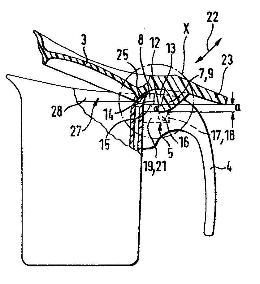
Description
Die Erfi.ndung bezieht sich sich auf ein Gefäß oder eine Kanne, insbesondere Isolierkanne, bestehend aus einem Gehäuse mit einer oberseitigen Öffnung und einem Schwenkdeckel, der in einem Schwenklager mit außerhalb der Öffnung verlaufender Schwenkachse zwischen seiner Schließstellung und seiner die Öffnung wenigstens teilweise freigebenden Offenstellung schwenkbar ist.The invention relates to a vessel or a jug, in particular an insulated jug, consisting of a housing with an opening on the top and a swivel lid which, in a swivel bearing with a swivel axis extending outside the opening, between its closed position and its open position at least partially releasing the opening is pivotable.
Bei dieser Bauart eines Schwenkdeckels ist der abnehmbare Schwenkdeckel gegen ein Herausrutschen aus dem Schwenklager in einer stark geneigten Ausgießstellung des Gefäßes durch das schwenkdeckelseitige Halteglied gesichert, daß das gehäuseseitige Halteglied auf seiner der Öffnung abgewandten Seite hintergreift. Da der Schwenkdeckel leicht abnehmbar sein soll, ist das beschriebene Hintergreifen nur geringfügig. Dies reicht als Sicherung gegen das Herausrutschen in einer stark geneigten Ausgießstellung des Gefäßes auch aus, weil das Gefäß zum Ausgießen der Restflüssigkeit nur geringfügig mehr als 90° geschwenkt wird. Um das schon erwähnte leichte Abnehmen des Schwenkdeckels zu gewährleisten, ist bei der bekannten Ausgestaltung das Schwenklager im Sinne einer Tasche ausgebildet, in die der Schwenkdeckel mit seinem deckelseitigen Halteglied eingesetzt wird. Die Einsetzbewegung ist dabei schräg zum Gefäß hin abwärts geneigt. Die Entnahmebewegung ist entgegengesetzt gerichtet.In this type of swivel cover, the removable swivel cover is secured against slipping out of the swivel bearing in a strongly inclined pouring position of the vessel by the swivel cover-side holding member, that the housing-side holding member engages behind on its side facing away from the opening. Since the swiveling lid should be easy to remove, the described reaching behind is only slight. This is also sufficient as a safeguard against slipping out in a strongly inclined pouring position of the container, because the container is only pivoted slightly more than 90 ° to pour out the residual liquid. In order to ensure that the swiveling cover can be easily removed, in the known embodiment the swiveling bearing is designed in the form of a pocket into which the swiveling cover with its cover-side holding member is inserted. The insertion movement is inclined downwards towards the vessel. The removal movement is directed in the opposite direction.
Eine solche Ausgestaltung gewährleistet zwar ein sehr einfaches und bequemes Entfernen und Wiedereinsetzen des Schwenkdeckels, jedoch hat es sich in der Praxis herausgestellt, daß es günstig ist, wenn der Schwenkdeckel in seiner Verschlußstellung verriegelt ist, so daß er in dieser seiner Stellung nicht unbeabsichtigt herausrutscht, was bei der allgemeinen Handhabung des Gefäßes z. B. durch ungeschickte Bewegungen, nicht auszuschließen ist.Such a configuration ensures a very simple and convenient removal and reinsertion of the swivel cover, but in practice it has been found that it is advantageous if the swivel cover is locked in its closed position so that it does not accidentally slip out in its position, what about the general handling of the vessel e.g. B. by clumsy movements, can not be excluded.
Der Erfindung liegt die Aufgabe zugrunde, ein Gefäß der eingangs bezeichneten Art so auszugestalten, daß der Schwenkdeckel in seiner Verschlußstellung gegen ein Abnehmen verriegelt ist.The invention has for its object to design a vessel of the type mentioned in such a way that the pivoting lid is locked in its closed position against removal.
Diese Aufgabe wird durch die im Kennzeichen des Anspruchs 1 enthaltenen Merkmale gelöst.This object is achieved by the features contained in the characterizing part of
Bei der erfindungsgemäßen Ausgestaltung sind den Haltegliedern im Schwenklager ein Arretierungsnocken und eine mit diesem zusammenwirkende Schulter zugeordnet, die eine Entfernung des Schwenkdeckels in seiner Verschlußstellung verhindern. Bei der erfindungsgemäßen Ausgestaltung springt ein Arretierungsnocken vom schwenkdeckelseitigen Halteglied nach unten vor und hintergreift in der Verschlußstellung des Schwenkdeckels eine Schulter am Schwenklager und zwar auf deren zur Öffnung hin gewandten Seite. Da der Arretierungsnocken sich nach unten erstreckt erstreckt er sich auch gleichzeitig quer zu der Bewegungsrichtung, in der der Schwenkdeckel aus dem Schwenklager entfernt werden kann. In der Verschlußstellung des Schwenkdeckels ist dieser somit nach oben durch den Hintergriff des schwenkdeckelseitigen Haltegliedes gesichert, der das schwenklagerseitige Halteglied hintergreift, und gegen eine in die Entnahmerichtung gerichtete Bewegung durch den Hintergriff gesichert, mit dem der Arretierungsnocken die Schulter hintergreift. Dieser Hintergriff wird bei der erfindungsgemäßen Ausgestaltung durch geringfügiges Öffnen, d.h. durch geringfügiges Schwenken in die Öffnungsrichtung aufgehoben, so daß der Schwenkdeckel in dieser Stellung aus dem Schwenklager entfernt oder in dieses eingesetzt werden kann. Durch das Schwenken in Schließstellung erfolgt dabei die Sicherung bzw. Verriegelung des Schwenkdeckels automatisch, weil der Arretierungsnocken vor die Schulter geschwenkt wird, wo er durch Anschlag gegen die Schulter die Entnahme des Schwenkdeckels verhindert.In the embodiment according to the invention, the holding members in the pivot bearing are assigned a locking cam and a shoulder which interacts with it and prevent the pivoting cover from being removed in its closed position. In the embodiment according to the invention, a locking cam protrudes downward from the holding member on the swiveling cover side and, in the closed position of the swiveling cover, engages behind a shoulder on the swivel bearing, namely on its side facing the opening. Since the locking cam extends downward, it also extends transversely to the direction of movement in which the swivel cover can be removed from the swivel bearing. In the closed position of the swivel cover, it is thus secured upward by the rear grip of the swivel cover-side holding member, which engages behind the swivel bearing-side holding member, and is secured against movement in the removal direction by the rear grip, with which the locking cam engages behind the shoulder. In the embodiment according to the invention, this rear grip is removed by slight opening, ie by slight pivoting in the opening direction, so that the pivoting cover can be removed from the pivot bearing in this position or inserted into it. By the pivoting in the closed position takes place the locking or locking of the swivel cover automatically because the locking cam is swiveled in front of the shoulder, where it prevents the swivel cover from being removed by a stop against the shoulder.
Dabei zeichnet sich die erfindungsgemäße Ausgestaltung durch Einfachheit aus, weil der Arretierungsnocken sich am vorhandenen schwenkdeckelseitigen Halteglied anformen läßt, und weil eine Schulter am gehäuseseitigen Halteglied sich gleichfalls in einfacher Weise herstellen läßt, z.B. durch eine taschenförmige Ausnehmung, deren dem Gehäuse entferntere Begrenzungswand die Schulter bildet, wie es im Anspruch 2 beschrieben ist.The embodiment according to the invention is characterized by simplicity because the locking cam can be molded onto the existing swiveling cover-side holding member and because a shoulder on the housing-side holding member can also be produced in a simple manner, e.g. by a pocket-shaped recess, the boundary wall of which is more distant from the housing forms the shoulder, as described in
Dabei ist es vorteilhaft, den Arretierungsnocken am das schwenkdeckelseitige Halteglied bildenden Fortsatz anzuordnen bzw. anzuformen, der annäherungsweise die gleiche Erstreckungsrichtung aufweist.It is advantageous to arrange or to form the locking cam on the extension forming the pivoting cover-side holding member, which has approximately the same direction of extension.
Bei der Ausgestaltung nach Anspruch5 sind der Arretierungsnocken und die Schulter in eine bewährte Bauart integriert, bei der zwei schwenkdeckelseitige Halteglieder vorgesehen sind, die einen Griff des Gefäßes U-förmig übergreifen, in dem die gehäuseseitigen Halteglieder eingeformt sind. Folglich sind auch bei der Ausgestaltung gemäß Anspruch 5 zu beiden Seiten des Griffs ein Arretierungsnocken und eine Schulter vorhanden.In the embodiment according to
In der Ansprüchen 6 bis 9 sind Formgebungen enthalten, die sich durch Einfachheit und Zweckmäßigkeit in funktioneller Hinsicht auszeichnen. Durch die Ausgestaltung nach Anspruch 9 werden außerdem die Arretierungsnocken zumindest teilweise abgedeckt, und diese Ausgestaltung trägt somit zur Verbesserung des angenehmen Äußeren des Gefäßes bei.In the
Nachfolgend wird ein Ausführungsbeispiel der Erfindung anhand einer vereinfachten Zeichnung beschrieben.An exemplary embodiment of the invention is described below on the basis of a simplified drawing.
Es zeigt:
- Fig. 1 ein erfindungsgemäß ausgestaltetes Gefäß in der Seitenansicht;
- Fig. 2 das Gefäß nach Fig. 1 in der Seitenansicht von rechts;
- Fig. 3 das Gefäß nach Fig. 1 mit aufgeklapptem Deckel und mit einem Teilschnitt nach Linie III-III in Fig. 2;
- Fig. 4 die in Fig. 3 mit X gekennzeichnete Einzelheit in vergrößerter Darstellung.
- 1 shows a side view of a vessel designed according to the invention;
- 2 shows the vessel according to FIG. 1 in a side view from the right;
- 3 shows the vessel according to FIG. 1 with the lid opened and with a partial section along line III-III in FIG. 2;
- Fig. 4 shows the detail marked X in Fig. 3 in an enlarged view.
Das Gefäß ist eine in Fig. 1 allgemein mit 1 bezeichnete Isolierkanne, bestehend aus einem Gehäuse 2, einem Schwenkdeckel 3 und einem Griff 4.The vessel is an insulating jug, generally designated 1 in FIG. 1, consisting of a
Das Gehäuse 2 besteht aus doppelwandigem Metallblech, wobei die Blechwände in einem Abstand voneinander angeordnet sind und sich im dazwischen gebildeten Hohlraum ein wärmedämmendes Mittel befindet. Der Schwenkdeckel 3 und der Griff 4 bestehen aus Kunststoff. Im oberen Bereich des Griffs 4 ist ein Schwenklager 5 für den Schwenkdeckel 3 angeordnet, das durch ein sogenanntes Stecklager gebildet wird. Aufgrund dieser Ausgestaltung ist es möglich, den Schwenkdeckel 3 schräg abwärts in Richtung auf die Ausgießstelle 6 der Isolierkanne 1 in das Schwenklager 5 einzustecken und in entgegengesetzter Richtung aus dem Schwenklager 5 zu entfernen. Diese Ausgestaltung ermöglicht es, den Schwenkbereich für eine teilweise Öffnung des Schwenkdeckels 3 gering zu bemessen, weil das Aufschwenken des Schwenkdeckels lediglich dem Ausgießen dient, bei dem es nur einer geringen Flüssigkeitsströmung bedarf. Zum Einfülen der Isolierkanne 1 wird der Schwenkdekcel 3 in vorbeschriebener Weise entfernt.The
Das Schwenklager 5 wird durch ein schwenkdeckelseitiges Halteglied 7 und ein gehäuseseitiges Halteglied 8 gebildet, die formschlüssig ineinandergreifen. Das deckelseitige Halteglied 7 ist durch einen hakenförmigen Fortsatz 9 gebildet, der zunächst radial auswärts verläuft und nach unten hakenförmig zurückspringt. Durch eine radial verlaufende Ausnehmung 11 im Fortsatz 9 sind voneinander beabstandete Hakenspitzen 12 gebildet, die in auf beiden Seiten im Griff 4 angeordneten, aufwärts geöffneten Aussparungen 13 eintauchen. Die Hakenspitzen 12 übergreifen und hintergreifen die beiderseits vorhandenen Halteglieder 8 bzw. deren gehäuseferne Wände 14 und Unterseiten 15, die zugleich gehäusenahe Wände der Aussparung 13 bilden. Die Fortsätze 9 bzw. die Hakenspitzen 12 haben in den Aussparungen 13 ein Schwenkspiel, das die teilweise Öffnung des Gehäuses 2 ermöglicht.The pivot bearing 5 is formed by a holding member 7 on the swiveling cover side and a
Vom unteren Ende jedes Fortsatzes 9 erstreckt sich ein Arretierungsnocken 16 nach unten, der in der Schließstellung des Schwenkdeckels 3 nahe einer Schulter 17 liegt, die durch die gehäuseferne Wand 18 der Aussparung 13 gebildet wird. Dabei fassen die Arretierungsnocken 16 in taschenförmige Ausnehmungen 19 ein, die seitlich durch Seitenwände 21 des Griffs 4 abgedeckt sind. Die taschenförmigen Ausnehmungen 19 sind Verlängerungen der Aussparung 13 und laufen auf der dem Gehäuse 2 zugewandten Seite des durch eine nicht dargestellte Schraube lösbar befestigten Griffs 4 aus.From the lower end of each extension 9, a
In der Verschlußstellung (Fig. 1) befinden sich der Arretierungsnocken 16 direkt vor der Schulter 17, und die Hakenspitzen 12 hinter- und untergreifen das gehäuseseitige Halteglied 8. Da die Länge 1 der Arretierungsnocken größer bemessen ist als das Spiel s zwischen den Haltegliedern 8 und den Hakenspitzen 12, ist die Entnahme des Schwenkdeckels 3 verhindert.In the closed position (FIG. 1), the
In der in Fig. 3 und 4 dargestellten Offenstellung des Schwenkdeckels 3 sind die Arretierungsnocken 16 von der Schulter 17 weggeschwenkt. Hierdurch wird die Wirksamkeit der Verriegelung aufgehoben, wenn die Hakenspitzen 12 in Richtung des Doppelpfeils 22 entnommen werden. Dabei erweist sich ein Abstand a zwischen der Unterseite 15 des gehäuseseitigen Haltegliedes 8 und dem oberen Ende der Schulter 17 als günstig. Der Schwenkdeckel kann entlang des Doppelpfeils 22 aus dem Schwenklager 5 entnommen und wieder eingesetzt werden. Das Aufschwenken des Schwenkdeckels 3 erfolgt durch Druck auf einen Drücker 23, der sich oberhalb des Griffs 4 radial auswärts erstreckt und beispielsweise mit dem Daumen der die Isolierkanne 1 am Griff erfassenden Bedienungshand heruntergedrückt werden kann. Das Schließen des Schwenkdeckels 3 erfolgt automatisch durch die Schwerkraft des Schwenkdeckels 3.In the open position of the
Die über die Hakenspitzen 12 gemessene Breite B entspricht der Breite des Griffs 4. Die äußere Begrenzung der Hakenspitze 12 gleicht deshalb mit den Seiten des Griffs 4 ab. Um den Hakenspitzen 12 eine größere Festigkeit zu verleihen, sind an beiden Außenseiten der Hakenspitze 12 Wände 24 als Versteifungsrippen vorgesehen, die vom Rand 25 des Schwenkdeckels 3 ausgehen und mit den Außenseiten der Hakenspitze 12 verbunden sind. Im Rahmen der Erfindung gibt es viele Möglichkeiten, die Wände 24 sowohl mit dem Rand 25 des Schwenkdeckels 3 als auch mit den Hakenspitzen 12 zu verbinden, beispielsweise durch Kleben. In bevorzugter Ausgestaltung sind die Wände 24 einstückig an den Schwenkdeckel 3 und jeweils eine Hakenspitze 12 bzw. das schwenkdeckelseitige Halteglied 7 angeformt.The width B measured via the
Die Wände 24 verleihen den Hakenspitzen 12 bzw. dem schwenkdeckelseitigen Halteglied 7 nicht nur eine hohe Stabilität, sondern sie erweisen sich auch als Führungsflächen, indem sie mit ihren Innenseiten den Griff 4 mit Bewegungsspiel zwischen sich einschließen. Außerdem stellen die Wände 24 einen Sichtschutz dar, der die Halteglieder 7, 8 sowie die Aussparung 13 im Griff 4 verdeckt. Da die Wände 24 an der Schwenkbewegung des Schwenkdeckels 3 teilnehmen, empfiehlt es sich ihre Ränder 26 zu runden. Es ist auch möglich, den Abstand B zwischen den Haltegliedern 7 mit den Tiefen t der Aussparungen 13 so abzustimmen, daß hierdurch die seitliche Führung gebildet ist.The
Nicht nur die Wände 24 und die Hakenspitzen 12 bilden ein einstückiges Bauteil, sondern auch der Drücker 23 geht aus diesem Bauteil einstückig hervor. Das schwenkdeckelseitige Halteglied 7, die Wände 24 und der Drücker 23 bilden somit eine stabile Anformung am Schwenkdeckel 3, die sich aufgrund der besonderen Ausgestaltung einfach insbesondere durch Spritzgießen von Kunststoff herstellen läßt.Not only the
Es ist möglich, den Drücker 23 so anzuordnen, daß er in der gewünschten (teilweisen) Öffnung des Gehäuses 2 auf dem Griff 4 aufliegt.It is possible to arrange the
Der die Öffnung 27 des Gehäuses 2 begrenzende obere Rand 28 ist nach außen schräg aufwärts verlaufend ausgebogen.The
Der Rand 25 des Schwenkdeckels 3 ist an den Rand 28 des Gehäuses 2 angepaßt und verläuft schräg aufwärts. In der Schließstellung liegen die Ränder 25, 28 aneinander an. Hierdurch wird auf der dem Griff 4 zugewandten Seite der Öffnung 27 eine schiefe Ebene geschaffen, die in Richtung der Entnahme- bzw. Einsetzrichtung (Doppelpfeil 22) wirksam ist und in die Verriegelung bzw. Arretierung des Schwenkdeckels 3 einbezogen sein kann.The
Im Rahmen der Erfindung ist es möglich, anders geformte schwenkdeckelseitige und gehäuseseitige Halteglieder 7, 8 einzusetzen, obwohl die vorbeschriebenen Halteglieder 7, 8 eine bevorzugte Ausgestaltungsform darstellen.In the context of the invention it is possible to use differently shaped pivoting cover-side and housing-
Es sind auch andere Grifformen und -befestigungen möglich als die dargestellte Grifform, bei der der Griff sich zunächst radial auswärts erstreckt und dann nach unten abgebogen ist. Der dargestellte Griff 4 weist eine bevorzugte Form auf, wobei seine einseitige Befestigung nicht näher dargestellt ist und beispielsweise durch Kleben oder Schrauben erfolgen kann.Handle shapes and attachments other than the handle shape shown are also possible, in which the handle initially extends radially outward and is then bent downward. The
Claims (9)
Applications Claiming Priority (2)
| Application Number | Priority Date | Filing Date | Title |
|---|---|---|---|
| DE3525378 | 1985-07-16 | ||
| DE19853525378 DE3525378A1 (en) | 1985-07-16 | 1985-07-16 | VESSEL OR JUG WITH A REMOVABLE PIVOTING LID |
Publications (2)
| Publication Number | Publication Date |
|---|---|
| EP0209042A2 true EP0209042A2 (en) | 1987-01-21 |
| EP0209042A3 EP0209042A3 (en) | 1987-07-15 |
Family
ID=6275908
Family Applications (1)
| Application Number | Title | Priority Date | Filing Date |
|---|---|---|---|
| EP86109273A Withdrawn EP0209042A3 (en) | 1985-07-16 | 1986-07-07 | Vessel or jug with a removable hinged lid |
Country Status (13)
| Country | Link |
|---|---|
| US (1) | US4669631A (en) |
| EP (1) | EP0209042A3 (en) |
| AU (1) | AU5893086A (en) |
| DE (1) | DE3525378A1 (en) |
| DK (1) | DK263086A (en) |
| ES (1) | ES294740Y (en) |
| FI (1) | FI862357A7 (en) |
| GR (1) | GR861465B (en) |
| IL (1) | IL79067A0 (en) |
| IS (1) | IS3108A7 (en) |
| NO (1) | NO862355L (en) |
| PT (1) | PT82956A (en) |
| ZA (1) | ZA864439B (en) |
Cited By (4)
| Publication number | Priority date | Publication date | Assignee | Title |
|---|---|---|---|---|
| WO1990007895A1 (en) * | 1989-01-18 | 1990-07-26 | Hp Haushaltprodukte Vertriebs Gmbh | Container for liquids, in particular microwave pot |
| EP0354942B1 (en) * | 1988-01-21 | 1992-04-15 | Hölter, Heinz, Dipl.-Ing. | Process for preventing exposure to chemically and/or biologically harmful substances given off by building surfaces |
| US5137168A (en) * | 1990-02-13 | 1992-08-11 | Braun Aktiengesellschaft | Jug for storing hot beverages, in particular coffee or tea |
| EP0894463A1 (en) * | 1997-07-30 | 1999-02-03 | MILKE, Siegfried | Insulated jug and lid therefor |
Families Citing this family (5)
| Publication number | Priority date | Publication date | Assignee | Title |
|---|---|---|---|---|
| GB2257349B (en) * | 1992-02-06 | 1995-09-27 | Brandon Brandon | Pouring device |
| US20120145705A1 (en) * | 2010-12-10 | 2012-06-14 | Tiffany Wilt | Separable Beverage Containers |
| USD755046S1 (en) * | 2014-06-27 | 2016-05-03 | Johnson & Johnson Consumer Inc. | Package actuator |
| USD816497S1 (en) * | 2014-06-27 | 2018-05-01 | Johnson & Johnson Consumer Inc. | Package actuator |
| USD816496S1 (en) * | 2014-06-27 | 2018-05-01 | Johnson & Johnson Consumer Inc. | Package actuator |
Family Cites Families (7)
| Publication number | Priority date | Publication date | Assignee | Title |
|---|---|---|---|---|
| DE46614C (en) * | F. HERBST in Halle a. S | Removable vessel lid | ||
| GB140213A (en) * | 1919-03-28 | 1920-03-25 | Taylor Marsden | Improvements in and relating to the fitting and securing of lids to cans, bottles and other receptacles |
| US2342477A (en) * | 1941-08-08 | 1944-02-22 | Waterbury Button Company | Plastic hinge cap |
| DE816300C (en) * | 1950-06-20 | 1951-10-08 | Ph Leman A G | Hinged lid lock, especially for mustard containers |
| US2944691A (en) * | 1957-05-15 | 1960-07-12 | Anthony W Serio | Receptacle and cover therefor |
| US4301942A (en) * | 1978-05-15 | 1981-11-24 | Rb Products Corporation | Insulated container |
| US4519520A (en) * | 1984-08-20 | 1985-05-28 | Hill Charles A | Vessel lid attachment |
-
1985
- 1985-07-16 DE DE19853525378 patent/DE3525378A1/en not_active Withdrawn
-
1986
- 1986-06-03 FI FI862357A patent/FI862357A7/en not_active Application Discontinuation
- 1986-06-04 DK DK263086A patent/DK263086A/en not_active Application Discontinuation
- 1986-06-05 GR GR861465A patent/GR861465B/en unknown
- 1986-06-09 IL IL79067A patent/IL79067A0/en unknown
- 1986-06-11 IS IS3108A patent/IS3108A7/en unknown
- 1986-06-12 NO NO862355A patent/NO862355L/en unknown
- 1986-06-13 US US06/873,960 patent/US4669631A/en not_active Expired - Fee Related
- 1986-06-13 ZA ZA864439A patent/ZA864439B/en unknown
- 1986-06-13 ES ES1986294740U patent/ES294740Y/en not_active Expired
- 1986-06-20 AU AU58930/86A patent/AU5893086A/en not_active Abandoned
- 1986-07-07 EP EP86109273A patent/EP0209042A3/en not_active Withdrawn
- 1986-07-10 PT PT82956A patent/PT82956A/en not_active Application Discontinuation
Cited By (4)
| Publication number | Priority date | Publication date | Assignee | Title |
|---|---|---|---|---|
| EP0354942B1 (en) * | 1988-01-21 | 1992-04-15 | Hölter, Heinz, Dipl.-Ing. | Process for preventing exposure to chemically and/or biologically harmful substances given off by building surfaces |
| WO1990007895A1 (en) * | 1989-01-18 | 1990-07-26 | Hp Haushaltprodukte Vertriebs Gmbh | Container for liquids, in particular microwave pot |
| US5137168A (en) * | 1990-02-13 | 1992-08-11 | Braun Aktiengesellschaft | Jug for storing hot beverages, in particular coffee or tea |
| EP0894463A1 (en) * | 1997-07-30 | 1999-02-03 | MILKE, Siegfried | Insulated jug and lid therefor |
Also Published As
| Publication number | Publication date |
|---|---|
| ZA864439B (en) | 1987-02-25 |
| IS3108A7 (en) | 1987-01-17 |
| GR861465B (en) | 1986-09-01 |
| AU5893086A (en) | 1987-01-22 |
| FI862357A0 (en) | 1986-06-03 |
| DE3525378A1 (en) | 1987-01-22 |
| ES294740U (en) | 1986-11-16 |
| DK263086A (en) | 1987-01-17 |
| US4669631A (en) | 1987-06-02 |
| NO862355D0 (en) | 1986-06-12 |
| FI862357A7 (en) | 1987-01-17 |
| EP0209042A3 (en) | 1987-07-15 |
| DK263086D0 (en) | 1986-06-04 |
| PT82956A (en) | 1986-08-01 |
| ES294740Y (en) | 1987-08-01 |
| NO862355L (en) | 1987-01-19 |
| IL79067A0 (en) | 1986-09-30 |
Similar Documents
| Publication | Publication Date | Title |
|---|---|---|
| DE60111832T2 (en) | REMOVABLE AUXILIARY EQUIPMENT FOR MEALS | |
| DE69326959T2 (en) | STACKABLE MUG | |
| DE8614126U1 (en) | Containers, especially paint boxes | |
| DE2133296A1 (en) | SLIDING BOX | |
| DE202015106824U1 (en) | Pet crate | |
| DE3525378A1 (en) | VESSEL OR JUG WITH A REMOVABLE PIVOTING LID | |
| DE4304484A1 (en) | Containers, in particular drawer-like containers | |
| DE102007035475A1 (en) | Compact cosmetics box | |
| DE102015121865A1 (en) | Pet crate | |
| DE8520526U1 (en) | Vessel or jug with a removable swivel lid | |
| DE29922447U1 (en) | Sealable container | |
| EP0212346B1 (en) | Container for documents | |
| DE3139112C2 (en) | Swivel lid closure of containers | |
| DE3218853A1 (en) | Container, such as a frying pan and the like, provided with a handle | |
| CH629271A5 (en) | Securing means for WC deodorisers | |
| DE3418228A1 (en) | Vessel or jug, in particular insulating jug having a hinged lid | |
| DE2809705C2 (en) | Container for hanging files and the like. | |
| DE20008365U1 (en) | Swing lid container | |
| EP1345814A1 (en) | Reservoir | |
| DE7010482U (en) | TWO-PIECE PLASTIC CONNECTOR, SO-CALLED CONNECTOR. | |
| DE29922432U1 (en) | Folding box | |
| DE8402971U1 (en) | ROAST OR COOKING VESSEL | |
| DE8900513U1 (en) | Liquid container | |
| DE29504866U1 (en) | Collapsible wire basket | |
| DE2006676C3 (en) | Hang-on lock for suitcases, bags and similar containers |
Legal Events
| Date | Code | Title | Description |
|---|---|---|---|
| PUAI | Public reference made under article 153(3) epc to a published international application that has entered the european phase |
Free format text: ORIGINAL CODE: 0009012 |
|
| AK | Designated contracting states |
Kind code of ref document: A2 Designated state(s): AT BE CH DE FR GB IT LI LU NL SE |
|
| PUAL | Search report despatched |
Free format text: ORIGINAL CODE: 0009013 |
|
| AK | Designated contracting states |
Kind code of ref document: A3 Designated state(s): AT BE CH DE FR GB IT LI LU NL SE |
|
| 17P | Request for examination filed |
Effective date: 19870710 |
|
| 17Q | First examination report despatched |
Effective date: 19880726 |
|
| STAA | Information on the status of an ep patent application or granted ep patent |
Free format text: STATUS: THE APPLICATION HAS BEEN WITHDRAWN |
|
| 18W | Application withdrawn |
Withdrawal date: 19880921 |
|
| RIN1 | Information on inventor provided before grant (corrected) |
Inventor name: ZIMMERMANN, ANSO, DR. |