EP0209042A2 - Récipient ou pot avec un couvercle amovible et articulé - Google Patents
Récipient ou pot avec un couvercle amovible et articulé Download PDFInfo
- Publication number
- EP0209042A2 EP0209042A2 EP86109273A EP86109273A EP0209042A2 EP 0209042 A2 EP0209042 A2 EP 0209042A2 EP 86109273 A EP86109273 A EP 86109273A EP 86109273 A EP86109273 A EP 86109273A EP 0209042 A2 EP0209042 A2 EP 0209042A2
- Authority
- EP
- European Patent Office
- Prior art keywords
- housing
- holding member
- vessel
- opening
- cover
- Prior art date
- Legal status (The legal status is an assumption and is not a legal conclusion. Google has not performed a legal analysis and makes no representation as to the accuracy of the status listed.)
- Withdrawn
Links
Images

Classifications
-
- B—PERFORMING OPERATIONS; TRANSPORTING
- B65—CONVEYING; PACKING; STORING; HANDLING THIN OR FILAMENTARY MATERIAL
- B65D—CONTAINERS FOR STORAGE OR TRANSPORT OF ARTICLES OR MATERIALS, e.g. BAGS, BARRELS, BOTTLES, BOXES, CANS, CARTONS, CRATES, DRUMS, JARS, TANKS, HOPPERS, FORWARDING CONTAINERS; ACCESSORIES, CLOSURES, OR FITTINGS THEREFOR; PACKAGING ELEMENTS; PACKAGES
- B65D51/00—Closures not otherwise provided for
- B65D51/02—Loosely-engaging lids or covers for jars, cans or like containers for liquids without means for effecting sealing of container
- B65D51/04—Loosely-engaging lids or covers for jars, cans or like containers for liquids without means for effecting sealing of container hinged
-
- A—HUMAN NECESSITIES
- A47—FURNITURE; DOMESTIC ARTICLES OR APPLIANCES; COFFEE MILLS; SPICE MILLS; SUCTION CLEANERS IN GENERAL
- A47G—HOUSEHOLD OR TABLE EQUIPMENT
- A47G19/00—Table service
- A47G19/12—Vessels or pots for table use
-
- A—HUMAN NECESSITIES
- A47—FURNITURE; DOMESTIC ARTICLES OR APPLIANCES; COFFEE MILLS; SPICE MILLS; SUCTION CLEANERS IN GENERAL
- A47G—HOUSEHOLD OR TABLE EQUIPMENT
- A47G19/00—Table service
- A47G19/12—Vessels or pots for table use
- A47G19/127—Vessels or pots for table use with means for keeping liquid cool or hot
Definitions
- the invention relates to a vessel or a jug, in particular an insulated jug, consisting of a housing with an opening on the top and a swivel lid which, in a swivel bearing with a swivel axis extending outside the opening, between its closed position and its open position at least partially releasing the opening is pivotable.
- the removable swivel cover is secured against slipping out of the swivel bearing in a strongly inclined pouring position of the vessel by the swivel cover-side holding member, that the housing-side holding member engages behind on its side facing away from the opening. Since the swiveling lid should be easy to remove, the described reaching behind is only slight. This is also sufficient as a safeguard against slipping out in a strongly inclined pouring position of the container, because the container is only pivoted slightly more than 90 ° to pour out the residual liquid.
- the swiveling bearing is designed in the form of a pocket into which the swiveling cover with its cover-side holding member is inserted.
- the insertion movement is inclined downwards towards the vessel.
- the removal movement is directed in the opposite direction.
- the invention has for its object to design a vessel of the type mentioned in such a way that the pivoting lid is locked in its closed position against removal.
- the holding members in the pivot bearing are assigned a locking cam and a shoulder which interacts with it and prevent the pivoting cover from being removed in its closed position.
- a locking cam protrudes downward from the holding member on the swiveling cover side and, in the closed position of the swiveling cover, engages behind a shoulder on the swivel bearing, namely on its side facing the opening. Since the locking cam extends downward, it also extends transversely to the direction of movement in which the swivel cover can be removed from the swivel bearing.
- the embodiment according to the invention is characterized by simplicity because the locking cam can be molded onto the existing swiveling cover-side holding member and because a shoulder on the housing-side holding member can also be produced in a simple manner, e.g. by a pocket-shaped recess, the boundary wall of which is more distant from the housing forms the shoulder, as described in claim 2.
- the locking cam and the shoulder are integrated into a proven design, in which two pivoting cover-side holding members are provided which overlap a handle of the vessel in a U-shape, in which the housing-side holding members are molded. Consequently, a locking cam and a shoulder are also present in the embodiment according to claim 5 on both sides of the handle.
- the vessel is an insulating jug, generally designated 1 in FIG. 1, consisting of a housing 2, a pivoting lid 3 and a handle 4.
- the housing 2 consists of double-walled metal sheet, the sheet metal walls being arranged at a distance from one another and a heat-insulating agent being located in the cavity formed between them.
- the swivel cover 3 and the handle 4 are made of plastic.
- a pivot bearing 5 for the pivot cover 3 is arranged, which is formed by a so-called plug-in bearing. Because of this configuration, it is possible to insert the swivel cover 3 obliquely downwards in the direction of the pouring point 6 of the vacuum jug 1 into the swivel bearing 5 and in the opposite direction ter direction to remove from the pivot bearing 5.
- This configuration makes it possible to dimension the swivel area small for a partial opening of the swivel cover 3, because the swiveling open of the swivel cover only serves for pouring out, in which only a small liquid flow is required.
- the swivel decoration 3 is removed in the manner described above.
- the pivot bearing 5 is formed by a holding member 7 on the swiveling cover side and a holding member 8 on the housing side, which engage in a form-fitting manner.
- the cover-side holding member 7 is formed by a hook-shaped extension 9, which initially extends radially outwards and springs back in a hook-shaped manner.
- a radially extending recess 11 in the extension 9 forms hook tips 12 which are spaced apart from one another and which dip into recesses 13 which are arranged on both sides in the handle 4 and open upwards.
- the hook tips 12 overlap and engage behind the holding members 8 which are present on both sides or their walls 14 and undersides 15 remote from the housing, which at the same time form the walls of the recess 13 near the housing.
- the extensions 9 and the hook tips 12 have a swivel play in the recesses 13, which enables the partial opening of the housing 2.
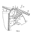
- a locking cam 16 extends downward, which in the closed position of the swivel cover 3 is close to a shoulder 17 which is formed by the wall 18 of the recess 13 remote from the housing.
- the locking cams 16 enclose in pocket-shaped recesses 19 which are laterally covered by side walls 21 of the handle 4.
- the pocket-shaped recesses 19 are extensions of the recess 13 and run on the housing 2 facing side of the handle 4 releasably attached by a screw, not shown.
- the locking cams 16 are located directly in front of the shoulder 17, and the hook tips 12 reach behind and under the housing-side holding member 8. Since the length 1 of the locking cams is larger than the play s between the holding members 8 and the hook tips 12, the removal of the swivel cover 3 is prevented.
- the locking cams 16 are swiveled away from the shoulder 17.
- a distance a between the underside 15 of the housing-side holding member 8 and the upper end of the shoulder 17 proves to be favorable.
- the swivel cover can be removed from the swivel bearing 5 and reinserted along the double arrow 22.
- the pivoting lid 3 is swung open by pressing a push button 23 which extends radially outward above the handle 4 and can be pressed down, for example, with the thumb of the operating hand grasping the vacuum jug 1 on the handle.
- the swivel cover 3 is closed automatically by the force of gravity of the swivel cover 3.
- the width B measured via the hook tips 12 corresponds to the width of the handle 4.
- the outer boundary of the hook tip 12 therefore matches the sides of the handle 4.
- 12 walls 24 are provided as stiffening ribs on both outer sides of the hook tip, which extend from the edge 25 of the swivel cover 3 and with the Outside of the hook tip 12 are connected.
- the walls 24 are integrally formed on the swivel cover 3 and in each case a hook tip 12 or the swivel cover-side holding member 7.
- the walls 24 not only give the hook tips 12 or the swiveling cover-side holding member 7 a high degree of stability, but they also prove to be guide surfaces in that the inside of them enclose the handle 4 with play between them.
- the walls 24 represent a privacy screen that covers the holding members 7, 8 and the recess 13 in the handle 4. Since the walls 24 participate in the swiveling movement of the swiveling cover 3, it is advisable to round their edges 26. It is also possible to coordinate the distance B between the holding members 7 with the depths t of the recesses 13 so that the lateral guide is formed as a result.
- the walls 24 and the hook tips 12 form a one-piece component, but also the pusher 23 emerges in one piece from this component.
- the swiveling cover-side holding member 7, the walls 24 and the pusher 23 thus form a stable molding on the swiveling cover 3 which, owing to the special configuration, can be easily produced, in particular by injection molding of plastic.
- the upper edge 28, which delimits the opening 27 of the housing 2, is bent outwards and runs obliquely upwards.
- the edge 25 of the swivel cover 3 is adapted to the edge 28 of the housing 2 and extends obliquely upwards. In the closed position, the edges 25, 28 abut one another. This creates an inclined plane on the side of the opening 27 facing the handle 4, which is effective in the direction of the removal or insertion direction (double arrow 22) and can be included in the locking or locking of the swivel cover 3.
- pivoting cover-side and housing-side holding members 7, 8 Although the above-described holding members 7, 8 represent a preferred embodiment.
- Handle shapes and attachments other than the handle shape shown are also possible, in which the handle initially extends radially outward and is then bent downward.
- the handle 4 shown has a preferred shape, its one-sided attachment is not shown in detail and can be done for example by gluing or screwing.
Landscapes
- Engineering & Computer Science (AREA)
- Mechanical Engineering (AREA)
- Closures For Containers (AREA)
- Table Devices Or Equipment (AREA)
- Centrifugal Separators (AREA)
- Details Of Rigid Or Semi-Rigid Containers (AREA)
Applications Claiming Priority (2)
| Application Number | Priority Date | Filing Date | Title |
|---|---|---|---|
| DE3525378 | 1985-07-16 | ||
| DE19853525378 DE3525378A1 (de) | 1985-07-16 | 1985-07-16 | Gefaess oder kanne mit einem abnehmbaren schwenkdeckel |
Publications (2)
| Publication Number | Publication Date |
|---|---|
| EP0209042A2 true EP0209042A2 (fr) | 1987-01-21 |
| EP0209042A3 EP0209042A3 (fr) | 1987-07-15 |
Family
ID=6275908
Family Applications (1)
| Application Number | Title | Priority Date | Filing Date |
|---|---|---|---|
| EP86109273A Withdrawn EP0209042A3 (fr) | 1985-07-16 | 1986-07-07 | Récipient ou pot avec un couvercle amovible et articulé |
Country Status (13)
| Country | Link |
|---|---|
| US (1) | US4669631A (fr) |
| EP (1) | EP0209042A3 (fr) |
| AU (1) | AU5893086A (fr) |
| DE (1) | DE3525378A1 (fr) |
| DK (1) | DK263086A (fr) |
| ES (1) | ES294740Y (fr) |
| FI (1) | FI862357A7 (fr) |
| GR (1) | GR861465B (fr) |
| IL (1) | IL79067A0 (fr) |
| IS (1) | IS3108A7 (fr) |
| NO (1) | NO862355L (fr) |
| PT (1) | PT82956A (fr) |
| ZA (1) | ZA864439B (fr) |
Cited By (4)
| Publication number | Priority date | Publication date | Assignee | Title |
|---|---|---|---|---|
| WO1990007895A1 (fr) * | 1989-01-18 | 1990-07-26 | Hp Haushaltprodukte Vertriebs Gmbh | Recipient pour liquides, notamment pot pour four a micro-ondes |
| EP0354942B1 (fr) * | 1988-01-21 | 1992-04-15 | Hölter, Heinz, Dipl.-Ing. | Procede pour eviter les nuisances produites par les polluants chimiques et/ou biologiques, emises par les surfaces des batiments |
| US5137168A (en) * | 1990-02-13 | 1992-08-11 | Braun Aktiengesellschaft | Jug for storing hot beverages, in particular coffee or tea |
| EP0894463A1 (fr) * | 1997-07-30 | 1999-02-03 | MILKE, Siegfried | Pot à isolation thermique et couvercle |
Families Citing this family (5)
| Publication number | Priority date | Publication date | Assignee | Title |
|---|---|---|---|---|
| GB2257349B (en) * | 1992-02-06 | 1995-09-27 | Brandon Brandon | Pouring device |
| US20120145705A1 (en) * | 2010-12-10 | 2012-06-14 | Tiffany Wilt | Separable Beverage Containers |
| USD816497S1 (en) * | 2014-06-27 | 2018-05-01 | Johnson & Johnson Consumer Inc. | Package actuator |
| USD755046S1 (en) * | 2014-06-27 | 2016-05-03 | Johnson & Johnson Consumer Inc. | Package actuator |
| USD816496S1 (en) * | 2014-06-27 | 2018-05-01 | Johnson & Johnson Consumer Inc. | Package actuator |
Family Cites Families (7)
| Publication number | Priority date | Publication date | Assignee | Title |
|---|---|---|---|---|
| DE46614C (de) * | F. HERBST in Halle a. S | Abnehmbarer Gefäfsdeckel | ||
| GB140213A (en) * | 1919-03-28 | 1920-03-25 | Taylor Marsden | Improvements in and relating to the fitting and securing of lids to cans, bottles and other receptacles |
| US2342477A (en) * | 1941-08-08 | 1944-02-22 | Waterbury Button Company | Plastic hinge cap |
| DE816300C (de) * | 1950-06-20 | 1951-10-08 | Ph Leman A G | Klappdeckelverschluss, insbesondere fuer Senfbehaelter |
| US2944691A (en) * | 1957-05-15 | 1960-07-12 | Anthony W Serio | Receptacle and cover therefor |
| US4301942A (en) * | 1978-05-15 | 1981-11-24 | Rb Products Corporation | Insulated container |
| US4519520A (en) * | 1984-08-20 | 1985-05-28 | Hill Charles A | Vessel lid attachment |
-
1985
- 1985-07-16 DE DE19853525378 patent/DE3525378A1/de not_active Withdrawn
-
1986
- 1986-06-03 FI FI862357A patent/FI862357A7/fi not_active Application Discontinuation
- 1986-06-04 DK DK263086A patent/DK263086A/da not_active Application Discontinuation
- 1986-06-05 GR GR861465A patent/GR861465B/el unknown
- 1986-06-09 IL IL79067A patent/IL79067A0/xx unknown
- 1986-06-11 IS IS3108A patent/IS3108A7/is unknown
- 1986-06-12 NO NO862355A patent/NO862355L/no unknown
- 1986-06-13 ES ES1986294740U patent/ES294740Y/es not_active Expired
- 1986-06-13 ZA ZA864439A patent/ZA864439B/xx unknown
- 1986-06-13 US US06/873,960 patent/US4669631A/en not_active Expired - Fee Related
- 1986-06-20 AU AU58930/86A patent/AU5893086A/en not_active Abandoned
- 1986-07-07 EP EP86109273A patent/EP0209042A3/fr not_active Withdrawn
- 1986-07-10 PT PT82956A patent/PT82956A/pt not_active Application Discontinuation
Cited By (4)
| Publication number | Priority date | Publication date | Assignee | Title |
|---|---|---|---|---|
| EP0354942B1 (fr) * | 1988-01-21 | 1992-04-15 | Hölter, Heinz, Dipl.-Ing. | Procede pour eviter les nuisances produites par les polluants chimiques et/ou biologiques, emises par les surfaces des batiments |
| WO1990007895A1 (fr) * | 1989-01-18 | 1990-07-26 | Hp Haushaltprodukte Vertriebs Gmbh | Recipient pour liquides, notamment pot pour four a micro-ondes |
| US5137168A (en) * | 1990-02-13 | 1992-08-11 | Braun Aktiengesellschaft | Jug for storing hot beverages, in particular coffee or tea |
| EP0894463A1 (fr) * | 1997-07-30 | 1999-02-03 | MILKE, Siegfried | Pot à isolation thermique et couvercle |
Also Published As
| Publication number | Publication date |
|---|---|
| DK263086D0 (da) | 1986-06-04 |
| US4669631A (en) | 1987-06-02 |
| IL79067A0 (en) | 1986-09-30 |
| NO862355L (no) | 1987-01-19 |
| ES294740U (es) | 1986-11-16 |
| EP0209042A3 (fr) | 1987-07-15 |
| PT82956A (en) | 1986-08-01 |
| NO862355D0 (no) | 1986-06-12 |
| ES294740Y (es) | 1987-08-01 |
| IS3108A7 (is) | 1987-01-17 |
| FI862357A0 (fi) | 1986-06-03 |
| DK263086A (da) | 1987-01-17 |
| AU5893086A (en) | 1987-01-22 |
| DE3525378A1 (de) | 1987-01-22 |
| GR861465B (en) | 1986-09-01 |
| ZA864439B (en) | 1987-02-25 |
| FI862357A7 (fi) | 1987-01-17 |
Similar Documents
| Publication | Publication Date | Title |
|---|---|---|
| DE60111832T2 (de) | Aufsteckbare hilfseinrichtung für mahlzeiten | |
| DE69326959T2 (de) | Stapelbarer becher | |
| DE8614126U1 (de) | Behälter, insbesondere Farbkasten | |
| DE2133296A1 (de) | Schiebe-schachtel | |
| DE202015106824U1 (de) | Transportbox | |
| EP0209042A2 (fr) | Récipient ou pot avec un couvercle amovible et articulé | |
| DE4304484A1 (de) | Behälter, insbesondere schubladenartiger Behälter | |
| DE102007035475A1 (de) | Kompakte Kosmetikbox | |
| DE102015121865A1 (de) | Transportbox | |
| DE8520526U1 (de) | Gefäß oder Kanne mit einem abnehmbaren Schwenkdeckel | |
| DE29922447U1 (de) | Abdichtbarer Behälter | |
| EP0212346B1 (fr) | Récipient pour documents | |
| DE3139112C2 (de) | Schwenkdeckelverschluß von Behältern | |
| DE3218853A1 (de) | Mit einem griff versehener behaelter, wie bratpfanne u. dergl. | |
| CH629271A5 (en) | Securing means for WC deodorisers | |
| DE3418228A1 (de) | Gefaess oder kanne, insbesondere isolierkanne mit einem schwenkdeckel | |
| DE20008365U1 (de) | Schwenkdeckelbehälter | |
| EP1345814A1 (fr) | Recipient de stockage | |
| DE7010482U (de) | Zweiteiliger kunststoff-steckverschluss, sogenanntes steckschloss. | |
| DE29922432U1 (de) | Faltschachtel | |
| DE8402971U1 (de) | Brat- oder kochgefaess | |
| DE8900513U1 (de) | Flüssigkeitsbehälter | |
| DE29504866U1 (de) | Zusammenklappbarer Drahtkorb | |
| DE2006676C3 (de) | EinhängeverschluB für Koffer, Taschen und dergleichen Behälter | |
| DE365826C (de) | Zahnstocherbehaelter mit im Entnahmeschlitz angebrachter Sperrvorrichtung zur Verhuetung des Zuruecklegens gebrauchter Zahnstocher |
Legal Events
| Date | Code | Title | Description |
|---|---|---|---|
| PUAI | Public reference made under article 153(3) epc to a published international application that has entered the european phase |
Free format text: ORIGINAL CODE: 0009012 |
|
| AK | Designated contracting states |
Kind code of ref document: A2 Designated state(s): AT BE CH DE FR GB IT LI LU NL SE |
|
| PUAL | Search report despatched |
Free format text: ORIGINAL CODE: 0009013 |
|
| AK | Designated contracting states |
Kind code of ref document: A3 Designated state(s): AT BE CH DE FR GB IT LI LU NL SE |
|
| 17P | Request for examination filed |
Effective date: 19870710 |
|
| 17Q | First examination report despatched |
Effective date: 19880726 |
|
| STAA | Information on the status of an ep patent application or granted ep patent |
Free format text: STATUS: THE APPLICATION HAS BEEN WITHDRAWN |
|
| 18W | Application withdrawn |
Withdrawal date: 19880921 |
|
| RIN1 | Information on inventor provided before grant (corrected) |
Inventor name: ZIMMERMANN, ANSO, DR. |