EP0209091A2 - Procédé de fabrication d'une armature d'un générateur à courant alternatif pour véhicule - Google Patents
Procédé de fabrication d'une armature d'un générateur à courant alternatif pour véhicule Download PDFInfo
- Publication number
- EP0209091A2 EP0209091A2 EP86109513A EP86109513A EP0209091A2 EP 0209091 A2 EP0209091 A2 EP 0209091A2 EP 86109513 A EP86109513 A EP 86109513A EP 86109513 A EP86109513 A EP 86109513A EP 0209091 A2 EP0209091 A2 EP 0209091A2
- Authority
- EP
- European Patent Office
- Prior art keywords
- coil
- stator
- slots
- splitted
- armature
- Prior art date
- Legal status (The legal status is an assumption and is not a legal conclusion. Google has not performed a legal analysis and makes no representation as to the accuracy of the status listed.)
- Granted
Links
Images


Classifications
-
- H—ELECTRICITY
- H02—GENERATION; CONVERSION OR DISTRIBUTION OF ELECTRIC POWER
- H02K—DYNAMO-ELECTRIC MACHINES
- H02K15/00—Processes or apparatus specially adapted for manufacturing, assembling, maintaining or repairing of dynamo-electric machines
- H02K15/06—Embedding prefabricated windings in the machines
- H02K15/062—Windings in slots; Salient pole windings
- H02K15/065—Windings consisting of complete sections, e.g. coils or waves
- H02K15/066—Windings consisting of complete sections, e.g. coils or waves inserted perpendicularly to the axis of the slots or inter-polar channels
-
- H—ELECTRICITY
- H02—GENERATION; CONVERSION OR DISTRIBUTION OF ELECTRIC POWER
- H02K—DYNAMO-ELECTRIC MACHINES
- H02K15/00—Processes or apparatus specially adapted for manufacturing, assembling, maintaining or repairing of dynamo-electric machines
- H02K15/04—Processes or apparatus specially adapted for manufacturing, assembling, maintaining or repairing of dynamo-electric machines of windings prior to their mounting into the machines
- H02K15/044—Processes or apparatus specially adapted for manufacturing, assembling, maintaining or repairing of dynamo-electric machines of windings prior to their mounting into the machines winding non-flat conductive wires, e.g. cables or cords
- H02K15/047—Distributed windings
- H02K15/048—Distributed windings of the wave winding type
- H02K15/0485—Distributed windings of the wave winding type manufactured by shaping an annular winding
-
- H—ELECTRICITY
- H02—GENERATION; CONVERSION OR DISTRIBUTION OF ELECTRIC POWER
- H02K—DYNAMO-ELECTRIC MACHINES
- H02K3/00—Details of windings
- H02K3/04—Windings characterised by the conductor shape, form or construction, e.g. with bar conductors
- H02K3/28—Layout of windings or of connections between windings
-
- Y—GENERAL TAGGING OF NEW TECHNOLOGICAL DEVELOPMENTS; GENERAL TAGGING OF CROSS-SECTIONAL TECHNOLOGIES SPANNING OVER SEVERAL SECTIONS OF THE IPC; TECHNICAL SUBJECTS COVERED BY FORMER USPC CROSS-REFERENCE ART COLLECTIONS [XRACs] AND DIGESTS
- Y10—TECHNICAL SUBJECTS COVERED BY FORMER USPC
- Y10T—TECHNICAL SUBJECTS COVERED BY FORMER US CLASSIFICATION
- Y10T29/00—Metal working
- Y10T29/49—Method of mechanical manufacture
- Y10T29/49002—Electrical device making
- Y10T29/49009—Dynamoelectric machine
Definitions
- the present invention relates to an armature of an a.c. generator for a car and a method of manufacturing the armature.
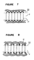
- Figures 1 and 2 show steps of a conventional method of manufacturing the armature and Figure 8 shows an important part of the conventional armature.
- a reference numeral 1 designates a coil element
- a numeral 10 designates a coil unit formed by winding in a circular form the coil element 1 in the number of turns required to form a single phase
- a numeral 20 designates a coil member formed by shaping the coil unit by using a shaping machine (not shown) into a ring form in which a plurality of raising and sinking portions are alternately formed in the radial direction.
- Figure 3 shows a stator core 2 provided with a number of slots 21.
- Figure 8 shows a part of a stator assembly 30, in a developed form, of the conventional armature, in which the coil members 20 are fitted in the slots of the stator core 2.
- a numeral 31 designates coil ends.
- the stator assembly 30 is formed by inserting each portion of the coil member 20 extending in the radial direction in each of the slots 21 of the stator core 2.
- coil ends 31 lead out from one slot are bundled together and have the same direction to be introduced another slot. Accordingly, when the coil member 20 is inserted in the slots 21 of the stator core 2 at a high occupation rate, it is difficult to insert the coil member 20 without increasing the height of projection of the coil ends 31 above a side surface of the stator core 2. Further, since the coil member constitutes a single phase, cooling property of the coil ends 31 is deteriorated.
- the present invention is to provide an armature of an a.c. generator for a car comprising a stator core provided with a number of slots and stator coils fitted in the slots, characterized in that about a half in number of coil elements of each radially extending portion of the stator coil received in the slots is received in the other slots.
- the present invention is to provide a method of manufacturing an armature of an a.c. generator for a car characterized in that a stator coil formed by shaping a coil element in a multi-wound ring-shape, in which a number of raising and sinking portions are alternately formed in the radial direction; is splitted into two multi-wound ring-shape stator coils with electrical connection between them; either one of the two multi-would ring-shape stator coils is 180° reversed; two splitted stator coils are overlapped so that each of the raising portions of either of the splitted stator coils corresponds to each of the sinking portions of the other splitted stator coils; and the splitted stator coils are fitted into slots formed in a stator core.
- FIG 4 shows splitted coil members 20a, 20b formed by splitting the coil member 20 at substantially the same proportion rate.
- Figure 5 shows a state that the splitted coil member 20b is 180° reversed in the same plane where the splitted coils 20a, 20b in Figure 4 are placed.
- Figure 6 shows a stator coil formed by overlapping the both splitted coils 20a, 20b as shown in Figure 5 so that the raising portion of the splitted coil 20a correspond to the sinking portions of the splitted coil 20b.
- Figure 7 is a diagram showing a stator assembly 35 formed by inserting the stator coil as shown in Figure 6 in the slots 21 of the stator core 2.
- the armature of the present invention is manufactured as follows.
- a single phase coil unit 10 is formed by winding in a ring form the coil element 1 in a requisite number of turns.
- the coil unit 10 is subjected to a shaping operation by using a shaping machine (not shown) to form a star-like coil member 20 as shown in Figure 2.
- the star-like coil member 20 is splitted into two splitted coils 20a, 20b in substantially the same proportion while the both splitted coils 20a, 20b are electrically connected.
- the splitted coil 20b is 180° reversed in the same plane as shown in Figure 5, and thereafter, the reversed coil 20b is overlaid on the splitted coil 20a so that each of the raised portions of the splitted coil 20b corresponds each of the sinking portions of the splitted coil 20a.
- a stator coil 40 as shown in Figure 6 is obtainable.
- the stator coil 40 is subjected to regulation of shape so that inner and outer circles formed by coil ends have substantially same center.
- the shape regulating operation provides easy insertion of the stator coil 40 into the slots 21 of the stator core 2.
- the other two stator coils 40 are formed and inserted in the slots of the stator core 2 in the same manner as described above.
- the armature as shown in Figure 7 can be obtained.
- the splitted coils 20a, 20b may be formed by splitting a ringed coil unit 10 into two parts, which follow by forming the splitted ringed coil parts to have a star-shape so that each of the raising portions of one splitted part corresponds to each of the sinking portions of the other splitted part.
- the armature obtained by the present invention about the portion of the coil elements of the stator coil, extending from the slots is divided into two parts, which are received in different slots. Accordingly, even when the stator coil is inserted in the slots at a high occupation rate, an inserting operations can be easy while the height of the coil ends can be reduced. Further, the coil ends can be effectively cooled.
Landscapes
- Engineering & Computer Science (AREA)
- Power Engineering (AREA)
- Manufacturing & Machinery (AREA)
- Windings For Motors And Generators (AREA)
- Manufacture Of Motors, Generators (AREA)
Applications Claiming Priority (2)
| Application Number | Priority Date | Filing Date | Title |
|---|---|---|---|
| JP156580/85 | 1985-07-15 | ||
| JP60156580A JPS6218952A (ja) | 1985-07-15 | 1985-07-15 | 車両用交流発電機の電機子の製造方法 |
Publications (3)
| Publication Number | Publication Date |
|---|---|
| EP0209091A2 true EP0209091A2 (fr) | 1987-01-21 |
| EP0209091A3 EP0209091A3 (en) | 1987-06-16 |
| EP0209091B1 EP0209091B1 (fr) | 1990-03-07 |
Family
ID=15630868
Family Applications (1)
| Application Number | Title | Priority Date | Filing Date |
|---|---|---|---|
| EP86109513A Expired - Lifetime EP0209091B1 (fr) | 1985-07-15 | 1986-07-11 | Procédé de fabrication d'une armature d'un générateur à courant alternatif pour véhicule |
Country Status (4)
| Country | Link |
|---|---|
| US (1) | US4857787A (fr) |
| EP (1) | EP0209091B1 (fr) |
| JP (1) | JPS6218952A (fr) |
| DE (1) | DE3669425D1 (fr) |
Cited By (7)
| Publication number | Priority date | Publication date | Assignee | Title |
|---|---|---|---|---|
| EP0455121A3 (en) * | 1990-04-26 | 1991-12-18 | Mitsubishi Denki Kabushiki Kaisha | Stator manufacturing method |
| DE9212889U1 (de) * | 1992-09-24 | 1994-01-27 | Siemens AG, 80333 München | Wicklungsanordnung für eine mehrphasige elektrische Maschine |
| US5372165A (en) * | 1992-12-30 | 1994-12-13 | Statomat Specialmaschinen Gmbh | Process and device for producing a wave winding, especially for rotary current generators |
| EP0818874A1 (fr) * | 1996-06-28 | 1998-01-14 | Polytool Srl | Dispositif et méthodes de formation et insertion de bobines à plusieurs lobes, constituantes les enroulements du stator d'un alternateur |
| WO1998025444A3 (fr) * | 1997-03-18 | 1998-08-20 | Polytool S R L | Procede et dispositif servant a constituer un enroulent a lobes multiples pour le stator d'un alternateur et enroulement obtenu |
| GB2355859A (en) * | 1999-10-28 | 2001-05-02 | Delphi Tech Inc | Electric generator rotor winding |
| FR2901925A1 (fr) * | 2006-06-06 | 2007-12-07 | Gerard Koehler | Procede pour elaborer un bobinage global a poles consequents en fil, pour un secteur angulaire d'un stator d'une machine a reluctance a entrefers cylindriques et a phases angulairement reparties |
Families Citing this family (25)
| Publication number | Priority date | Publication date | Assignee | Title |
|---|---|---|---|---|
| JPH0732554B2 (ja) * | 1987-05-26 | 1995-04-10 | 三菱電機株式会社 | 車両用交流発電機の固定子 |
| US5239220A (en) * | 1990-04-26 | 1993-08-24 | Mitsubishi Denki K.K. | Stator wedge and guide jig therefor |
| US5440221A (en) * | 1992-07-08 | 1995-08-08 | Benchmarg Microelectronics, Inc. | Method and apparatus for monitoring batttery capacity with charge control |
| DE19549180A1 (de) * | 1995-12-30 | 1997-07-03 | Bosch Gmbh Robert | Stator für elektrische Maschine |
| US5725431A (en) * | 1996-09-26 | 1998-03-10 | Dana Corporation | Thrust washer for universal joint having preloading thrust surfaces |
| DE19739353A1 (de) * | 1997-09-08 | 1999-03-18 | Elmotec Elektro Motoren Tech | Verfahren und Vorrichtung zur Herstellung einer verteilten Wellenwicklung |
| AU731628B2 (en) * | 1997-12-23 | 2001-04-05 | Robert Bosch Gmbh | Procedure and device for the manufacture of wave windings for electric motors |
| DE19817304B4 (de) * | 1997-12-23 | 2010-04-08 | Robert Bosch Gmbh | Verfahren und Vorrichtung zum Herstellen von Wellenwicklungen für elektrische Maschinen |
| JP3285534B2 (ja) * | 1998-04-08 | 2002-05-27 | 三菱電機株式会社 | 車両用交流発電機の固定子 |
| JP2001103721A (ja) * | 1999-09-30 | 2001-04-13 | Hitachi Ltd | 車両用交流発電機 |
| CN1069853C (zh) * | 1999-12-29 | 2001-08-22 | 武进市龙城精锻有限公司 | 汽车发电机用爪极成型工艺 |
| DE10119776A1 (de) | 2000-04-27 | 2001-11-08 | Denso Corp | Stator einer Drehfeldmaschine und Verfahren zu seiner Herstellung |
| JP3484407B2 (ja) * | 2000-11-24 | 2004-01-06 | 三菱電機株式会社 | 車両用交流発電機 |
| JP3484412B2 (ja) * | 2000-12-26 | 2004-01-06 | 三菱電機株式会社 | 車両用交流発電機およびその固定子の製造方法 |
| JP3561249B2 (ja) * | 2001-09-17 | 2004-09-02 | 三菱電機株式会社 | 交流発電機の固定子およびその製造方法 |
| JP2005124362A (ja) * | 2003-10-20 | 2005-05-12 | Toyota Industries Corp | 巻き線用ケーブル及び電機子 |
| WO2006067297A1 (fr) * | 2004-12-20 | 2006-06-29 | Valeo Equipements Electriques Moteur | Methode d’insertion d’un bobinage dans un stator de machine electrique tournante polyphasee, et stator associe |
| FR2888059B1 (fr) * | 2005-06-30 | 2007-09-07 | Valeo Equip Electr Moteur | Enroulement de phase pour un stator de machine electrique tournante et stator equipe d'un tel enroulement de phase |
| FR2896350B1 (fr) * | 2006-01-16 | 2008-02-29 | Valeo Equip Electr Moteur | Procede pour realiser le bobinage d'un stator de machine electrique tournante, et stator obtenu par ce procede |
| CA2767057A1 (fr) * | 2006-09-08 | 2008-03-13 | E-Max Gaming Corporation | Unite de jeu electronique sans fil |
| JP4234749B2 (ja) * | 2006-10-19 | 2009-03-04 | 株式会社日立製作所 | 回転電機、クランク形状の連続巻きコイル、分布巻き固定子及びそれらの形成方法 |
| JP2009303286A (ja) * | 2008-06-10 | 2009-12-24 | Aichi Elec Co | 電動機 |
| JP5394058B2 (ja) * | 2008-12-26 | 2014-01-22 | 株式会社小松製作所 | 電動機の電機子および電動機 |
| FR3062254B1 (fr) * | 2017-01-23 | 2019-06-07 | Valeo Equipements Electriques Moteur | Stator bobine pour machine electrique tournante |
| RU2746441C1 (ru) * | 2020-06-02 | 2021-04-14 | Сотис АГ | Громковоритель |
Family Cites Families (21)
| Publication number | Priority date | Publication date | Assignee | Title |
|---|---|---|---|---|
| GB1032345A (en) * | 1961-11-15 | 1966-06-08 | Lucas Industries Ltd | Dynamo electric machine windings |
| DE1563094B2 (de) * | 1965-04-13 | 1972-02-17 | Yasukawa, Futoshi, Kyoto (Japan) | Verfahren zur herstellung einer staenderwicklung fuer elektri sche motoren oder generatoren |
| US3479543A (en) * | 1967-12-11 | 1969-11-18 | Gen Electric | Compound excitation system |
| US3497730A (en) * | 1968-01-19 | 1970-02-24 | Clark Equipment Co | Rotary and linear polyphase motors having staggered field winding arrangements |
| DE2011201B2 (de) * | 1970-03-10 | 1975-01-02 | Breuer Elektronik Gmbh & Co Kg, 6901 Altenbach | Wicklung für elektrische Maschinen |
| JPS513041A (ja) * | 1974-06-25 | 1976-01-12 | Mitsubishi Electric Corp | Reidanbosochi |
| NL163075C (nl) * | 1976-07-12 | 1980-07-15 | Gils Adrianus Van | Gelamineerde wikkeling voor elektrische machines. |
| US4446393A (en) * | 1976-10-29 | 1984-05-01 | The Globe Tool & Engineering Company | Dynamoelectric field assembly and winding therefor |
| DE2921114A1 (de) * | 1979-05-25 | 1980-12-04 | Bosch Gmbh Robert | Wickelverfahren fuer einen elektrischen generator und danach hergestellter drehstromgenerator |
| SU855868A1 (ru) * | 1979-11-11 | 1981-08-15 | Горьковский политехнический институт им.А.А.Жданова | Совмещенна обмотка возбуждени синхронных машин |
| US4346320A (en) * | 1980-04-10 | 1982-08-24 | Westinghouse Electric Corp. | Dynamoelectric machine having improved interleaved stator end turns |
| FR2483702A1 (fr) * | 1980-05-30 | 1981-12-04 | Paris & Du Rhone | Procede et dispositif pour la realisation du bobinage d'un stator d'alternateur de petite puissance |
| DE3035136C2 (de) * | 1980-09-17 | 1984-05-30 | Siemens AG, 1000 Berlin und 8000 München | Mindestens zweisträngige Zweischicht-Runddrahtwicklung mit zusammenhängend gewickelten Spulengruppen |
| US4331896A (en) * | 1980-10-20 | 1982-05-25 | Sedgewick Richard D | Zig-zag windings, winding machine, and method |
| JPS57166834A (en) * | 1981-04-02 | 1982-10-14 | Toko Inc | Manufacture of coil for motor |
| US4426771A (en) * | 1981-10-27 | 1984-01-24 | Emerson Electric Co. | Method of fabricating a stator for a multiple-pole dynamoelectric machine |
| US4520287A (en) * | 1981-10-27 | 1985-05-28 | Emerson Electric Co. | Stator for a multiple-pole dynamoelectric machine and method of fabricating same |
| JPS5914336A (ja) * | 1982-07-14 | 1984-01-25 | Hitachi Ltd | 回転電気機械 |
| JPS59159638A (ja) * | 1983-03-01 | 1984-09-10 | Nippon Denso Co Ltd | 車両用交流発電機 |
| GB2150053B (en) * | 1983-11-24 | 1987-02-25 | Pavesi & C Spa Off Mec | Apparatus for forming stator coils of undulatory type for dynamo-electric machines |
| JPS619142A (ja) * | 1984-06-20 | 1986-01-16 | Hitachi Ltd | 3相交流発電機固定子の巻線方法 |
-
1985
- 1985-07-15 JP JP60156580A patent/JPS6218952A/ja active Granted
-
1986
- 1986-07-11 DE DE8686109513T patent/DE3669425D1/de not_active Expired - Lifetime
- 1986-07-11 EP EP86109513A patent/EP0209091B1/fr not_active Expired - Lifetime
-
1987
- 1987-11-23 US US07/124,261 patent/US4857787A/en not_active Expired - Lifetime
Cited By (9)
| Publication number | Priority date | Publication date | Assignee | Title |
|---|---|---|---|---|
| EP0455121A3 (en) * | 1990-04-26 | 1991-12-18 | Mitsubishi Denki Kabushiki Kaisha | Stator manufacturing method |
| DE9212889U1 (de) * | 1992-09-24 | 1994-01-27 | Siemens AG, 80333 München | Wicklungsanordnung für eine mehrphasige elektrische Maschine |
| US5372165A (en) * | 1992-12-30 | 1994-12-13 | Statomat Specialmaschinen Gmbh | Process and device for producing a wave winding, especially for rotary current generators |
| EP0604797A3 (en) * | 1992-12-30 | 1996-04-24 | Statomat Spezialmaschinen | Method and device for the production of a wave winding, in particular for three phase alternators. |
| EP0818874A1 (fr) * | 1996-06-28 | 1998-01-14 | Polytool Srl | Dispositif et méthodes de formation et insertion de bobines à plusieurs lobes, constituantes les enroulements du stator d'un alternateur |
| WO1998025444A3 (fr) * | 1997-03-18 | 1998-08-20 | Polytool S R L | Procede et dispositif servant a constituer un enroulent a lobes multiples pour le stator d'un alternateur et enroulement obtenu |
| EP1160957A1 (fr) * | 1997-03-18 | 2001-12-05 | Pavesi S.R.L. | Procédé et dispositif servant à constituer un enroulement à lobes multiples pour le stator d'un alternateur |
| GB2355859A (en) * | 1999-10-28 | 2001-05-02 | Delphi Tech Inc | Electric generator rotor winding |
| FR2901925A1 (fr) * | 2006-06-06 | 2007-12-07 | Gerard Koehler | Procede pour elaborer un bobinage global a poles consequents en fil, pour un secteur angulaire d'un stator d'une machine a reluctance a entrefers cylindriques et a phases angulairement reparties |
Also Published As
| Publication number | Publication date |
|---|---|
| JPH0442899B2 (fr) | 1992-07-14 |
| EP0209091A3 (en) | 1987-06-16 |
| EP0209091B1 (fr) | 1990-03-07 |
| US4857787A (en) | 1989-08-15 |
| JPS6218952A (ja) | 1987-01-27 |
| DE3669425D1 (de) | 1990-04-12 |
Similar Documents
| Publication | Publication Date | Title |
|---|---|---|
| EP0209091A2 (fr) | Procédé de fabrication d'une armature d'un générateur à courant alternatif pour véhicule | |
| EP0064105B1 (fr) | Stator d'un moteur électrique et son procédé de fabrication | |
| US6317962B1 (en) | Method for producing a stator of an alternating-current dynamo-electric machine | |
| US5113573A (en) | Stator manufacturing method | |
| US4829206A (en) | Armature for an electric rotary machine and method of manufacturing the same | |
| US3575623A (en) | Winding end turn insulator for a dynamoelectric machine | |
| US6389678B1 (en) | Method of constructing a salient pole motor | |
| US6742238B2 (en) | Flare tooth stator for an AC generator | |
| US20040256936A1 (en) | Armature of rotary electrical device | |
| US5182848A (en) | Method for assembling a stator subassembly | |
| US4176444A (en) | Method and apparatus for assembling dynamoelectric machine stators | |
| EP0570031B1 (fr) | Pièce d'extrémité statorique et méthode d'assemblage sur le stator | |
| US6949848B2 (en) | Terminal for armature | |
| US3440460A (en) | Laminated motor stator with formed coils and shaded poles and method of making | |
| US7726005B2 (en) | Method for making an electromagnetically excitable core of an electrical machine with a multiphase winding | |
| US4417388A (en) | Method of making a multiple open turn lap wound dynamoelectric machine | |
| US6141865A (en) | Winding method and winding apparatus for producing stators for electric motors | |
| US7084545B2 (en) | Electric machine and method of making an electric machine | |
| EP0976192B1 (fr) | Procedure de preparation et positionement des enroulements d'un moteur electrique | |
| JP3056738B1 (ja) | コンデンサ電動機固定子の製造方法 | |
| EP0107247A1 (fr) | Machine électrique | |
| US5099164A (en) | Stator end member winding support shroud | |
| US4267719A (en) | Apparatus for assembling dynamoelectric machine stators | |
| US5063315A (en) | Electrical coil connector for dynamoelectric machine windings | |
| AU2804889A (en) | Toroidally wound generator/motor |
Legal Events
| Date | Code | Title | Description |
|---|---|---|---|
| PUAI | Public reference made under article 153(3) epc to a published international application that has entered the european phase |
Free format text: ORIGINAL CODE: 0009012 |
|
| AK | Designated contracting states |
Kind code of ref document: A2 Designated state(s): DE FR GB |
|
| PUAL | Search report despatched |
Free format text: ORIGINAL CODE: 0009013 |
|
| AK | Designated contracting states |
Kind code of ref document: A3 Designated state(s): DE FR GB |
|
| 17P | Request for examination filed |
Effective date: 19870729 |
|
| 17Q | First examination report despatched |
Effective date: 19890130 |
|
| GRAA | (expected) grant |
Free format text: ORIGINAL CODE: 0009210 |
|
| AK | Designated contracting states |
Kind code of ref document: B1 Designated state(s): DE FR GB |
|
| REF | Corresponds to: |
Ref document number: 3669425 Country of ref document: DE Date of ref document: 19900412 |
|
| ET | Fr: translation filed | ||
| PLBE | No opposition filed within time limit |
Free format text: ORIGINAL CODE: 0009261 |
|
| STAA | Information on the status of an ep patent application or granted ep patent |
Free format text: STATUS: NO OPPOSITION FILED WITHIN TIME LIMIT |
|
| 26N | No opposition filed | ||
| REG | Reference to a national code |
Ref country code: GB Ref legal event code: IF02 |
|
| PGFP | Annual fee paid to national office [announced via postgrant information from national office to epo] |
Ref country code: GB Payment date: 20050706 Year of fee payment: 20 |
|
| PGFP | Annual fee paid to national office [announced via postgrant information from national office to epo] |
Ref country code: DE Payment date: 20050707 Year of fee payment: 20 |
|
| PGFP | Annual fee paid to national office [announced via postgrant information from national office to epo] |
Ref country code: FR Payment date: 20050708 Year of fee payment: 20 |
|
| REG | Reference to a national code |
Ref country code: GB Ref legal event code: PE20 |
|
| PG25 | Lapsed in a contracting state [announced via postgrant information from national office to epo] |
Ref country code: GB Free format text: LAPSE BECAUSE OF EXPIRATION OF PROTECTION Effective date: 20060710 |