EP0209117A2 - Fahrzeuglenksystem - Google Patents
Fahrzeuglenksystem Download PDFInfo
- Publication number
- EP0209117A2 EP0209117A2 EP86109699A EP86109699A EP0209117A2 EP 0209117 A2 EP0209117 A2 EP 0209117A2 EP 86109699 A EP86109699 A EP 86109699A EP 86109699 A EP86109699 A EP 86109699A EP 0209117 A2 EP0209117 A2 EP 0209117A2
- Authority
- EP
- European Patent Office
- Prior art keywords
- steering
- angle
- movement
- rear wheels
- wheels
- Prior art date
- Legal status (The legal status is an assumption and is not a legal conclusion. Google has not performed a legal analysis and makes no representation as to the accuracy of the status listed.)
- Granted
Links
- 230000007246 mechanism Effects 0.000 claims abstract description 40
- 230000004044 response Effects 0.000 claims description 4
- 238000010586 diagram Methods 0.000 description 5
- 230000006870 function Effects 0.000 description 3
- 230000009471 action Effects 0.000 description 1
- 230000008859 change Effects 0.000 description 1
- 230000001419 dependent effect Effects 0.000 description 1
- 230000004048 modification Effects 0.000 description 1
- 238000012986 modification Methods 0.000 description 1
- 230000007935 neutral effect Effects 0.000 description 1
Images


Classifications
-
- B—PERFORMING OPERATIONS; TRANSPORTING
- B62—LAND VEHICLES FOR TRAVELLING OTHERWISE THAN ON RAILS
- B62D—MOTOR VEHICLES; TRAILERS
- B62D7/00—Steering linkage; Stub axles or their mountings
- B62D7/06—Steering linkage; Stub axles or their mountings for individually-pivoted wheels, e.g. on king-pins
- B62D7/14—Steering linkage; Stub axles or their mountings for individually-pivoted wheels, e.g. on king-pins the pivotal axes being situated in more than one plane transverse to the longitudinal centre line of the vehicle, e.g. all-wheel steering
- B62D7/15—Steering linkage; Stub axles or their mountings for individually-pivoted wheels, e.g. on king-pins the pivotal axes being situated in more than one plane transverse to the longitudinal centre line of the vehicle, e.g. all-wheel steering characterised by means varying the ratio between the steering angles of the steered wheels
- B62D7/1518—Steering linkage; Stub axles or their mountings for individually-pivoted wheels, e.g. on king-pins the pivotal axes being situated in more than one plane transverse to the longitudinal centre line of the vehicle, e.g. all-wheel steering characterised by means varying the ratio between the steering angles of the steered wheels comprising a mechanical interconnecting system between the steering control means of the different axles
- B62D7/1545—Steering linkage; Stub axles or their mountings for individually-pivoted wheels, e.g. on king-pins the pivotal axes being situated in more than one plane transverse to the longitudinal centre line of the vehicle, e.g. all-wheel steering characterised by means varying the ratio between the steering angles of the steered wheels comprising a mechanical interconnecting system between the steering control means of the different axles provided with electrical assistance
Definitions
- the present invention relates to a vehicle steering system and more particularly to a so-called four-wheel steering system wherein fore and aft wheels are steered simultaneously. More specefically, the present invention pertains to control means for controlling the steering angle of the rear wheels in relation to the steering angle of the front wheels.
- a vehicle steering system including a front wheel steering mechanism for steering the front wheels and a rear wheel steering mechanism for steering the rear wheels wherein the rear wheel steering mechanism controls the steering ratio of the rear wheels to the front wheels in accordance with the vehicle speed.
- the rear wheel is steered in the opposite direction as the front wheel under a low speed vehicle operation and in the same direction under a high speed operation so as to facilitate the turning movement of the vehicle. It is alleged that with this control it is possible to minimize the turnig radius of the vehicle to thereby improve the maneuvability of the vehicle.
- the turning rate of the vehicle under a steering operation is dependent not only on the steering angle but also on the steering rate or the angular speed under which the steering wheel is moved. More specifically, there is a general tendency that the turning rate of the vehicle is increased as the steering rate is increased even when the steering angle is the same. It will therefore be understood that under a high steering rate, there is a tendency of oversteer and this tendency cannot be suppressed even with the control as proposed by the aforementioned U.S.Patent.
- Another object of the present invention is to provide a vehicle steering mechanism wherein the vehicle turning rate is determined irrespective of the steering rate, that is, the angular rate under which the steering wheel is steered.
- Another object of the present invention is to provide a vehicle steering mechanism by which a stable drivability can be obtained in the four-wheeled vehicles.
- a steering mechanism of a vehicle including front wheel steering means for steering front wheels of the vehicle, operating means for effecting a steering movement of said front wheel steering means to a desired angle, rear wheel steering means for steering rear wheels of said vehicle, steering angle control means for effecting a steering movement of said rear wheel steering means in relation to the steering movement of the front wheels, said steering angle control means including actuating means for moving said rear wheels to a desired steering angle of the rear wheels, CHARACTERIZED BY the fact that the vehicle further comprises steering rate detecting means for detecting a rate of the steering operation for said operating means and producing signals denoting the rate of the steering operation, and steering ratio changing means for changing a steering angle of the rear wheels based on the signals from the steering rate detecting means in such a manner that a steering angle ratio of said rear wheels to the steered angle of said front wheel is increased in the same direction as the steered direction of the front wheels as the rate of the steering operation increases.
- a vehicle steering system including a front wheel steering mechanism A which is adapted to steer a pair of front wheels 1R and 1L.
- the front wheel steering mechanism A is connected with an operating mechanism C including a steering wheel 9 and a rack-and-pinion mechanism which functions to convert a rotating movement of the steering wheel 9 into a linear movement.
- the rack and pinion mechanism is provided with rack 6 formed on the rod 5, and a pinion 7 in meshing engagement with the rack 6 in which the pinion 7 is connected to the steering wheel 9 through a shaft 8.
- the front wheel steering mechanism A further includes knucle arms 3R, 3L and tie-rods 4R, 4L interconnected by means of a rod 5 which transmit the linear movement of the rack-and-pinion mechanism to the front wheels 1R and 1L.
- the rod 5 moves in the left direction in the Figure 1 so that the knucle arms 3R, 3L and therefore the front wheels lR and lL are steered in the clockwise direction around rotating centers 3R'and 3L'in response to the amount of the operation of the steering wheel 9, that is, the steering angle.
- the front wheels 1R and 1L are similarly steered leftward.
- a rear wheel steering mechanism B which is adapted to steer a pair of rear wheels 2R and 2L.
- the steering mechanism B also includes a pair of knucle arms 10R and 10L, tie-rods 11R and 11L and a rod 12 for interconnecting the tie-rods 11R and 11L.
- the illustrated rear wheel steering mechanism B is further provided with a hydraulic power assist system D for obtaining a desirable movement of the rear steering mechanism B.
- the power assist system D is provided with a power cylinder 13 mounted on the rod 12. It will be noted that in Figure 1, the rod 11 is axially passed through the cylinder 13. In the cylinder 13, there is a piston 13d which is secured to the rod 11 and slidable in the cylinder 13 in the axial direction.
- the piston 13d divides the inside cavity of the cylinder 13 into a left chamber 13b and a rightchamber 13c.
- the chamber 13b and 13c are communicated with a control valve 16 through oil passages 14 and 15 respectively.
- the control valve 16 is connected to oil passages 18 and 19 extending from a reservoir 17.
- the oil passage 18 is connected to a oil pump 20( not shown) for supplying a hydraulic pressure.
- the control valve 16 is provided with a n input shaft 16a which functions as an input member of the power system D, and an output shaft 16b.
- the output shaft 16b is formed with a pinion 21 in meshing engagement with a rack 22 formed on the rod 12.
- the operating mechanism C is connected with the rear wheel steering mechanism B through the front wheel steering system A and a steering ratio changing device E.
- An intermediate rod 23 provided with a pinion 24 at the front end thereof extends forwardly from the steering ratio changing device E.
- the pinion 24 is brought into meshing engagement with the rack 25 formed on the rod 5 of the front steering system A.
- a moving rod 26 extending from the steering ratio changing device E is formed with a rack 27 in meshing engagement with a pinion 28 mounted on the input shaft 16a of the control valve 16.
- the above moving rod 26 of the steering ratio changing device E is slidably mounted on a vehicle body F along a line l,.
- the steering ratio changing device E is provided with a swingable arm 29 which is swingably mounted on a holder 30 at the base portion thereof by means of a pin 31.
- the holder 30 is rotatably mounted on the body F so as to rotate around a rotating axis 30a thereof in line with a line l 2 perpendicular to the line l 1 .
- the pin 31 is located at a point where the line l 1 intersects the line l z and extends in a direction at the right angle to the line 2 .
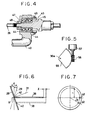
- FIG. 3 there is shown a connected portion of the holder 30 and the swingable arm 29 wherein the pin 31 is disposed within a U-shaped portion of the holder 30.
- the base portion of the arm 29 is rotatably engaged with the pin 31 through a pair of angular bearings 32.
- a guide member 33 and lock nut 34 are provided for securing the arm 29 to the bearing 32 and the pin 31.
- the arm 29 is swingable around the pin 31. It should however be noted that an angle between the pin 31 and the line l 1 , that is, between the pin 31 and a surface perpendicular to the line l 1 can be changed by rotating the holder 30.
- the swingable arm 29 is connected to the moving rod 26 at the tipend portion through a connecting member 38.
- the connecting member 38 including a rod 39 and an arm 40 is of a sufficient stiffness.
- the rod 39 is brought into meshing engagement with the arm 40 through a lock nut 41 so that the connecting member 38 is arranged for a desirable length.
- the connecting member 38 is connected to the swingable arm 29 at the front end of the rod 39 through a ball joint 42 and rotatably connected to the moving member 26 at the rear end portion of the arm 40 through a rotatable joint 43. Referreing to Figure 4, in the rotatable joint 42, the arm 40 is rotatably connected to the moving member 26 through a pair of angular bearings 44.
- a guide member 45 and a lock nut 46 are provided for securing the arm 40 to the angular bearings 44 .
- the arm 40 is of a arcuate member so as to avoid the interference with the moving member 26
- the rotatable joint 43 that is, a joint portion between the moving memvber 26 and the arm 40 is positioned on the extension line of the axis of the straight rod 39.
- the distance between the ball joint 42 located at the tip end of the swingable arm 29 and the rotatable joint 43 is maintained at a constant value by means of the connecting member 38. It is therefore understood that the moving member 26 is moved in the lateral direction in the Figure 2 in accordance with the movement of the ball joint 42 in the lateral direction.
- the swingable arm 29 is adapted to swing around the pin 31 in response to the steering movement of the operating mechanism C that is, the steering angle produced in the steering wheel 9.
- an actuating arm 49 is provided for the rod 39 of the connecting member 38.
- the actuating arm 49 including a main body 50 and a tip member 51 is rotatably mounted to the vehicle body F in such a manner that a rotation shaft 49a of the base portion of the main body 50 is positioned on the axis line l 1 .
- the tip member 51 is slidably engaged with the main body 50 in a direction perpendicular to the rotation shaft 49a and engaged at the tip end portion with the rod 39 of the connecting member 38 through a ball joint 52.
- a bevel gear 53 provided on the rotation shaft 49a of the actuating arm 49 is in meshing engagement with a bevel gear 54 mounted on the rear end of the intermediate rod 23. It will be understood that the ball joint 42 is moved along the line l 1 in the Figure 2 in accordance with the swingable movement of the arm 29 around the pin 31 in response to the amount of the steering movement of the steering wheel 9 since the axis of the pin 31 is inclined to the line l 1 so that the moving member 26 is moved through the connecting member 38.
- the amount of the lateral movement of the ball joint 42 is changed in accordance with the changes in the rotative angle of the holder 30, that is, the angle between the axis of the pin 31 and the line l 1 even when the swing angle of the arm 29 is constant.
- a sector gear 55 on the rotative shaft 30 of the holder 30 is brought into meshing engagement with a worm gear 56 which is driven by an actuator including a solenoid, a pulse motor and the like.
- the rotative angle of the holder 30, that is, the angle of the axis of the pin 31 to the line l 1 is detected by means of a steering angle ratio detector 58 (shown in the Figure 1).
- a battery 59 As shown in Figure 1, there is provided a battery 59.
- FIG. 6 and Figure 7 there is shown a schematic view of the relationship between the angle of the axis of the pin 31 to the line l 1 and the amount of the movement of the ball joint 42 in the rateral direction.
- the swing angle of the arm 29 around the pin 31 is denoted by ⁇ .
- a plane perpendicular to the line l 1 , the angle between the plane and the plane of the swing orbit of the arm and the distance between the pin 31 and the ball joint 42 are denoted by ⁇ , ⁇ , and r respectively.
- the movement X of the ball joint 42 is a function of the angle ⁇ that is, the steering angle when the angle ⁇ is constant while the amount X is changed under the contsant steering angle when the angle ⁇ is changed.
- the change of the angle ⁇ changes the steering angle ratio.
- the steering angle ratio can be controlled by means of a control of the angle ⁇ as shown in Figure 8.
- the steering angle ratio is changed in accordace with the vehicle speed.
- the real line Sl denotes a property of the steering angle ratio in which the rate of the steering operation as produced in an usual operation is relatively low.
- the dotted line S2 denotes a property of the steering angle ratio in which the rate of the steering operation is high.
- the rear wheels 2R and 2L is steered in the direction oppsite to the direction as the front wheels is steered under low vehicle speed operation such as garaging so that the vehicle can be smoothly led to the garage. While, the rear wheels 2R and 2L is steered in the same direction as the direction of the front wheels 1R and lL under high vehicle speed operation such as running in the express highway so that the running zone of the vehicle can be quickly changed.
- the property S2 is determined in such a manner that it takes lager positive values in comparison with the property Sl as the rate of the steering operation for the steering wheel 9 is increased.
- an electronic control unit 61 which controls the steering angle of the rear wheels 2R and 2L based on the property Sl or S2.
- the control unit 61 receives signals from the steering angle ratio detector 58, signals from a vehicle speed sensor 62 and signals from a steering rate sensor 63 for detecting the rate of the steering operation for the steering wheel 9.
- the control unit 61 produces signals for the actuator 57. It will be noted that the rate of the steering operation for the steering wheel 9 may be obtained by detecting the rotation speed of the steering wheel 9, the moving speed of the rod 5 or the like.
- the control unit 61 includes a desired steering angle calculating circuit 73 which receives the signals from the sensor 62 and a selecting circuit 72 which receives signals from the steering rate sensor 63 so as to detenrme a desirable steering angle ratio property among the properties as shown in the Figure 8 in accordance with the rate of the steering operation.
- the calculating circuit 73 is connected with a memory 71 which mimorizes steering angle ratio properties Sl and S2 between the steering angle of the rear wheels 2R and 2L and steering angle of the front wheels 1R and 1L.
- the output of the calculating circuit 73 is connected with a pulse genetator 74 which produces pulse signals corresponding to the output of the calculating circuit 73.
- the output of the pulse generator 32 is connected with a motor driving circuit 75 which produces signals for actuating the actuator 57.
- the selecting circuit 72 of the control unit 61 determines a desired steering angle ratio properties of the rear wheels among the properties memorized in the memory 71 based on the steered rate signal from the sensor 63.
- the calculating circuit 73 then calculates a desirable steering angle ratio of the rear wheels 2R and 2L to the front wheels lR and 1L based on the steering angle ratio property selected by the selecting circuit 72 in accordance with the vehicle speed.
- the signals from the calculating circuit 73 is applied to the pulse generator 74 , to the driving circuit 75 ,in turn to the actuator 57 as a pulse motor so that the actuator 57 is driven to provide a desirable steering angle of the rear wheels 2R and 2L.
- a feedback control may be adopted making use of the steering angle ratio detector 58 in order to reduce the amount of an error between the steering angle based on the above calculated steering angle ratio.
- the rear wheels 2R and 2L are steered in accordance with the property Sl under slow steering operation for the steering wheel 9, while in accordance with the property S2 under quick steering operation.
- FIG 11 shows another embodiment of the control unit 61.
- This control unit 61 is provided with a calculating circuit 81 which receives signals from the vehicle speed sensor 62.
- the calculating circuit 81 calculates a desirable steering angle ratio of the rear wheels 2R and 2L to the front wheels 1R and 1L based on the property S1.
- the value of the steering angle ratio calculated in the calculating circuit 81 is then compensated based on the property S2 by means of a compensating circuit 82 which receives the signals from the steering rate sensor 63.
- the actuator 57 is driven in accordance with the output of the compensating circuit 82 through a pulse generator 83 and a driving circuit 84 to thereby cause the steering movement of the rear wheels 2R and 2L.
- Figure 9 shows steering angle ratio properteis wherein the steering angle of the rear wheels 2R and 2L is determined based on the steering angle of the front wheels 1R and 1L inste.ad of the vehicle speed described in reference to the Figure 8.
- the property S2 corresponding to the quick steering operation for the steering wheels 9 takes larger positive values in comparison with the property S1 corresponding to the slow steering operation.
- a sensor may be utilized for detecting the steering angle of the front wheels in lieu of the vehicle speed sensor as shown in the Figure 10 and Figure 11. It will be understood that the steering angle of the front wheels can be obtained by detecting the amount of the rotation angle of the steering wheel 9 or the movement of the rod 5.
- FIG. 12 there is shown another embodiment of the four-wheeled vehicle in accordance with the present invention.
- the front wheel steering mechanism A (the operating mechanism C) is connected with the rear wheel steering mechanism B by not mechanical means but electrical means unlike the aforementioned embodiment.
- the pinion 21 is brought in meshing engagement with the rack 22 formed on the rod 12 as well as in the embodiment of the Figure 1.
- the pinion is however driven by the actuator 57 of a pulse motor through a pair of bevel gears 91, 92.
- the actuator 57 is adapted to be controlled by the control unit 61.
- the control unit receives signals from the steering rate sensor 63, the steering angle sensor 64 for the front wheels and, if desired, ( in the case where the rear wheel steering angle is controlled in accordance with the properties as shown in the Figure 8 ) the vehicle speed sensor 64.
- a drive shaft 21a of the pinion 21 which corresponds to the input shaft 16a and output shaft 16b in the Figure 1 is connected to the control valve for the power assist system D.
- the hydraulic pump 20 is driven by electrical signals from the control unit 61 when the actuator 57 is actuated.
- the steering angle of the rear wheels 2R and 2L may be controlled in such a manner that the steering angle of the rear wheels 2R and 2L increases in the same direction as the steered direction of the front wheels 1R and lL in accordance with an increase of the rate of the steeting operation for the steering wheel.
Landscapes
- Engineering & Computer Science (AREA)
- Chemical & Material Sciences (AREA)
- Combustion & Propulsion (AREA)
- Transportation (AREA)
- Mechanical Engineering (AREA)
- Steering-Linkage Mechanisms And Four-Wheel Steering (AREA)
- Steering Control In Accordance With Driving Conditions (AREA)
Applications Claiming Priority (2)
| Application Number | Priority Date | Filing Date | Title |
|---|---|---|---|
| JP60156935A JPS6218367A (ja) | 1985-07-18 | 1985-07-18 | 車両の4輪操舵装置 |
| JP156935/85 | 1985-07-18 |
Publications (3)
| Publication Number | Publication Date |
|---|---|
| EP0209117A2 true EP0209117A2 (de) | 1987-01-21 |
| EP0209117A3 EP0209117A3 (en) | 1987-07-22 |
| EP0209117B1 EP0209117B1 (de) | 1990-02-07 |
Family
ID=15638564
Family Applications (1)
| Application Number | Title | Priority Date | Filing Date |
|---|---|---|---|
| EP86109699A Expired EP0209117B1 (de) | 1985-07-18 | 1986-07-15 | Fahrzeuglenksystem |
Country Status (4)
| Country | Link |
|---|---|
| US (1) | US4805939A (de) |
| EP (1) | EP0209117B1 (de) |
| JP (1) | JPS6218367A (de) |
| DE (1) | DE3668861D1 (de) |
Cited By (3)
| Publication number | Priority date | Publication date | Assignee | Title |
|---|---|---|---|---|
| EP0280207A3 (en) * | 1987-02-20 | 1990-02-21 | Mazda Motor Corporation | Four-wheel steering for vehicle and method of incorporating same |
| EP0397324A1 (de) * | 1989-05-08 | 1990-11-14 | General Motors Corporation | Hinterradlenkwinkel-Steuerungsverfahren |
| DE4110107A1 (de) * | 1990-03-28 | 1991-10-02 | Nissan Motor | Hinterradlenksystem fuer ein kraftfahrzeug |
Families Citing this family (15)
| Publication number | Priority date | Publication date | Assignee | Title |
|---|---|---|---|---|
| JP2527194B2 (ja) * | 1987-07-29 | 1996-08-21 | 本田技研工業株式会社 | 前後輪操舵装置 |
| JP2694554B2 (ja) * | 1988-02-25 | 1997-12-24 | 富士重工業株式会社 | 自動車の後輪操舵制御方法 |
| JP2742687B2 (ja) * | 1988-02-25 | 1998-04-22 | 富士重工業株式会社 | 自動車の後輪操舵制御方法 |
| JPH01249578A (ja) * | 1988-03-31 | 1989-10-04 | Mazda Motor Corp | 車両の後輪操舵装置 |
| JP2549709B2 (ja) * | 1988-07-05 | 1996-10-30 | 日産自動車株式会社 | 4輪操舵車両の後輪操舵装置 |
| DE3836020A1 (de) * | 1988-09-07 | 1990-03-15 | Daimler Benz Ag | Allradlenkung fuer kraftfahrzeuge |
| JP2718098B2 (ja) * | 1988-10-06 | 1998-02-25 | 日本精工株式会社 | 四輪操舵装置 |
| JP2961736B2 (ja) * | 1988-10-06 | 1999-10-12 | 日本精工株式会社 | 四輪操舵装置 |
| JP2863922B2 (ja) * | 1988-11-28 | 1999-03-03 | マツダ株式会社 | 後輪操舵車両の後輪懸架装置 |
| JP2825831B2 (ja) * | 1989-01-18 | 1998-11-18 | マツダ株式会社 | 車両の後輪操舵装置 |
| US5226499A (en) * | 1989-02-28 | 1993-07-13 | Mazda Motor Corporation | Front and rear wheel turning system for vehicle |
| JPH0647386B2 (ja) * | 1990-06-15 | 1994-06-22 | マツダ株式会社 | 車両の4輪操舵装置 |
| JPH0549436U (ja) * | 1991-12-13 | 1993-06-29 | 三菱自動車エンジニアリング株式会社 | ドアセンタサッシュ取付け装置 |
| US6705421B2 (en) | 2002-05-31 | 2004-03-16 | Visteon Global Technologies, Inc. | Assisted steering system with out-of-phase driver and assist pinions |
| CN104960572B (zh) * | 2015-07-08 | 2017-08-25 | 武汉理工大学 | 具有四轮转向的商用车 |
Family Cites Families (5)
| Publication number | Priority date | Publication date | Assignee | Title |
|---|---|---|---|---|
| JPS6044185B2 (ja) * | 1978-12-29 | 1985-10-02 | 本田技研工業株式会社 | 車両の操舵方法及びその装置 |
| JPS60161260A (ja) * | 1984-01-31 | 1985-08-22 | Nissan Motor Co Ltd | 車両操舵装置 |
| US4572316A (en) * | 1984-03-15 | 1986-02-25 | Mazda Motor Corporation | Four-wheel steering system for vehicle |
| US4706771A (en) * | 1985-01-31 | 1987-11-17 | Nissan Motor Co., Ltd. | Vehicle steering control system using desired vehicle model |
| JP2575618B2 (ja) * | 1985-04-25 | 1997-01-29 | 株式会社豊田中央研究所 | 車両の後輪舵角制御装置 |
-
1985
- 1985-07-18 JP JP60156935A patent/JPS6218367A/ja active Pending
-
1986
- 1986-07-15 EP EP86109699A patent/EP0209117B1/de not_active Expired
- 1986-07-15 DE DE8686109699T patent/DE3668861D1/de not_active Expired - Fee Related
-
1987
- 1987-06-30 US US07/068,723 patent/US4805939A/en not_active Expired - Lifetime
Cited By (4)
| Publication number | Priority date | Publication date | Assignee | Title |
|---|---|---|---|---|
| EP0280207A3 (en) * | 1987-02-20 | 1990-02-21 | Mazda Motor Corporation | Four-wheel steering for vehicle and method of incorporating same |
| EP0397324A1 (de) * | 1989-05-08 | 1990-11-14 | General Motors Corporation | Hinterradlenkwinkel-Steuerungsverfahren |
| DE4110107A1 (de) * | 1990-03-28 | 1991-10-02 | Nissan Motor | Hinterradlenksystem fuer ein kraftfahrzeug |
| US5186273A (en) * | 1990-03-28 | 1993-02-16 | Nissan Motor Co., Ltd. | Rear wheel steering system for automotive vehicle |
Also Published As
| Publication number | Publication date |
|---|---|
| US4805939A (en) | 1989-02-21 |
| EP0209117A3 (en) | 1987-07-22 |
| EP0209117B1 (de) | 1990-02-07 |
| DE3668861D1 (de) | 1990-03-15 |
| JPS6218367A (ja) | 1987-01-27 |
Similar Documents
| Publication | Publication Date | Title |
|---|---|---|
| US4572316A (en) | Four-wheel steering system for vehicle | |
| US4805939A (en) | Vehicle steering system | |
| US4601357A (en) | Four-wheel steering system for vehicle | |
| US4941542A (en) | Automotive four wheel steering system | |
| US5341294A (en) | Four-wheel steering system for vehicle | |
| US5400250A (en) | Rear wheel steering device | |
| JPH0211479A (ja) | 前後輪操舵車の後輪操舵制御装置 | |
| US4792007A (en) | Mechanism for steering front and rear wheels of four-wheel vehicle | |
| JPS59128053A (ja) | 車両の4輪操舵装置 | |
| JPH05272B2 (de) | ||
| JPH0526716B2 (de) | ||
| JP2528460B2 (ja) | 車両の4輪操舵装置 | |
| JPH0525709B2 (de) | ||
| JPH078653B2 (ja) | 車両の4輪操舵装置 | |
| JPH01136876A (ja) | 4輪操舵装置 | |
| JPH0679901B2 (ja) | 車両の4輪操舵装置 | |
| JPH05330444A (ja) | 車両の4輪操舵装置 | |
| JPH0679902B2 (ja) | 車両の4輪操舵装置 | |
| JPH0679899B2 (ja) | 車両の4輪操舵装置 | |
| JPH0155146B2 (de) | ||
| JP2503540B2 (ja) | 4輪操舵車両の油圧式後輪舵取機構 | |
| JPH0557949B2 (de) | ||
| JPS62227870A (ja) | 車両の4輪操舵装置 | |
| JPH03121978A (ja) | 舵角制御機構 | |
| JPS63192663A (ja) | 車両の4輪操舵装置 |
Legal Events
| Date | Code | Title | Description |
|---|---|---|---|
| PUAI | Public reference made under article 153(3) epc to a published international application that has entered the european phase |
Free format text: ORIGINAL CODE: 0009012 |
|
| AK | Designated contracting states |
Kind code of ref document: A2 Designated state(s): DE FR GB |
|
| PUAL | Search report despatched |
Free format text: ORIGINAL CODE: 0009013 |
|
| AK | Designated contracting states |
Kind code of ref document: A3 Designated state(s): DE FR GB |
|
| 17P | Request for examination filed |
Effective date: 19870904 |
|
| 17Q | First examination report despatched |
Effective date: 19880229 |
|
| GRAA | (expected) grant |
Free format text: ORIGINAL CODE: 0009210 |
|
| AK | Designated contracting states |
Kind code of ref document: B1 Designated state(s): DE FR GB |
|
| REF | Corresponds to: |
Ref document number: 3668861 Country of ref document: DE Date of ref document: 19900315 |
|
| ET | Fr: translation filed | ||
| PLBE | No opposition filed within time limit |
Free format text: ORIGINAL CODE: 0009261 |
|
| STAA | Information on the status of an ep patent application or granted ep patent |
Free format text: STATUS: NO OPPOSITION FILED WITHIN TIME LIMIT |
|
| 26N | No opposition filed | ||
| PGFP | Annual fee paid to national office [announced via postgrant information from national office to epo] |
Ref country code: GB Payment date: 19960708 Year of fee payment: 11 |
|
| PGFP | Annual fee paid to national office [announced via postgrant information from national office to epo] |
Ref country code: FR Payment date: 19960709 Year of fee payment: 11 |
|
| PGFP | Annual fee paid to national office [announced via postgrant information from national office to epo] |
Ref country code: DE Payment date: 19960722 Year of fee payment: 11 |
|
| PG25 | Lapsed in a contracting state [announced via postgrant information from national office to epo] |
Ref country code: GB Free format text: LAPSE BECAUSE OF NON-PAYMENT OF DUE FEES Effective date: 19970715 |
|
| GBPC | Gb: european patent ceased through non-payment of renewal fee |
Effective date: 19970715 |
|
| PG25 | Lapsed in a contracting state [announced via postgrant information from national office to epo] |
Ref country code: FR Free format text: LAPSE BECAUSE OF NON-PAYMENT OF DUE FEES Effective date: 19980331 |
|
| PG25 | Lapsed in a contracting state [announced via postgrant information from national office to epo] |
Ref country code: DE Free format text: LAPSE BECAUSE OF NON-PAYMENT OF DUE FEES Effective date: 19980401 |
|
| REG | Reference to a national code |
Ref country code: FR Ref legal event code: ST |