EP0209305A2 - Verfahren und Vorrichtung zur Herstellung von Schrauben mit einem Bohr- und einem Räumabschnitt - Google Patents
Verfahren und Vorrichtung zur Herstellung von Schrauben mit einem Bohr- und einem Räumabschnitt Download PDFInfo
- Publication number
- EP0209305A2 EP0209305A2 EP19860305236 EP86305236A EP0209305A2 EP 0209305 A2 EP0209305 A2 EP 0209305A2 EP 19860305236 EP19860305236 EP 19860305236 EP 86305236 A EP86305236 A EP 86305236A EP 0209305 A2 EP0209305 A2 EP 0209305A2
- Authority
- EP
- European Patent Office
- Prior art keywords
- section
- reamer
- drill
- shaping
- drill section
- Prior art date
- Legal status (The legal status is an assumption and is not a legal conclusion. Google has not performed a legal analysis and makes no representation as to the accuracy of the status listed.)
- Granted
Links
Images


Classifications
-
- B—PERFORMING OPERATIONS; TRANSPORTING
- B23—MACHINE TOOLS; METAL-WORKING NOT OTHERWISE PROVIDED FOR
- B23G—THREAD CUTTING; WORKING OF SCREWS, BOLT HEADS, OR NUTS, IN CONJUNCTION THEREWITH
- B23G1/00—Thread cutting; Automatic machines specially designed therefor
-
- B—PERFORMING OPERATIONS; TRANSPORTING
- B21—MECHANICAL METAL-WORKING WITHOUT ESSENTIALLY REMOVING MATERIAL; PUNCHING METAL
- B21K—MAKING FORGED OR PRESSED METAL PRODUCTS, e.g. HORSE-SHOES, RIVETS, BOLTS OR WHEELS
- B21K1/00—Making machine elements
- B21K1/56—Making machine elements screw-threaded elements
Definitions
- the present invention relates to method and apparatus for making screws having a reamer section and drill section, the screw functioning as a drill screw as well as a reamer.
- the screw referred to in this specification means this type of screw unless specified to the contrary.
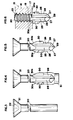
- first material 37 When a first material 37 is to be jointed to a second material 38, such as a structure constituted by a metal panel, holes 39 are first bored by the drill section 34 and the reamer edges 36 in the first material 37.
- the hole 39 is free from the thread section as best shown in Figures 14(b) and 15(b). If the hole is not present and the thread section is forced into the first material, the two plates will become separated because of the difference between the speed at which the drill section 34 makes a hole in the second metal material and the speed at which the thread section 33 advances in the first material 37.
- the reamer edges 36 are constructed so that they fracture when they come into contact with the second material 38 with which the thread section 33 are to be engaged in the second material 38.
- the first step is that the reamer edges 36 are shaped by means of a pinch pointing machine or any other press. This means that the conventional process requires an increased number of steps.
- the screw (A) illustrated in Figure 14 has no chip-discharge groove in its shank (e), thereby causing a choking problem due to the deposit of chips from the first material 37 cut by the drilling edges. This prevents the smooth boring through the first material 37.
- the screws (B) and (C) in Figures 15 and 16 have been devised so as to solve the problems pointed out with respect to the screw (A). They have reamer edges 36 in the land of the drill section, but the position of the reamer edges 36 is restricted in the peripheral direction. In forming the reamer edges 36 it is difficult to locate them in the restricted area. This leads to an inefficient production of screws and an increased production cost, thereby discouraging the wide use of the screws.
- a method for shaping screws having a drill section and a reamer section which method comprises:
- an apparatus for shaping screws having a drill section and a reamer section which apparatus comprises:
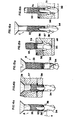
- Figures 1 and 2 show dies 1 and 1' for forming a drill section 24 and a reamer section 30.
- the dies are provided in pair, wherein the die for shaping the drill section 24 is substantially disclosed in Japanese Patent Publication (examined) No. 59-7046 (U.S. Patent No. 4,407,620).
- This die has two reference faces 2 and 3, which are in parallel with each other but one is slightly withdrawn from the other one.
- a recess 4 is produced with reference to the face 2, so as to shape a land 25 in the drill section 24, and a projection 25 is formed with reference to the face 3, so as t 6 produce a chip-discharge groove 26.
- the die also has edges 6 and 7 on the face 2, which define a top cutting lip 21 and a side cutting lip 28 of the screw, respectively.
- the die is provided with edges 6' and 7' on the face 3, which define another top cutting lip 27 and side cutting lip 28 of the screw, respectively.
- the die is provided with a third edge 8 for shaping a chisel edge 29, wherein the third edge 8 is defined by a line connecting between the lower parts of the edges 6 and 6'.
- a recess 10 in the face 2 so as to produce the reamer section 30, the recess 10 extending axially along the end edge 7, and projecting radially up to the maximum diameter of a thread section 23 of the screw or beyond it.
- the lower end 11 of the recess 10 is limited to a point axially spaced from the outermost part of the end edge 6 by a distance (h) (this distance is determined in accordance with the thickness of the second material 38), whereas its upper part is open up to the space 9 and the top face of the die.
- the thickness of the reamer section 30 is determined in accordance with the depth of the recess 10 (vertical tc the face 2).
- the rolling die 15 has a thread-forming section 16 and a crushing section 17 whereby the upper portions of the reamer sections 30 are crushed and aligned with an equal thickness and length, thereby ensuring that an equal fragility is imparted to the reamer sections 30.
- the reamer sections 30 are unified in the thickness and length of their root portions, which sections are formed along the edges 28 of the drill section 24.
- the rolling die 15 has the thread-forming section 16 and the crushing section 17 constructed in one-piece, but it is possible to divide them into two separate parts along the dotted lines 18 in Figure 6.
- Figures 10 to 13 inclusive show a pair of modified dies 1 and 1', which are distinguished from the first-mentioned pair in that the position of the upper end 12 of the recess 10 is specified at a position determined in accordance at the length of the reamer section 30 to be shaped, and is not open up to the upper surface of the die.
- the recess 10 is produced in the reference face 2, and in the reference face 3 a recess 13 is provided, which communicates with the recess 10 and is open up to the upper surface of the die.
- a step 14 is formed in the border between the reamer section 30 and its elongated portion 30a, which step is relatively thin.
- the elongated portion 30a has only to be crushed along the step 14, thereby ensuring that the lengths of the reamer sections 30 are made equal.
Landscapes
- Engineering & Computer Science (AREA)
- Mechanical Engineering (AREA)
- Forging (AREA)
- Milling, Broaching, Filing, Reaming, And Others (AREA)
Applications Claiming Priority (2)
| Application Number | Priority Date | Filing Date | Title |
|---|---|---|---|
| JP154431/85 | 1985-07-12 | ||
| JP60154431A JPS6216835A (ja) | 1985-07-12 | 1985-07-12 | リ−マ付きドリルねじの製造方法及び製造装置 |
Publications (3)
| Publication Number | Publication Date |
|---|---|
| EP0209305A2 true EP0209305A2 (de) | 1987-01-21 |
| EP0209305A3 EP0209305A3 (en) | 1988-07-27 |
| EP0209305B1 EP0209305B1 (de) | 1990-09-26 |
Family
ID=15584030
Family Applications (1)
| Application Number | Title | Priority Date | Filing Date |
|---|---|---|---|
| EP86305236A Expired - Lifetime EP0209305B1 (de) | 1985-07-12 | 1986-07-07 | Verfahren und Vorrichtung zur Herstellung von Schrauben mit einem Bohr- und einem Räumabschnitt |
Country Status (7)
| Country | Link |
|---|---|
| US (1) | US4722107A (de) |
| EP (1) | EP0209305B1 (de) |
| JP (1) | JPS6216835A (de) |
| KR (1) | KR940007169B1 (de) |
| AU (1) | AU570850B2 (de) |
| CA (1) | CA1272006A (de) |
| DE (1) | DE3674492D1 (de) |
Cited By (1)
| Publication number | Priority date | Publication date | Assignee | Title |
|---|---|---|---|---|
| EP0414973A1 (de) * | 1989-09-01 | 1991-03-06 | Gem Machinery Ind Co. Ltd. | Matrizenset zum schmieden der Schneidkante einer gewinneschneidenden Schraube |
Families Citing this family (8)
| Publication number | Priority date | Publication date | Assignee | Title |
|---|---|---|---|---|
| US4881395A (en) * | 1988-06-21 | 1989-11-21 | Yugen Kaisha Shinjo Seisakusho | Process and apparatus for fabricating stepped nails |
| US5046905A (en) * | 1989-07-06 | 1991-09-10 | Emhart Inc. | Winged drill screw |
| JPH0947833A (ja) * | 1995-08-08 | 1997-02-18 | Tsuda Kogyo Kk | 管継手ボルトの製造方法 |
| SE9700300D0 (sv) * | 1997-01-31 | 1997-01-31 | Astra Ab | Reamer |
| KR100359402B1 (ko) * | 1999-11-30 | 2002-11-04 | 임정환 | 드릴스크류 가공장치 |
| ITVR20030108A1 (it) * | 2003-09-09 | 2005-03-10 | Amafa Service S R L | Procedimento per l'estrusione a freddo di viti, in particolare per |
| DE102007048821A1 (de) * | 2007-10-10 | 2009-04-16 | Robert Bosch Gmbh | Werkzeugsystem |
| JP3169707U (ja) * | 2011-06-02 | 2011-08-11 | ニチハ株式会社 | 固定具 |
Family Cites Families (11)
| Publication number | Priority date | Publication date | Assignee | Title |
|---|---|---|---|---|
| US1913143A (en) * | 1931-02-24 | 1933-06-06 | Peter L Robertson | Means for roll-threading and pointing screws |
| US3395603A (en) * | 1966-09-13 | 1968-08-06 | Parker Kaion Corp | Rotary threaded fasteners |
| US3550255A (en) * | 1968-07-05 | 1970-12-29 | Parker Kalon Corp | Method of making rotary threaded fasteners |
| US3683436A (en) * | 1970-01-22 | 1972-08-15 | Textron Inc | Method for making a drill screw with an extruded point |
| US3747143A (en) * | 1971-04-07 | 1973-07-24 | Star Expansion Ind Corp | Screw formation |
| US3827331A (en) * | 1972-11-01 | 1974-08-06 | Res Eng & Mfg | Self-extruding screw |
| AU475406B2 (en) * | 1973-07-18 | 1976-01-08 | W. A. Deutsher Proprietary Limited | Self drilling screws |
| US4347027A (en) * | 1976-03-29 | 1982-08-31 | Illinois Tool Works Inc. | Drill screw |
| US4147088A (en) * | 1977-03-16 | 1979-04-03 | Nl Industries, Inc. | Drill screw |
| JPS597046B2 (ja) * | 1979-12-29 | 1984-02-16 | 有限会社新城製作所 | ドリルねじ |
| JPS58152919A (ja) * | 1982-03-04 | 1983-09-10 | マックス株式会社 | リ−マ−付きドリルネジ |
-
1985
- 1985-07-12 JP JP60154431A patent/JPS6216835A/ja active Granted
-
1986
- 1986-06-23 US US06/877,565 patent/US4722107A/en not_active Expired - Lifetime
- 1986-06-27 CA CA000512725A patent/CA1272006A/en not_active Expired - Fee Related
- 1986-07-02 AU AU59492/86A patent/AU570850B2/en not_active Ceased
- 1986-07-07 EP EP86305236A patent/EP0209305B1/de not_active Expired - Lifetime
- 1986-07-07 DE DE8686305236T patent/DE3674492D1/de not_active Expired - Lifetime
- 1986-07-11 KR KR1019860005605A patent/KR940007169B1/ko not_active Expired - Fee Related
Cited By (1)
| Publication number | Priority date | Publication date | Assignee | Title |
|---|---|---|---|---|
| EP0414973A1 (de) * | 1989-09-01 | 1991-03-06 | Gem Machinery Ind Co. Ltd. | Matrizenset zum schmieden der Schneidkante einer gewinneschneidenden Schraube |
Also Published As
| Publication number | Publication date |
|---|---|
| US4722107A (en) | 1988-02-02 |
| KR940007169B1 (ko) | 1994-08-08 |
| DE3674492D1 (de) | 1990-10-31 |
| KR870000990A (ko) | 1987-03-10 |
| CA1272006A (en) | 1990-07-31 |
| JPS6216835A (ja) | 1987-01-26 |
| EP0209305B1 (de) | 1990-09-26 |
| EP0209305A3 (en) | 1988-07-27 |
| JPH0516930B2 (de) | 1993-03-05 |
| AU5949286A (en) | 1987-01-15 |
| AU570850B2 (en) | 1988-03-24 |
Similar Documents
| Publication | Publication Date | Title |
|---|---|---|
| EP0561957B1 (de) | Kaltgeschmiedeter bohrmeissel mit zentraler absaugung | |
| US6089337A (en) | Drilling and/or chiseling tool | |
| US4407620A (en) | Drill screw | |
| US4033003A (en) | Head forming method | |
| US3463045A (en) | Drilling screw | |
| US4781506A (en) | Self-drilling screw | |
| IL28549A (en) | Rotary threaded fastener and method of making same | |
| US3241426A (en) | Drilling and tapping screw with ragged cutting edges | |
| EP0209305A2 (de) | Verfahren und Vorrichtung zur Herstellung von Schrauben mit einem Bohr- und einem Räumabschnitt | |
| US2886081A (en) | Drill elements | |
| US3550255A (en) | Method of making rotary threaded fasteners | |
| US2846902A (en) | Drill elements | |
| EP0538486B1 (de) | Nähmaschinenadel und Herstellungsverfahren | |
| IE810894L (en) | Forging drill bit shanks | |
| GB2335878A (en) | A thread milling cutter with drilling edges | |
| US2084079A (en) | Screw | |
| IE63122B1 (en) | Self-drilling blind rivet and method for making same | |
| JPS6344452B2 (de) | ||
| US4767249A (en) | Self-broaching key | |
| US3238541A (en) | Method of punching recesses in fastener heads | |
| US4548251A (en) | Method of producing sewing machine needles | |
| JPH0521662B2 (de) | ||
| US4725175A (en) | Groove point screw | |
| JPS62242111A (ja) | 孔あけねじ切りフアスナ− | |
| GB2072781A (en) | Woodscrew |
Legal Events
| Date | Code | Title | Description |
|---|---|---|---|
| PUAI | Public reference made under article 153(3) epc to a published international application that has entered the european phase |
Free format text: ORIGINAL CODE: 0009012 |
|
| AK | Designated contracting states |
Kind code of ref document: A2 Designated state(s): DE FR GB IT SE |
|
| 17P | Request for examination filed |
Effective date: 19870708 |
|
| PUAL | Search report despatched |
Free format text: ORIGINAL CODE: 0009013 |
|
| AK | Designated contracting states |
Kind code of ref document: A3 Designated state(s): DE FR GB IT SE |
|
| 17Q | First examination report despatched |
Effective date: 19890516 |
|
| GRAA | (expected) grant |
Free format text: ORIGINAL CODE: 0009210 |
|
| RAP3 | Party data changed (applicant data changed or rights of an application transferred) |
Owner name: YUGEN KAISHA SHINJOSEISAKUSHO |
|
| AK | Designated contracting states |
Kind code of ref document: B1 Designated state(s): DE FR GB IT SE |
|
| ITF | It: translation for a ep patent filed | ||
| REF | Corresponds to: |
Ref document number: 3674492 Country of ref document: DE Date of ref document: 19901031 |
|
| ET | Fr: translation filed | ||
| PLBE | No opposition filed within time limit |
Free format text: ORIGINAL CODE: 0009261 |
|
| STAA | Information on the status of an ep patent application or granted ep patent |
Free format text: STATUS: NO OPPOSITION FILED WITHIN TIME LIMIT |
|
| ITTA | It: last paid annual fee | ||
| 26N | No opposition filed | ||
| EAL | Se: european patent in force in sweden |
Ref document number: 86305236.1 |
|
| REG | Reference to a national code |
Ref country code: GB Ref legal event code: IF02 |
|
| PGFP | Annual fee paid to national office [announced via postgrant information from national office to epo] |
Ref country code: FR Payment date: 20050411 Year of fee payment: 20 |
|
| PGFP | Annual fee paid to national office [announced via postgrant information from national office to epo] |
Ref country code: GB Payment date: 20050706 Year of fee payment: 20 |
|
| PGFP | Annual fee paid to national office [announced via postgrant information from national office to epo] |
Ref country code: SE Payment date: 20050719 Year of fee payment: 20 |
|
| PGFP | Annual fee paid to national office [announced via postgrant information from national office to epo] |
Ref country code: IT Payment date: 20050727 Year of fee payment: 20 |
|
| PGFP | Annual fee paid to national office [announced via postgrant information from national office to epo] |
Ref country code: DE Payment date: 20050919 Year of fee payment: 20 |
|
| PG25 | Lapsed in a contracting state [announced via postgrant information from national office to epo] |
Ref country code: GB Free format text: LAPSE BECAUSE OF EXPIRATION OF PROTECTION Effective date: 20060706 |
|
| REG | Reference to a national code |
Ref country code: GB Ref legal event code: PE20 |
|
| EUG | Se: european patent has lapsed |