EP0209380B1 - Aufzeichnungs- und/oder Wiedergabevorrichtung - Google Patents
Aufzeichnungs- und/oder Wiedergabevorrichtung Download PDFInfo
- Publication number
- EP0209380B1 EP0209380B1 EP86305485A EP86305485A EP0209380B1 EP 0209380 B1 EP0209380 B1 EP 0209380B1 EP 86305485 A EP86305485 A EP 86305485A EP 86305485 A EP86305485 A EP 86305485A EP 0209380 B1 EP0209380 B1 EP 0209380B1
- Authority
- EP
- European Patent Office
- Prior art keywords
- modulated
- audio signal
- afm
- frequency
- tracks
- Prior art date
- Legal status (The legal status is an assumption and is not a legal conclusion. Google has not performed a legal analysis and makes no representation as to the accuracy of the status listed.)
- Expired - Lifetime
Links
Images


Classifications
-
- H—ELECTRICITY
- H04—ELECTRIC COMMUNICATION TECHNIQUE
- H04N—PICTORIAL COMMUNICATION, e.g. TELEVISION
- H04N5/00—Details of television systems
- H04N5/76—Television signal recording
-
- B—PERFORMING OPERATIONS; TRANSPORTING
- B82—NANOTECHNOLOGY
- B82Y—SPECIFIC USES OR APPLICATIONS OF NANOSTRUCTURES; MEASUREMENT OR ANALYSIS OF NANOSTRUCTURES; MANUFACTURE OR TREATMENT OF NANOSTRUCTURES
- B82Y15/00—Nanotechnology for interacting, sensing or actuating, e.g. quantum dots as markers in protein assays or molecular motors
-
- H—ELECTRICITY
- H04—ELECTRIC COMMUNICATION TECHNIQUE
- H04N—PICTORIAL COMMUNICATION, e.g. TELEVISION
- H04N9/00—Details of colour television systems
- H04N9/79—Processing of colour television signals in connection with recording
- H04N9/80—Transformation of the television signal for recording, e.g. modulation, frequency changing; Inverse transformation for playback
- H04N9/82—Transformation of the television signal for recording, e.g. modulation, frequency changing; Inverse transformation for playback the individual colour picture signal components being recorded simultaneously only
- H04N9/83—Transformation of the television signal for recording, e.g. modulation, frequency changing; Inverse transformation for playback the individual colour picture signal components being recorded simultaneously only the recorded chrominance signal occupying a frequency band under the frequency band of the recorded brightness signal
- H04N9/835—Transformation of the television signal for recording, e.g. modulation, frequency changing; Inverse transformation for playback the individual colour picture signal components being recorded simultaneously only the recorded chrominance signal occupying a frequency band under the frequency band of the recorded brightness signal involving processing of the sound signal
- H04N9/8355—Transformation of the television signal for recording, e.g. modulation, frequency changing; Inverse transformation for playback the individual colour picture signal components being recorded simultaneously only the recorded chrominance signal occupying a frequency band under the frequency band of the recorded brightness signal involving processing of the sound signal the sound carriers being frequency multiplexed between the luminance carrier and the chrominance carrier
Definitions
- This invention relates to recording and/or reproducing apparatus, such as video tape recorders (VTRs) which record and/or reproduce a video signal in tracks recorded obliquely on a magnetic tape by means of at least one rotary head.
- VTRs video tape recorders
- Previously-proposed helical-scan recording and/or reproducing apparatus provides recording tracks which slant across the magnetic tape, video signals being recorded on the tracks through the use of a rotary head.
- the audio signals may be recorded by a stationary head, as a result of which audio tracks will lie along the longitudinal axis of the magnetic tape.
- the rate of feed of the magnetic tape may be reduced to expand the recording time.
- the quality of the audio signals is also reduced.
- a magnetic recording and reproducing apparatus has been developed which records the audio signals in the above-described video tracks by means of one or more rotary heads.
- FIGs 1(A) and 1(B) of the accompanying drawings respectively show an arrangement of a rotary drum and magnetic tape in the video tape recorder mentioned above (hereinafter referred to simply as a 'VTR' and its recording format on the tracks.
- the VTR includes a rotary drum 1, two rotary heads 2a and 2b, and a magnetic tape 3 wound around a portion of the periphery of the rotary drum 1 by means of guide pins 4 so that the tape 3 contacts the drum 1 over an angle of 180° + ⁇ , where ⁇ 30°.
- the angle of that rotary contact portion is sometimes referred to as the "wrap angle".
- the audio signal to be recorded is alternatingly provided from associated recording circuitry to the rotary heads 2a,2b.
- recording tracks are formed, each of which is longer than the standard corresponding video tracks A and B by a length a and b corresponding to the angle ⁇ , as shown in Figure 1(B).
- the audio signals are recorded in the form of compressed-time-axis pulse-code modulated (PCM) audio signals on the portions a,b of the tape, sometimes called an auxiliary track.
- Video signals are recorded in the tracks A and B.
- This recording and reproducing method may be incorporated in so-called 8 mm video tape recorders.
- a standard recording method for 8 mm video tape recorders is for the audio signals to be recorded on the main video tracks in the form of a so-called audio-frequency-modulated (AFM) audio signal consisting of a 1.5 MHz carrier wave which is frequency modulated by the audio signal and superposed on the video signal including its chrominance and luminance signals, as shown in Figure 2 of the accompanying drawings.
- AFM audio-frequency-modulated
- the centre frequency for the chrominance signal is 3.58 MHz which is converted to about 688 KHz to occupy the lowest band of the frequency spectrum on the tracks A,B of the tape 3.
- the AFM audio signal occupies the next frequency band, centred at about 1.5 MHz, while the video luminance signal Y occupies the highest frequency band on the tracks A,B.
- the PCM audio signals are recorded on the auxiliary tracks a,b in a frequency range of about that of the luminance signal Y.
- both PCM audio signals recorded on auxiliary tracks a and b and the above-described AFM audio signals on the video tracks A,B can be recorded and reproduced. If a stationary head is also used, yet another audio signal component can be added.
- the AFM audio signals and the PCM audio signals differ in their recording positions on the tape and are demodulated by different methods, these audio signals can in general only be used as separate audio sources. This technique therefore lacks flexibility in application. Also, such an AFM signal is usually monaural, while such a PCM signal can be stereophonic.
- Apparatus for recording and/or reproducing signals on a recording medium comprising a rotary head assembly capable of recording and reproducing signals on first and on second tracks of the recording medium, recording means for recording a first audio signal of a first type and a second audio signal of a second type on said first and second tracks, respectively, said first and second audio signals being recorded from the same source, and playback means for reproducing said first and second audio signals from said first and second tracks such that one is reproduced with a delay with respect to the other.
- apparatus for reproducing audio signals recorded on a recording medium by a rotary head assembly, said audio signals comprising a frequency-modulated audio signal recorded on main tracks and a pulse-code-modulated audio signal recorded on adjacent auxiliary tracks of the recording medium, said frequency-modulated and pulse-code-modulated audio signals being recorded from the same source
- said apparatus comprising: playback means for reproducing said frequency-modulated and said pulse-code-modulated audio signals from said main and auxiliary tracks such that one is reproduced with a delay with respect to the other, characterised in that said playback means comprises means for mixing said frequency-modulated and pulse-code-modulated reproduced audio signals to produce a mixed audio signal having an echo effect.
- apparatus for recording and reproducing signals on a recording medium comprising: a rotary head assembly capable of recording and reproducing signals on main tracks and on adjacent auxiliary tracks of the recording medium; recording means for recording a frequency-modulated audio signal on the main tracks and a pulse-code-modulated audio signal on the auxiliary tracks, said frequency-modulated and pulse-code-modulated audio signals being recorded from the same source; and playback means for reproducing said frequency-modulated and said pulse-code-modulated audio signals from said main and auxiliary tracks such that one is reproduced with a delay with respect to the other, characterised in that said playback means comprises means for mixing said frequency-modulated and pulse-code-modulated reproduced audio signals to produce a mixed audio signal having an echo effect.
- a preferred embodiment of the invention enables the mixed frequency-modulated (AFM) and pulse-code-modulated (PCM) audio signals to provide a listener with a feeling of presence, particularly in the case of a musical source. Such an effect gives the impression of surrounding the listener with sound. Such a "surround effect" can be achieved by producing an echo during reproduction of the PCM and AFM audio signals.
- AFM mixed frequency-modulated
- PCM pulse-code-modulated
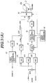
- FIG. 3(A) shows a recording system in a VTR.
- the system includes a video signal processing circuit 10 which will generally include a video signal amplifier, a clamp circuit and the like, for receiving a video signal at a video signal input and providing an output signal to the input of a frequency modulator (FM) 11.
- the output of the frequency modulator 11 is fed to an addition circuit 12A.
- a stereo audio signal having a left channel (LCH) component and a right channel (RCH) component is provided at respective audio inputs for recording.
- An addition circuit 12B is provided to add the left channel and right channel components so as to produce a mixed left and right channel signal (L + R).
- Noise reduction circuits 13A, 13B and 13C are provided for the respective audio signals comprising the left channel component (LCH), the right channel component (RCH), and the mixed left and right channel signal (L + R).
- a left and right channel stereo audio signal frequency modulator (FM) 14 is connected to the output of the mixed channel noise reduction circuit 13C and produces an AFM audio signal which is added to the frequency-modulated (FM) signal in the addition circuit 12A.
- the AFM audio signal is inputted to a switching circuit 18 together with the frequency-modulated video signal and chrominance signal which has been converted to a low frequency band. These signals are superposed, but occupy distinct frequency bands, as shown in Figure 2.
- the AFM audio signal and the FM video signal are then recorded on the video tracks A and B by the rotary heads 2a,2b.
- the inputted audio signals in the left and right channels are also converted into corresponding digital signals by means of an analog-to-digital converter (A/D CON) 15 which is connected to receive the outputs of the noise reduction circuits 13A and 13B. Thereafter, the time axis of the digital signals is compressed by a digital processing circuit 16, in which parity and cyclic redundancy check (CRC) codes are also added. Furthermore, the signal is processed for frequency interleaving to form the PCM audio signal. The PCM audio signal is then provided from the output of the digital processing circuit 16 to a frequency modulator (FM) 17.
- FM frequency modulator
- the PCM audio signal is transmitted from the frequency modulator 17 via the switching circuit 18, which is switched in response to a signal from a timing signal generator 19, to the two rotary heads 2a,2b for recording the PCM audio signal on the auxiliary tracks a,b of the magnetic tape.
- the timing signal generator 19 also controls the operation of the analog-to-digital converter 15 and the digital processing circuit 16.
- the same audio signal (from the same sound source) is converted into an AFM audio signal and a PCM audio signal, one being superposed on the video tracks A and B on which the video signal is also recorded, and the other being recorded on the auxiliary tracks a,b appended to the corresponding video tracks A and B, as shown in Figure 2. It may be noted that the part of the tracks on which the chrominance signal is recorded is omitted from the drawings.
- Figure 3B shows a reproducing system in a VTR according to the preferred embodiment.
- the signals on the video tracks to be outputted from a switching circuit 28 during reproduction or playback are separated into a video signal component and an AFM audio signal component by means of two respective band pass filters 21 and 22.
- the switching circuit 28 is controlled by a timing signal generator 29 during playback.
- the separated video signal may then be outputted through another band pass filter (shown in phantom) if necessary, and via a video signal demodulator 20 to a normal video amplifier (not shown) for receiving the separated video output.
- the separated AFM audio signal is passed to a mixing circuit 30 via a demodulator (DEM) 23 connected to the output of the band pass filter 22 and having its output in circuit with a noise reduction circuit 27B.
- DEM demodulator
- the PCM audio signal recorded on the auxiliary tracks a,b is also retrieved at times specified by the timing circuit 29.
- a digital processing circuit 25 receives the PCM audio signal via a demodulator (DEM) 24 connected to the switching circuit 28, and performs error correction on the basis of the parity and CRC codes, time-axis decompression and deinterleaving.
- the resulting signal is converted into an analog signal by means of a digital-to-analog (D/A) converter 26.
- D/A digital-to-analog
- Both the digital processing circuit 25 and the D/A converter 26 are also controlled during playback by the timing signal generator 29.
- the converted analog signal is sent to the mixing circuit 30 by way of a pair of noise reduction circuits 27A and 27C.
- the mixing circuit 30 includes a switching circuit which selects the demodulated AFM audio signal from the noise reduction circuit 27B, the demodulated PCM audio signal from the noise reduction circuits 27A,27C, or left and right channel signals mixed from both audio signals via addition circuits 31A,31B.
- the mixing circuit 30 further comprises two variable resistors RV11 and RV12 for the left channel (LCH) audio output and two variable resistors RV21 and RV22 for the right channel (RCH) audio output.
- the resistor RV11 controls the AFM signal content mixed by the addition circuit 31A in the right channel, while the resistor RV21 controls the AFM signal mixed in the right channel addition circuit.
- the resistors RV12 and RV22 similarly control the mixing of the demodulated PCM analog signals in the circuits 31A,31B in the left and right channels.
- the audio output can simulate the acoustics of live sound production, as explained below.
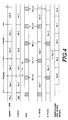
- the two rotary heads record each of the frames of the video signal plus an AFM audio signal Aav1, Bav1, Vietnamese sequentially so that they are recorded alternatingly on tracks An,Bn.
- AFM audio signal Aav1, Bav1, Across Such a sequence is shown in the row labeled VIDEO + AFM, for each of several representative frames.
- Each frame thus comprises an A field and a B field.
- the audio signal Aa1 (shown in the row labeled AUDIO) in the Aav1 field becomes a signal (A)a1 delayed by a period T R with respect to the phase of the audio signal Aa1 in order to allow interleaving, time-axis compression of the audio signal Aa1 and addition of the CRC and parity codes during recording.
- the time compression of the PCM audio signal is shown in the row labeled PCM.
- the PCM audio signal (A)a1 obtained by these means is then recorded on the auxiliary track adjoining the track for the video plus AFM signals in the Aav2 field so as to have a delay of about one field with respect to the Aav1 field.
- Such a recording method is shown in the row labeled A HEAD.
- signals in the B field for each frame are time compressed and recorded, as shown on the chart for the signals Bav1, Ba1, and (B)a1 recorded on the B HEAD track.
- the rotary head 2a continuously reproduces the signal (A)a1 and the video signal plus AFM audio signal Aav2. Since the PCM audio signal derived from the auxiliary track (A)a1 must be time-axis expanded, deinterleaved, and error corrected by the digital processing circuit 25 as shown in Figure 3(B), the PCM audio signal is finally converted into the original analog audio signal Aa1 after a time delay of Tp, as shown in the row labeled REPRODUCED PCM AUDIO SIGNAL. Thus, the PCM audio signal recorded on the auxiliary track is reproduced after a total delay of about one frame and a half (2 1/2 fields) with respect to the AFM audio signal recorded on the video track.
- the resulting sound includes an echo component which provides a surround effect and gives a listener an impression of presence in a concert hall.
- the delay of the PCM audio signal with respect to the AFM audio signal is a natural consequence of the digital processing.
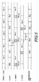
- the audio signal prior to the PCM time compression A a1 may previously start at an intermediate point of one video field and end at an intermediate point in the next field by means of and controlled by the timing signal generator 19.
- the delay with respect to the AFM audio signal reproduced from the video track can be reduced to about two fields.
- the phase difference between the AFM audio signal and the PCM audio signal during reproduction can be adjusted so that the degree of echo effect can be adjusted.
- the helical-scan VTR is provided with a mixing circuit so that an audio output providing an impression of presence similar to that in a concert hall can be achieved.
- This special acoustical effect can also give the impression of a broader sound stage, and hence of a wider video screen.
Landscapes
- Engineering & Computer Science (AREA)
- Chemical & Material Sciences (AREA)
- Nanotechnology (AREA)
- Multimedia (AREA)
- Signal Processing (AREA)
- Health & Medical Sciences (AREA)
- Molecular Biology (AREA)
- General Health & Medical Sciences (AREA)
- Crystallography & Structural Chemistry (AREA)
- Life Sciences & Earth Sciences (AREA)
- Signal Processing For Digital Recording And Reproducing (AREA)
- Recording Or Reproducing By Magnetic Means (AREA)
- Signal Processing Not Specific To The Method Of Recording And Reproducing (AREA)
- Television Signal Processing For Recording (AREA)
Claims (14)
- Gerät zur Wiedergabe von Audiosignalen, die mittels einer drehenden Kopfanordnung (2a, 2b) auf einem Aufzeichnungsmedium (3) aufgezeichnet sind, wobei die Audiosignale ein frequenzmoduliertes Audiosignal (AFM) , das auf Hauptspuren (A, B) aufgezeichnet ist, und ein puls-code-moduliertes Audiosignal (PCM) aufweisen, das auf anschließenden Hilfsspuren (a, b) des Aufzeichnungsmediums aufgezeichnet ist, wobei das frequenzmodulierte (AFM) und das puls-code-modulierte (PCM) Audiosignal von derselben Quelle aufgezeichnet ist, wobei das Gerät aufweist:
- eine Wiedergabeeinrichtung (22 bis 30), um das frequenzmodulierte (AFM) und das puls-code-modulierte (PCM) Audiosignal von den Haupt (A, B)- und den Hilfsspuren (a, b) wiederzugeben, so daß eines gegenüber dem anderen verzögert wiedergegeben ist,
dadurch gekennzeichnet,
daß die Wiedergabeeinrichtung (22 bis 30) eine Einrichtung (30) zum Mischen der wiedergegebenen frequenzmodulierten (AFM) und puls-code-modulierten (PCM) Audiosignale aufweist, um ein gemischtes Audiosignal zu erzeugen, das einen Echoeffekt aufweist. - Gerät nach Anspruch 1, bei dem die Hauptspuren Videospuren (A, B) des Aufzeichnungsmediums (3) sind.
- Gerät zum Aufzeichnen und Wiedergeben von Signalen auf einem Aufzeichnungsmedium (3), wobei das Gerät aufweist:
eine drehende Kopfanordnung (2a, 2b), um auf Hauptspuren (A, B) und auf benachbarten Hilfsspuren (a, b) des Aufzeichnungsmediums (3) Signale aufzuzeichnen und wiederzugeben,
eine Aufzeichnungseinrichtung (10 bis 19), um auf den Hauptspuren (A, B) ein frequenzmoduliertes (AFM) und auf den Hilfsspuren ein puls-code-moduliertes (PCM) Audiosignal aufzuzeichnen, wobei das frequenzmodulierte und das puls-code-modulierte Audiosignal von derselben Quelle aufgezeichnet wird, und
eine Wiedergabeeinrichtung (22 bis 30), um das frequenzmodulierte (AFM) und das puls-code-modulierte (PCM) Audiosignal von den Haupt (A,B) - und den Hilfsspuren (a,b) wiederzugeben, so daß das eine gegenüber dem anderen verzögert wiedergegeben wird,
dadurch gekennzeichnet,
daß die Wiedergabeeinrichtung (22 bis 30) eine Einrichtung (30) aufweist, um das wiedergegebenen frequenzmodulierte (AFM) und das puls-code-modulierte (PCM) Audiosignal zu mischen, um ein gemischtes Audiosignal mit einem Echoeffekt zu erzeugen. - Gerät nach Anspruch 3, bei dem die Hauptspuren Videospuren (A, B) des Aufzeichnungsmediums (3) sind.
- Gerät nach Anspruch 4, bei dem
die drehende Kopfanordnung mehrere drehende Magnetköpfe (2a, 2b) aufweist, die auf einer Drehtrommel angeordnet sind und die zum schrägen Abtasten des Magnetbandes (3) betreibbar ist, das gewunden ist und in einem vorgegebenen Winkel über die Drehtrommel läuft, um die Hilfsspur (a, b) und die Videospur (A, B) für jedes Feld auf dem Magnetband (3) zu bilden, und bei dem
die Aufzeichnungseinrichtung (10 bis 19) betrieben wird, um das puls-code-modulierte (PCM) Audiosignal auf der Hilfsspur (a, b) in zeitachsenkomprimierter Form aufzuzeichnen, und um das frequenzmodulierte Audiosignal (AFM) mit einem Videosignal auf der nachfolgenden Videospur (A, B) mittels der drehenden Köpfe (2a, 2b) für jedes Feld aufzuzeichnen. - Gerät nach Anspruch 5, bei dem die Aufzeichnungseinrichtung eine Einrichtung (16,19) aufweist, um für das auf der Hilfsspur (a,b) aufzuzeichnende Audiosignal bezüglich dem auf der Videospur (A, B) aufzuzeichnenden Audiosignal eine vorgegebene Phasenverzögerung vorzusehen, so daß eine Phasendifferenz zwischen dem auf jeder Videospur (A, B) aufzuzeichnenden Audiosignal und dem auftritt, das von jeder Hilfsspur (a, b) wiedergegeben wird.
- Gerät nach Anspruch 6, bei dem die Phasendifferenz zwischen dem auf jeder Videospur (A, B) aufzuzeichnenden Audiosignal und dem Audiosignal, das von jeder Hilfsspur (a, b) wiedergegeben wird, etwa 2 1/2 Feldern entspricht, wenn die Audiosignale, die auf jeder Videospur und auf jeder Hilfsspur aufzuzeichnen sind, miteinander in Phase sind.
- Gerät nach Anspruch 7, bei dem die Einrichtung (16, 19) zum Vorsehen einer vorgegebenen Phasenverschiebung betrieben wird, um die Audiosignale zum Vorsehen einer einstellbaren Phasenverzögerung zu verarbeiten.
- Gerät nach Anspruch 8, bei dem die vorgegebene Verzögerung im Wesentlichen einem halben Feld enspricht.
- Gerät nach Anspruch 2 oder einem der Ansprüche 4 bis 9, bei dem die Wiedergabeeinrichtung eine Einrichtung (20, 21) aufweist, um, getrennt von den frequenzmodulierten Audiosignalen (AFM) , Videosignale wiederzugewinnen, die mit den frequenzmodulierten Audiosignalen (AFM) auf den Videospuren (A, B) aufgezeichnet sind.
- Gerät nach einem der vorhergehenden Ansprüche, mit einer ersten Signalwiedergewinnungseinrichtung (28, 22, 23), um das frequenzmodulierte Audiosignal (AFM) von der Hauptspur (A, B) wiederzugewinnen und zu verarbeiten und mit einer zweiten Signalwiedergewinnungseinrichtung (28, 24, 25, 26), um die puls-code-modulierten Audiosignale (PCM) von der Hilfsspur (a, b) wiederzugewinnen.
- Gerät nach Anspruch 11, bei dem die Mischeinrichtung (30) eine Einrichtung (RV11, RV12, RV21, RV22) aufweist, um die jeweiligen Amplituden der frequenzmodulierten (AFM) und puls-code-modulierten (PCM) Audiosignale so zu steuern, daß das eine ein Echo des Anderen simuliert.
- Gerät nach Anspruch 11 oder 12, bei dem die Mischeinrichtung (30) betrieben wird, um das frequenzmodulierte (AFM) und das puls-code-modulierte (PCM) Audiosignal mit veränderbarem Phasenoffset zu verbinden.
- Gerät nach einem der vorhergehenden Ansprüche, bei dem die Mischeinrichtung (30) betrieben wird, um ein wiedergegebenes Audiosignal aus dem wiedergegebenen frequenzmodulierten Audiosiugnal (AFM), dem wiedergegebenen puls-code-modulierten Audiosignal (PCM) und dem gemischten Audiosignal, das den Echoeffekt aufweist, auszuwählen und auszugeben.
Applications Claiming Priority (2)
| Application Number | Priority Date | Filing Date | Title |
|---|---|---|---|
| JP60155946A JPH0666942B2 (ja) | 1985-07-17 | 1985-07-17 | ヘリカルスキヤン方式磁気記録再生装置 |
| JP155946/85 | 1985-07-17 |
Publications (3)
| Publication Number | Publication Date |
|---|---|
| EP0209380A2 EP0209380A2 (de) | 1987-01-21 |
| EP0209380A3 EP0209380A3 (en) | 1988-11-23 |
| EP0209380B1 true EP0209380B1 (de) | 1995-09-13 |
Family
ID=15616978
Family Applications (1)
| Application Number | Title | Priority Date | Filing Date |
|---|---|---|---|
| EP86305485A Expired - Lifetime EP0209380B1 (de) | 1985-07-17 | 1986-07-16 | Aufzeichnungs- und/oder Wiedergabevorrichtung |
Country Status (7)
| Country | Link |
|---|---|
| US (1) | US5191487A (de) |
| EP (1) | EP0209380B1 (de) |
| JP (1) | JPH0666942B2 (de) |
| KR (1) | KR940011596B1 (de) |
| AU (1) | AU591149B2 (de) |
| CA (1) | CA1308190C (de) |
| DE (1) | DE3650392T2 (de) |
Families Citing this family (5)
| Publication number | Priority date | Publication date | Assignee | Title |
|---|---|---|---|---|
| JP2580117B2 (ja) * | 1985-12-18 | 1997-02-12 | ソニー株式会社 | 再生装置における音場拡大装置 |
| US5218454A (en) * | 1989-03-28 | 1993-06-08 | Canon Kabushiki Kaisha | Apparatus for improved recording of signals having video and audio components |
| JPH0589594A (ja) * | 1991-09-30 | 1993-04-09 | Sony Corp | ビデオデイスク再生装置 |
| JPH05101533A (ja) * | 1991-10-04 | 1993-04-23 | Sony Corp | Vtr |
| CN106328154B (zh) * | 2015-06-30 | 2019-09-17 | 芋头科技(杭州)有限公司 | 一种前端音频处理系统 |
Family Cites Families (13)
| Publication number | Priority date | Publication date | Assignee | Title |
|---|---|---|---|---|
| US4164884A (en) * | 1975-06-24 | 1979-08-21 | Roland Corporation | Device for producing a chorus effect |
| NL7714502A (nl) * | 1977-12-29 | 1979-07-03 | Philips Nv | Kunstmatige nagalminrichting voor audiofrequen- te trillingen. |
| US4232190A (en) * | 1978-02-06 | 1980-11-04 | Laiacona Michael N | Apparatus for combining phonograph signal with auxiliary audio signal |
| US4237343A (en) | 1978-02-09 | 1980-12-02 | Kurtin Stephen L | Digital delay/ambience processor |
| JPS5523687A (en) | 1978-08-09 | 1980-02-20 | Matsushita Electric Ind Co Ltd | Audio equipment for vehicle use |
| JPS5811159B2 (ja) * | 1979-05-18 | 1983-03-01 | 松下電器産業株式会社 | 車載用音響再生装置 |
| EP0036337B1 (de) | 1980-03-19 | 1985-02-20 | Matsushita Electric Industrial Co., Ltd. | Schallwiedergabesystem mit das Schallbild lokalisierenden Schaltungen |
| WO1981002957A1 (en) | 1980-04-11 | 1981-10-15 | R Lawson | Audio echo circuits |
| JPS5741084A (en) * | 1980-08-25 | 1982-03-06 | Hitachi Ltd | Voice signal recording and reproducing device |
| JPS58222402A (ja) * | 1982-02-02 | 1983-12-24 | Sony Corp | 情報信号の記録装置 |
| DE3382105D1 (de) | 1982-09-10 | 1991-02-14 | Hitachi Ltd | Aufzeichnungs- und wiedergabeanordnung fuer ein videobandaufzeichnungsgeraet. |
| JPS6068793A (ja) * | 1983-09-26 | 1985-04-19 | Sony Corp | カラ−ビデオ信号のデイジタル化回路 |
| NL8303945A (nl) * | 1983-11-17 | 1985-06-17 | Philips Nv | Inrichting voor het realiseren van een pseudo-stereo signaal. |
-
1985
- 1985-07-17 JP JP60155946A patent/JPH0666942B2/ja not_active Expired - Lifetime
-
1986
- 1986-07-15 CA CA000513857A patent/CA1308190C/en not_active Expired - Lifetime
- 1986-07-16 EP EP86305485A patent/EP0209380B1/de not_active Expired - Lifetime
- 1986-07-16 DE DE3650392T patent/DE3650392T2/de not_active Expired - Fee Related
- 1986-07-16 KR KR1019860005751A patent/KR940011596B1/ko not_active Expired - Lifetime
- 1986-07-17 AU AU60269/86A patent/AU591149B2/en not_active Expired
-
1990
- 1990-10-01 US US07/593,270 patent/US5191487A/en not_active Expired - Lifetime
Also Published As
| Publication number | Publication date |
|---|---|
| DE3650392D1 (de) | 1995-10-19 |
| AU6026986A (en) | 1987-01-22 |
| KR940011596B1 (ko) | 1994-12-22 |
| CA1308190C (en) | 1992-09-29 |
| EP0209380A3 (en) | 1988-11-23 |
| AU591149B2 (en) | 1989-11-30 |
| JPS6218185A (ja) | 1987-01-27 |
| EP0209380A2 (de) | 1987-01-21 |
| DE3650392T2 (de) | 1996-02-29 |
| JPH0666942B2 (ja) | 1994-08-24 |
| US5191487A (en) | 1993-03-02 |
| KR870001740A (ko) | 1987-03-17 |
Similar Documents
| Publication | Publication Date | Title |
|---|---|---|
| EP0090582B1 (de) | Gerät zum Aufnehmen/Wiedergeben | |
| JP3508138B2 (ja) | 信号処理装置 | |
| EP0255111A2 (de) | Anordnung zur Aufzeichnung und Wiedergabe von digitalen Signalen | |
| JPH07107759B2 (ja) | 回転ヘッドpcmレコ−ダ | |
| EP0228851B1 (de) | Systeme zur Schallfeldexpansion | |
| EP0318038B1 (de) | Schaltung zur Trennung von gleichzeitig wiedergegebenen PCM- und ATF-Signalen mit mindestens sich partiel überlappenden Frequenzbändern | |
| EP0209380B1 (de) | Aufzeichnungs- und/oder Wiedergabevorrichtung | |
| EP0470815B1 (de) | Verfahren und Gerät zur Aufzeichnung von Video- und Informationssignalen | |
| EP0306964B1 (de) | Aufzeichnungsgerät | |
| EP0370670A2 (de) | Aufzeichnungsgerät des Drehkopftyps | |
| JPH0465473B2 (de) | ||
| JPH04123677A (ja) | Vtrの音声信号記録方法 | |
| US5499104A (en) | Apparatus for recording a video signal and stereophonic audio signals | |
| EP0169910B1 (de) | Magnetisches videoaufzeichnungsgerät mit rotierenden köpfen | |
| JPS5821325B2 (ja) | ドロツプアウトホシヨウソウチオソナエタ タチヤンネルサイセイソウチ | |
| JPS60111369A (ja) | 記録再生装置 | |
| JP2539001B2 (ja) | デイジタル信号記録方法ならびに記録再生装置 | |
| EP0621731A2 (de) | Gerät zur Aufzeichnung und Wiedergabe von digitalen Daten | |
| JP3046109B2 (ja) | 映像信号記録再生装置 | |
| JPH0377564B2 (de) | ||
| JPH0442750B2 (de) | ||
| JPS60258705A (ja) | 情報記録再生装置 | |
| JPH0724090B2 (ja) | 磁気記録再生装置 | |
| JPH05122653A (ja) | カラー映像信号および音声信号の磁気記録再生装置 | |
| JPS63200363A (ja) | 磁気記録再生装置 |
Legal Events
| Date | Code | Title | Description |
|---|---|---|---|
| PUAI | Public reference made under article 153(3) epc to a published international application that has entered the european phase |
Free format text: ORIGINAL CODE: 0009012 |
|
| AK | Designated contracting states |
Kind code of ref document: A2 Designated state(s): DE FR GB NL |
|
| PUAL | Search report despatched |
Free format text: ORIGINAL CODE: 0009013 |
|
| AK | Designated contracting states |
Kind code of ref document: A3 Designated state(s): DE FR GB NL |
|
| 17P | Request for examination filed |
Effective date: 19890331 |
|
| 17Q | First examination report despatched |
Effective date: 19910215 |
|
| GRAA | (expected) grant |
Free format text: ORIGINAL CODE: 0009210 |
|
| AK | Designated contracting states |
Kind code of ref document: B1 Designated state(s): DE FR GB NL |
|
| REF | Corresponds to: |
Ref document number: 3650392 Country of ref document: DE Date of ref document: 19951019 |
|
| ET | Fr: translation filed | ||
| PLBE | No opposition filed within time limit |
Free format text: ORIGINAL CODE: 0009261 |
|
| STAA | Information on the status of an ep patent application or granted ep patent |
Free format text: STATUS: NO OPPOSITION FILED WITHIN TIME LIMIT |
|
| 26N | No opposition filed | ||
| PGFP | Annual fee paid to national office [announced via postgrant information from national office to epo] |
Ref country code: DE Payment date: 20010709 Year of fee payment: 16 |
|
| PGFP | Annual fee paid to national office [announced via postgrant information from national office to epo] |
Ref country code: GB Payment date: 20010711 Year of fee payment: 16 |
|
| PGFP | Annual fee paid to national office [announced via postgrant information from national office to epo] |
Ref country code: FR Payment date: 20010712 Year of fee payment: 16 |
|
| PGFP | Annual fee paid to national office [announced via postgrant information from national office to epo] |
Ref country code: NL Payment date: 20010730 Year of fee payment: 16 |
|
| REG | Reference to a national code |
Ref country code: GB Ref legal event code: IF02 |
|
| PG25 | Lapsed in a contracting state [announced via postgrant information from national office to epo] |
Ref country code: GB Free format text: LAPSE BECAUSE OF NON-PAYMENT OF DUE FEES Effective date: 20020716 |
|
| PG25 | Lapsed in a contracting state [announced via postgrant information from national office to epo] |
Ref country code: NL Free format text: LAPSE BECAUSE OF NON-PAYMENT OF DUE FEES Effective date: 20030201 Ref country code: DE Free format text: LAPSE BECAUSE OF NON-PAYMENT OF DUE FEES Effective date: 20030201 |
|
| GBPC | Gb: european patent ceased through non-payment of renewal fee |
Effective date: 20020716 |
|
| PG25 | Lapsed in a contracting state [announced via postgrant information from national office to epo] |
Ref country code: FR Free format text: LAPSE BECAUSE OF NON-PAYMENT OF DUE FEES Effective date: 20030331 |
|
| NLV4 | Nl: lapsed or anulled due to non-payment of the annual fee |
Effective date: 20030201 |
|
| REG | Reference to a national code |
Ref country code: FR Ref legal event code: ST |
|
| APAH | Appeal reference modified |
Free format text: ORIGINAL CODE: EPIDOSCREFNO |