EP0209495A2 - Fluidumdruckwandler für explosionsgefährdete Atmosphäre - Google Patents
Fluidumdruckwandler für explosionsgefährdete Atmosphäre Download PDFInfo
- Publication number
- EP0209495A2 EP0209495A2 EP86830097A EP86830097A EP0209495A2 EP 0209495 A2 EP0209495 A2 EP 0209495A2 EP 86830097 A EP86830097 A EP 86830097A EP 86830097 A EP86830097 A EP 86830097A EP 0209495 A2 EP0209495 A2 EP 0209495A2
- Authority
- EP
- European Patent Office
- Prior art keywords
- measuring
- cylinder
- pressure transmitter
- diaphragm
- grooves
- Prior art date
- Legal status (The legal status is an assumption and is not a legal conclusion. Google has not performed a legal analysis and makes no representation as to the accuracy of the status listed.)
- Withdrawn
Links
- 239000012530 fluid Substances 0.000 title claims abstract description 18
- 239000002360 explosive Substances 0.000 title claims abstract description 6
- 230000002093 peripheral effect Effects 0.000 claims abstract description 5
- 230000002463 transducing effect Effects 0.000 claims abstract description 4
- 230000001939 inductive effect Effects 0.000 claims abstract description 3
- 230000000875 corresponding effect Effects 0.000 claims abstract 2
- 238000007789 sealing Methods 0.000 claims description 11
- 238000000034 method Methods 0.000 claims description 7
- 230000004323 axial length Effects 0.000 claims description 2
- 238000010276 construction Methods 0.000 abstract description 5
- 208000036366 Sensation of pressure Diseases 0.000 abstract 1
- 238000004880 explosion Methods 0.000 abstract 1
- 239000004020 conductor Substances 0.000 description 2
- 230000003068 static effect Effects 0.000 description 2
- 229910052729 chemical element Inorganic materials 0.000 description 1
- 239000013256 coordination polymer Substances 0.000 description 1
- 238000006073 displacement reaction Methods 0.000 description 1
- 230000000694 effects Effects 0.000 description 1
- 239000007788 liquid Substances 0.000 description 1
- 238000004519 manufacturing process Methods 0.000 description 1
- 239000000463 material Substances 0.000 description 1
- 239000012528 membrane Substances 0.000 description 1
- 239000002184 metal Substances 0.000 description 1
- 239000007769 metal material Substances 0.000 description 1
- 230000035699 permeability Effects 0.000 description 1
- 229920002545 silicone oil Polymers 0.000 description 1
- 238000003466 welding Methods 0.000 description 1
Images

Classifications
-
- G—PHYSICS
- G01—MEASURING; TESTING
- G01L—MEASURING FORCE, STRESS, TORQUE, WORK, MECHANICAL POWER, MECHANICAL EFFICIENCY, OR FLUID PRESSURE
- G01L19/00—Details of, or accessories for, apparatus for measuring steady or quasi-steady pressure of a fluent medium insofar as such details or accessories are not special to particular types of pressure gauges
- G01L19/06—Means for preventing overload or deleterious influence of the measured medium on the measuring device or vice versa
- G01L19/0663—Flame protection; Flame barriers
-
- G—PHYSICS
- G01—MEASURING; TESTING
- G01L—MEASURING FORCE, STRESS, TORQUE, WORK, MECHANICAL POWER, MECHANICAL EFFICIENCY, OR FLUID PRESSURE
- G01L13/00—Devices or apparatus for measuring differences of two or more fluid pressure values
- G01L13/02—Devices or apparatus for measuring differences of two or more fluid pressure values using elastically-deformable members or pistons as sensing elements
- G01L13/025—Devices or apparatus for measuring differences of two or more fluid pressure values using elastically-deformable members or pistons as sensing elements using diaphragms
- G01L13/026—Devices or apparatus for measuring differences of two or more fluid pressure values using elastically-deformable members or pistons as sensing elements using diaphragms involving double diaphragm
Definitions
- This invention relates to a fluid pressure transmitting apparatus suitable for use in potentially explosive atmospheres.
- These transmitters as utilized for sensing differential, relative or absolute pressures, consist, in a manner known per se, of a measuring transducer provided with inductive, capacitive or resistive sensor means, and having at least one measuring chamber including electrical or electronic transducing elements located therein and defined on one side by a measuring diaphragm. On its other side, the measuring chamber is closed by a so-called sealing diaphragm which is in turn connected with the environment (the process) of which it is desired to sense the pressure with reference to vacuum (absolute pressure), to atmosphere (relative or gauge pressure) or to another pressure (differential pressure).
- the measuring chamber is filled with a fluid, in general an oil through which the pressure stresses applied to the sealing diaphragm are transmitted to the measuring diaphragm.
- a fluid in general an oil through which the pressure stresses applied to the sealing diaphragm are transmitted to the measuring diaphragm.
- the sealing diaphragm is omitted and the process atmosphere comes into contact directly with the measuring diaphragm.
- the object of this invention is to provide a fluid pressure transmitter for use in potentially explosive atmosphere, in which the flameproof joint, in addition to comply with the specific safety regulations, is designed so as to be particularly simple and inexpensive in construction and very effective in operation, and, furthermore, to permit the passage area for the flow of fluid to and from the measuring membrane, to be adjusted at will at least to a given extent.
- the above objects are attained in a transmitter of the type as defined herein before, in that the flameproof joint or joints comprise one or more peripheral grooves provided at the interface that is defined by a small cylinder when force-fitted in a corresponding recess.
- the grooves can be provided in an easy manner with each of them complying with the regulations referred to above, while by varying in extent and number said grooves it is possible to provide a desired area of passage for the measuring fluid.
- the small cylinder is force-fitted in the corresponding recess makes for a simple construction and enables for other components of the concerned instrument.
- a transducer comprising a central block C formed by two specularly arranged half-bodies A-B which are tightly joined together as, for example, by welding.
- the block C is fixed and clamped by means of a sleeve member 10 bearing at 12 on block C.
- the two rigid half bodies A and B when coupled and welded together, are holding a measuring diaphragm M in a manner to be locked and sealed in between along its periphery, said measuring diaphragm M defining two so-called measuring chambers HA and HB.
- the measuring diaphragm M has a central block N on which are supported disks 1A and 1B of a material having a high magnetic permeability.
- Each half-body A-B carries a magnetic core 14 and an associated field coil 15, the cores being arranged to face the magnetic disks 1A and 1B on the block N carried by the diaphragm M.
- the coils 15 are supplied with alternating current via leads-in 16 to provide a magnetic field whose lines of force are closed across the magnetic core 14 and the associated magnetic disk 1A, 1B on block N. This will results in obtaining two magnetic circuit which, when the measuring diaphragm M has come to a complete standstill and defines two identical chambers HA and HB, will show the same electromagnetic values.
- Each chamber HA and HB is provided with recesses 17A, 18A and 17B, 18B respectively, in which recesses are located the electrical components and conductors as well as the sealing systems for sealing a filling liquid, as for example silicone oil, subsequent to its admission to the chambers.
- a filling liquid as for example silicone oil
- Each half-body A-B includes a flameproof device 30A-30B to be described hereinafter, with an interspace 20A and 20B bounded externally by a welded and sealed sealing diaphragm 21A, 21B which divides the measuring transducer of the instrument from the process fluid in process chambers CP.
- the differential pressure applied to the two sealing diaphragms 21A and 21B is transferred through said two sealing diaphragm and the filling fluid to the measuring diaphragm M which converts said difference into a small displacement of its block N.
- This will in turn alter the air gaps A and TB between the two disks 1A and 1B and the opposite fixed magnetic circuit formed by the magnetic cores 14 and their AC-supplied coils 15.
- the difference between the final and initial values of the two inductances represents the output from the differential pressure sensing transducer.
- resistors RA and RB are located in the recesses 17A and 17B respectively, which resistors RA and RB are preferably of the carbon-paste type, are sensitive to the static pressure to which the instrument is subjected and are connected via conductors 22 with the processing circuit of the transducer.
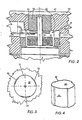
- the flameproof device 30A and 30B is best shown in figures 2 to 4. It essentially comprises a cylindrical recess 32 (figures 2 and 3) and a small metall cylinder 34 having an outer diameter equal to the diameter of the cylindrical recess, with the allowance being such as to permit the cylinder to be force-fitted into the receiving recess 32.
- the cylinder 34 which is made of metal material, has one or more grooves 36 formed on its periphery, the width of which grooves is such as to meet the regulations referred to above, while the overall circumferential extent of the grooves 36 may be chosen, consistent with their width, to ensure passage of the fluid from gap 20 to chamber H, and conversely, under optimum condition for the most effective operation of the instrument.
- the device can be very simple and precise in construction and production thereof on an industrial scale can be achieved with no difficulty.
- no complexity in structure or operation of the instrument is involved when using this device but, on the contrary, the small cylinder, once force-fitted in place, can be utilized as a support for other components of the strument as shown, by way of example, for the core 14 and coil 15.
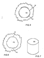
- Figures 5, 6 and 7 show a variation of the flameproof device.
- This device substantially comprises, here again, a cylindrical recess 42 and a small metal cylinder 44 having an outer diameter equal to the diameter of the cylinder recess 42, with the allowance being such that the cylinder 44 can be a tight fit in the cylindrical-receiving recess 42.
- the recess 42 has one or more grooves 46 formed on the inner periphery thereof, the width of which grooves 46 is chosen to meet the regulations referred to above, while as to the overall circumferential extent of the grooves 46 the same considerations are applicable as made in connection with the embodiment in figs. 3 and 4.
- the axial length of the cylinder should be of at least 6mm, the radial size or width of the grooves of the order of 0.08 to 0.15mm, while, as already said, the circumferential extent of these grooves may be varied according to operational requirements for the concerned instrument.
Landscapes
- Physics & Mathematics (AREA)
- General Physics & Mathematics (AREA)
- Measuring Fluid Pressure (AREA)
Applications Claiming Priority (2)
| Application Number | Priority Date | Filing Date | Title |
|---|---|---|---|
| IT21496/85A IT1185212B (it) | 1985-07-09 | 1985-07-09 | Trasmettitore di pressioni di fluidi per atmosfere potenzialmente esplosive |
| IT2149685 | 1985-07-09 |
Publications (2)
| Publication Number | Publication Date |
|---|---|
| EP0209495A2 true EP0209495A2 (de) | 1987-01-21 |
| EP0209495A3 EP0209495A3 (de) | 1989-04-26 |
Family
ID=11182682
Family Applications (1)
| Application Number | Title | Priority Date | Filing Date |
|---|---|---|---|
| EP86830097A Withdrawn EP0209495A3 (de) | 1985-07-09 | 1986-04-29 | Fluidumdruckwandler für explosionsgefährdete Atmosphäre |
Country Status (5)
| Country | Link |
|---|---|
| US (1) | US4733563A (de) |
| EP (1) | EP0209495A3 (de) |
| JP (1) | JPS6285834A (de) |
| ES (1) | ES8701382A1 (de) |
| IT (1) | IT1185212B (de) |
Cited By (6)
| Publication number | Priority date | Publication date | Assignee | Title |
|---|---|---|---|---|
| DE4104811A1 (de) * | 1991-02-16 | 1992-08-20 | Eckardt Ag | Differenzdruckmesszelle |
| EP0493397A4 (en) * | 1989-09-20 | 1992-09-16 | Rosemount Inc. | Pressure transmitter with flame isolating plug |
| US5287746A (en) * | 1992-04-14 | 1994-02-22 | Rosemount Inc. | Modular transmitter with flame arresting header |
| WO1996006338A3 (en) * | 1994-08-22 | 1996-04-11 | Foxboro Co | Differential pressure transmitter |
| DE10314920A1 (de) * | 2003-04-01 | 2004-10-14 | Endress + Hauser Gmbh + Co. Kg | Druckaufnehmer mit Flammendurchschlagsperre |
| US8714019B2 (en) | 2011-04-13 | 2014-05-06 | Vega Greishaber Kg | Measuring cell with a casing for housing a sensor, in particular a pressure transducer |
Families Citing this family (4)
| Publication number | Priority date | Publication date | Assignee | Title |
|---|---|---|---|---|
| DE102007000143B4 (de) | 2007-03-09 | 2010-07-15 | Wika Alexander Wiegand Gmbh & Co. Kg | Acetylen-Manometer mit Schutzdrossel |
| FR2926883B1 (fr) * | 2008-01-24 | 2010-02-26 | Tokheim Holding Bv | Dispositif capteur de pression adapte a des atmospheres explosives ou corrosives |
| US7681456B2 (en) * | 2008-06-20 | 2010-03-23 | Rosemount Inc. | Field device including a capillary tube having a non-cylindrical lumen |
| US8485040B2 (en) | 2011-03-14 | 2013-07-16 | Rosemount Inc. | Flame arrestor for process transmitter |
Family Cites Families (4)
| Publication number | Priority date | Publication date | Assignee | Title |
|---|---|---|---|---|
| US2789192A (en) * | 1950-07-15 | 1957-04-16 | Statham Lab Inc | Vibrometers |
| US3343420A (en) * | 1963-11-29 | 1967-09-26 | Hitachi Ltd | Differential pressure transmitters |
| IT1164315B (it) * | 1983-07-08 | 1987-04-08 | Kent Tieghi Spa | Trasmettitore di pressioni differenziali di fluidi di processo industriali, con compensazione degli effetti delle variazioni di pressione statica |
| FR2555743B1 (fr) * | 1983-11-25 | 1986-04-11 | Sereg Soc | Capteur inductif de pression differentielle |
-
1985
- 1985-07-09 IT IT21496/85A patent/IT1185212B/it active
-
1986
- 1986-04-11 ES ES553907A patent/ES8701382A1/es not_active Expired
- 1986-04-29 EP EP86830097A patent/EP0209495A3/de not_active Withdrawn
- 1986-05-07 US US06/860,486 patent/US4733563A/en not_active Expired - Fee Related
- 1986-07-08 JP JP61158884A patent/JPS6285834A/ja active Pending
Cited By (10)
| Publication number | Priority date | Publication date | Assignee | Title |
|---|---|---|---|---|
| EP0493397A4 (en) * | 1989-09-20 | 1992-09-16 | Rosemount Inc. | Pressure transmitter with flame isolating plug |
| DE4104811A1 (de) * | 1991-02-16 | 1992-08-20 | Eckardt Ag | Differenzdruckmesszelle |
| US5287746A (en) * | 1992-04-14 | 1994-02-22 | Rosemount Inc. | Modular transmitter with flame arresting header |
| WO1996006338A3 (en) * | 1994-08-22 | 1996-04-11 | Foxboro Co | Differential pressure transmitter |
| US5583294A (en) * | 1994-08-22 | 1996-12-10 | The Foxboro Company | Differential pressure transmitter having an integral flame arresting body and overrange diaphragm |
| RU2143673C1 (ru) * | 1994-08-22 | 1999-12-27 | Зе Фоксборо Кампэни | Датчик давления (варианты) |
| US6038927A (en) * | 1994-08-22 | 2000-03-21 | The Foxboro Company | Vertically mounted differential pressure transmitter having an integrally mounted sensor |
| DE10314920A1 (de) * | 2003-04-01 | 2004-10-14 | Endress + Hauser Gmbh + Co. Kg | Druckaufnehmer mit Flammendurchschlagsperre |
| US8714019B2 (en) | 2011-04-13 | 2014-05-06 | Vega Greishaber Kg | Measuring cell with a casing for housing a sensor, in particular a pressure transducer |
| EP2511685B1 (de) * | 2011-04-13 | 2017-07-12 | VEGA Grieshaber KG | Messzelle mit einem Gehäuse zur Aufnahme eines Sensors, insbesondere eines Druckmessumformers |
Also Published As
| Publication number | Publication date |
|---|---|
| EP0209495A3 (de) | 1989-04-26 |
| IT8521496A0 (it) | 1985-07-09 |
| ES553907A0 (es) | 1986-12-01 |
| US4733563A (en) | 1988-03-29 |
| ES8701382A1 (es) | 1986-12-01 |
| IT1185212B (it) | 1987-11-04 |
| JPS6285834A (ja) | 1987-04-20 |
Similar Documents
| Publication | Publication Date | Title |
|---|---|---|
| US5763787A (en) | Carrier assembly for fluid sensor | |
| US3946615A (en) | Pressure transducer | |
| FI102494B (fi) | Paineensiirrin, jossa on jännityksen eristyssyvennys | |
| US6920795B2 (en) | Adapter for coupling a sensor to a fluid line | |
| US4670733A (en) | Differential pressure transducer | |
| EP0209495A2 (de) | Fluidumdruckwandler für explosionsgefährdete Atmosphäre | |
| US5731522A (en) | Transmitter with isolation assembly for pressure sensor | |
| US4395916A (en) | Arrangement for sealing a reactive element within a fluid pressure transducer | |
| US3623371A (en) | Pressure transducers | |
| US4163395A (en) | Pressure transmitter with simplified pressure sensing head | |
| EP0598287A1 (de) | Coriolisdurchflussmesser | |
| US4086815A (en) | Device for use in sensing pressures | |
| US6041659A (en) | Methods and apparatus for sensing differential and gauge static pressure in a fluid flow line | |
| CA1039529A (en) | Pressure sensors utilizing ferromagnetic fluids | |
| JPS6222090B2 (de) | ||
| US4073191A (en) | Differential pressure transducer | |
| US3162795A (en) | Positioning system employing a transducing device having an integral torque generator | |
| JPH09229802A (ja) | 過負荷保護装置を備えた差圧測定変換装置 | |
| US4034610A (en) | Differential pressure measuring device | |
| US4244229A (en) | Differential pressure transducer | |
| US3494190A (en) | Fluid flow transducer | |
| EP0071581B1 (de) | Elektronischer Umsetzer für Fluiddruckwerte | |
| EP0131551A2 (de) | Differenzdruckwandler für Fluide mit Ausgleich von statischen Druckeffekten | |
| US3374674A (en) | Fluid flowmeter | |
| EP3614116A1 (de) | Drucksensoren und methoden zur herstellung von drucksensoren |
Legal Events
| Date | Code | Title | Description |
|---|---|---|---|
| PUAI | Public reference made under article 153(3) epc to a published international application that has entered the european phase |
Free format text: ORIGINAL CODE: 0009012 |
|
| AK | Designated contracting states |
Kind code of ref document: A2 Designated state(s): AT BE CH DE FR GB LI NL SE |
|
| PUAL | Search report despatched |
Free format text: ORIGINAL CODE: 0009013 |
|
| AK | Designated contracting states |
Kind code of ref document: A3 Designated state(s): AT BE CH DE FR GB LI NL SE |
|
| STAA | Information on the status of an ep patent application or granted ep patent |
Free format text: STATUS: THE APPLICATION IS DEEMED TO BE WITHDRAWN |
|
| 18D | Application deemed to be withdrawn |
Effective date: 19891027 |
|
| RIN1 | Information on inventor provided before grant (corrected) |
Inventor name: NAVA, GIANMARIO Inventor name: TEDESCO, PIETRO |