EP0209646B1 - Bassin avec un dispositif d'aération de l'eau - Google Patents
Bassin avec un dispositif d'aération de l'eau Download PDFInfo
- Publication number
- EP0209646B1 EP0209646B1 EP86105565A EP86105565A EP0209646B1 EP 0209646 B1 EP0209646 B1 EP 0209646B1 EP 86105565 A EP86105565 A EP 86105565A EP 86105565 A EP86105565 A EP 86105565A EP 0209646 B1 EP0209646 B1 EP 0209646B1
- Authority
- EP
- European Patent Office
- Prior art keywords
- water
- nozzle
- air
- watertub
- distributor
- Prior art date
- Legal status (The legal status is an assumption and is not a legal conclusion. Google has not performed a legal analysis and makes no representation as to the accuracy of the status listed.)
- Expired
Links
Images

Classifications
-
- A—HUMAN NECESSITIES
- A61—MEDICAL OR VETERINARY SCIENCE; HYGIENE
- A61H—PHYSICAL THERAPY APPARATUS, e.g. DEVICES FOR LOCATING OR STIMULATING REFLEX POINTS IN THE BODY; ARTIFICIAL RESPIRATION; MASSAGE; BATHING DEVICES FOR SPECIAL THERAPEUTIC OR HYGIENIC PURPOSES OR SPECIFIC PARTS OF THE BODY
- A61H33/00—Bathing devices for special therapeutic or hygienic purposes
- A61H33/60—Components specifically designed for the therapeutic baths of groups A61H33/00
- A61H33/601—Inlet to the bath
- A61H33/6021—Nozzles
- A61H33/6057—Comprising means producing pulsating or intermittent streams
-
- A—HUMAN NECESSITIES
- A61—MEDICAL OR VETERINARY SCIENCE; HYGIENE
- A61H—PHYSICAL THERAPY APPARATUS, e.g. DEVICES FOR LOCATING OR STIMULATING REFLEX POINTS IN THE BODY; ARTIFICIAL RESPIRATION; MASSAGE; BATHING DEVICES FOR SPECIAL THERAPEUTIC OR HYGIENIC PURPOSES OR SPECIFIC PARTS OF THE BODY
- A61H33/00—Bathing devices for special therapeutic or hygienic purposes
- A61H33/02—Bathing devices for use with gas-containing liquid, or liquid in which gas is led or generated, e.g. carbon dioxide baths
- A61H33/026—Gas nozzles specially adapted therefor
-
- A—HUMAN NECESSITIES
- A61—MEDICAL OR VETERINARY SCIENCE; HYGIENE
- A61H—PHYSICAL THERAPY APPARATUS, e.g. DEVICES FOR LOCATING OR STIMULATING REFLEX POINTS IN THE BODY; ARTIFICIAL RESPIRATION; MASSAGE; BATHING DEVICES FOR SPECIAL THERAPEUTIC OR HYGIENIC PURPOSES OR SPECIFIC PARTS OF THE BODY
- A61H33/00—Bathing devices for special therapeutic or hygienic purposes
- A61H33/02—Bathing devices for use with gas-containing liquid, or liquid in which gas is led or generated, e.g. carbon dioxide baths
- A61H33/027—Gas-water mixing nozzles therefor
-
- A—HUMAN NECESSITIES
- A61—MEDICAL OR VETERINARY SCIENCE; HYGIENE
- A61H—PHYSICAL THERAPY APPARATUS, e.g. DEVICES FOR LOCATING OR STIMULATING REFLEX POINTS IN THE BODY; ARTIFICIAL RESPIRATION; MASSAGE; BATHING DEVICES FOR SPECIAL THERAPEUTIC OR HYGIENIC PURPOSES OR SPECIFIC PARTS OF THE BODY
- A61H33/00—Bathing devices for special therapeutic or hygienic purposes
- A61H2033/0008—Arrangement for cleaning the installation before or after use
- A61H2033/0016—Arrangement for cleaning the installation before or after use using cleansing products
-
- A—HUMAN NECESSITIES
- A61—MEDICAL OR VETERINARY SCIENCE; HYGIENE
- A61H—PHYSICAL THERAPY APPARATUS, e.g. DEVICES FOR LOCATING OR STIMULATING REFLEX POINTS IN THE BODY; ARTIFICIAL RESPIRATION; MASSAGE; BATHING DEVICES FOR SPECIAL THERAPEUTIC OR HYGIENIC PURPOSES OR SPECIFIC PARTS OF THE BODY
- A61H33/00—Bathing devices for special therapeutic or hygienic purposes
- A61H33/02—Bathing devices for use with gas-containing liquid, or liquid in which gas is led or generated, e.g. carbon dioxide baths
- A61H2033/022—Bathing devices for use with gas-containing liquid, or liquid in which gas is led or generated, e.g. carbon dioxide baths with control means for regulating the air volume aspirated by a water jet
-
- A—HUMAN NECESSITIES
- A61—MEDICAL OR VETERINARY SCIENCE; HYGIENE
- A61H—PHYSICAL THERAPY APPARATUS, e.g. DEVICES FOR LOCATING OR STIMULATING REFLEX POINTS IN THE BODY; ARTIFICIAL RESPIRATION; MASSAGE; BATHING DEVICES FOR SPECIAL THERAPEUTIC OR HYGIENIC PURPOSES OR SPECIFIC PARTS OF THE BODY
- A61H33/00—Bathing devices for special therapeutic or hygienic purposes
- A61H33/02—Bathing devices for use with gas-containing liquid, or liquid in which gas is led or generated, e.g. carbon dioxide baths
- A61H2033/023—Bathing devices for use with gas-containing liquid, or liquid in which gas is led or generated, e.g. carbon dioxide baths with means in the air supply lines to prevent back-feed of water, e.g. anti-backflow valves, draining devices
-
- A—HUMAN NECESSITIES
- A61—MEDICAL OR VETERINARY SCIENCE; HYGIENE
- A61H—PHYSICAL THERAPY APPARATUS, e.g. DEVICES FOR LOCATING OR STIMULATING REFLEX POINTS IN THE BODY; ARTIFICIAL RESPIRATION; MASSAGE; BATHING DEVICES FOR SPECIAL THERAPEUTIC OR HYGIENIC PURPOSES OR SPECIFIC PARTS OF THE BODY
- A61H33/00—Bathing devices for special therapeutic or hygienic purposes
- A61H33/60—Components specifically designed for the therapeutic baths of groups A61H33/00
- A61H33/601—Inlet to the bath
- A61H33/6021—Nozzles
- A61H33/6063—Specifically adapted for fitting in bathtub walls
Definitions
- the invention relates to a water basin with an air bubble device according to the preamble of the main claim.
- a water basin with these features is known from GB-A-2 114 021.
- Such water basins with an air whirlpool device are used for massage purposes, water basins being understood to mean a hand or foot basin, a bathtub but also a whirlpool or a larger basin.
- the massage effect is achieved by an air and / or water jet, which is introduced into the water in the water basin through appropriate nozzles. In this way, on the one hand, the water in the water basin is moved and animated and, on the other hand, the body parts exposed to this jet are massaged.
- the water basin according to the invention with the characterizing features of the claims has the advantages that the air and / or water flow can be designed such that only air and once only water is blasted into the inner basin, or that a water-air mixture within the supply lines or is generated within the nozzles and this is irradiated into the inner pool.
- the channels and lines serving the purpose of supplying water and / or air are preferably arranged such that they empty themselves after use.
- the design of the water channel with an air supply nozzle has the advantage that air can be supplied to the water channel at almost any point, it only needs to be provided with an air inlet.
- the transition point at which one medium enters the other medium is designed as a nozzle, which works in principle as a water jet pump, and both water and air can serve as the propellant jet.
- the principle of the water jet pump is known and therefore does not need to be dealt with here.
- the Bernoulli as well as the Venturi principle can be used.
- the effects result in each case between an inner nozzle and a jet nozzle which is arranged towards the inside of the water basin and serves to shape the jet.
- the further embodiment of the invention has the advantage that water and / or air is supplied to those nozzles which are arranged in the region of the pool floor.
- the invention enables nozzles that do not go beyond the inner surface of the pool wall, so that the bathers do not disturb nozzle bodies protruding from the wall.
- the channels and pipes in whirlpools equipped with a filter and water treatment system to return the filtered water to the inner pool and to use nozzle combinations in the water return channels, which generate a water-air mixture and this in the area of Blast the pelvic floor into the indoor pool.
- nozzle combinations water-air
- the arrangement of nozzle combinations (water-air) for producing a water-air mixture in or near the pool floor of the pool has the advantage that an additional fan for generating a floor bubble is not required.
- the further embodiment of the invention has the advantage that nozzle constructions can accommodate exchangeable inserts which serve for a multiform radiation. It is possible to choose, in addition to the well-known round, point-like massage jet, jet shaping nozzles that enable a fan-shaped, star-shaped, rotating, radially deflected or multi-jet shape, etc., so that, depending on the desired effect, the desired jet shaping nozzle can be used from the inner pool can.
- the outlet nozzle can be designed with a slot-like outlet for water and / or air to produce a fan-like jet, the outlet preferably being rotatable by 90 °, preferably the jet shape should also be adjustable in direction.
- Such an embodiment has the advantage that the slit-like outlet generates a wide massage jet, which acts like a fan and by rotating the outlet nozzle once in its width and exits once in its narrow side.
- this nozzle construction in a quantity-controllable manner, preferably also to store it in a rotating manner and to guide it in a nozzle carrier which is exchangeable.
- the design of rotating nozzles has the advantage that even larger parts of the body can be exposed to such a continuously moving jet.
- Such nozzle inserts for different jet shaping can of course also be used in water basins of the known type.
- the embodiment of the invention with check valves that are assigned to the water and / or air outlet nozzle and / or the steering jet insert has the advantage that the water and or air outlet opening is only open at the time of massage operation and on other occasions undesirable soap residues and other bath water residues in the feed system cannot penetrate.
- the adjustment option is for individual adjustment.
- a further embodiment of the invention has the advantage that the water / air distribution takes place more intensely, air particles are introduced deeper into the inner pool, the massage jet is therefore softer and more pleasant.
- a particularly preferred embodiment of the invention has the advantage, in particular in the case of air supply, that, instead of a large number of individual nozzles with a vertical outlet, a few individual nozzles with a broad effect can be used, the bubble center achieving a particularly strong massage effect.
- the embodiment of the invention with an addition point for chemicals etc. has the advantage of keeping the water and / or air feeds free from germs.
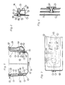
- Fig. 1 shows a water basin in cross section.
- the cavities 3 which serve to guide the water are supplied with water under pressure by a pump (not shown) or by a water supply network via a central line 5, in the former case the pump taking the water from the interior 6 of the water basin or from a surge water tank (not shown) .
- the cavities 3 which serve to guide the water can also consist of several sections, each section being assigned its own inlet connection with at least one jet nozzle for water and / or air. From the cavities 3, the pressurized water is blasted into the inner basin through the nozzle 13, which is arranged below the water level of the inner basin 6, in the basin wall 1.
- the nozzle 13 can be formed by a simple bore in the basin wall 1, it can be developed in many ways, for example as a flange 9, which projects into the channel 3.
- the flange 9 can be fastened both in the basin wall 1 and, for example, by a device inside the channel 3.
- the nozzle 13 can be held by a carrier 14 which, for the purpose of regulating the quantity, enables axial adjustment up to the shut-off, allows a beam deflection in different emission directions, and the interchangeability of different nozzles
- beam shaping round, fan-shaped, rotating, star-shaped, etc.
- the different variants always have the common feature of protruding with the rear end 13 A into at least one channel 3 or 4 or feed line.
- the nozzle 11 carrying the second medium shows the inner nozzle and preferably serves as an air nozzle, into the channel 3 filled with water.
- the nozzle 13 works together with the nozzle 11 in the manner of a water jet pump.
- Fig. 1 two variants of an embodiment are shown side by side.
- the extension of the air supply nozzle 11 is connected via a hose 26 to the supply air valve 27, which is inserted into the upper edge 28 of the water basin.
- the air intake valve 27 can be designed as a regulating valve in order to throttle intake air more or less or to interrupt the air supply.
- a blower can of course also be connected to the feed line 26, which feeds compressed air to the nozzle 11.
- the blower can either be arranged under the water basin floor or can be arranged in the place of the supply air valve 27 on the upper basin edge or in the edge area 33.
- the regulating valve 27 can preferably be designed as a check valve or solenoid valve.
- a variant is shown in the left half of FIG. 1, in which the limiting valve 2 covers a water-carrying cavity 3 and an air-carrying cavity 4. Basically, this variant works like the other.
- a line 32 is indicated below the water basin, which gives an indication of a further variant of the air duct.
- the air supply can also be brought about by an air pressure-generating blower and then introduced from this central point 32 of the air supply nozzle 11 or into the cavity 4, in which further air outlet openings are inserted.
- significantly larger amounts of air can be blown into the water basin than is possible with the water jet pump principle.
- a simple hole in the basin wall 1 can also be used for the air outlet, and a flange with connection of a connecting hose or connecting tube is also conceivable for the air supply.
- air blown in under pressure serves as pump medium and water is entrained, namely according to the Venturi principle, as is used, for example, in liquid atomizers.
- Air can be carried out axially and the water flow coaxially or vice versa.
- the nozzle body 35 preferably clamps the unit 77 to the pool wall 1 via a screw thread.
- the unit 77 carries on the back connecting pieces 5, 32 for the media.
- the unit 77 is connected to the water basin by at least two outlet openings 7, the outlet openings being able to take place in any shape (circular, in a straight direction next to one another or one above the other, also in two rows and in parallel).
- channels 3 and / or 4 formed flat under the pool floor.
- two channels 3 are provided for the water supply and in between the channel 4 for the air supply, the water and / and / or air outlet openings 7 are supplied with air from the duct 4.
- the channel 4 can be ventilated via a line 26 to the tub edge.
- floor nozzles can also be connected individually with pipes and hoses 26 according to FIG. 1 right variant.
- Fig. 4 shows a nozzle combination
- the water is supplied through the channel 3.
- a device 56 is provided which acts as a check valve.
- the check valve opens due to pump pressure and closes automatically.
- the reset can be carried out by the force of a spring or by the backflow of the bathing water, which acts as soon as the pump pressure is switched off.
- the check valve 56 can be designed in such a way that it blocks both the water outlet from channel 3 and the air outlet from channel 4 or at least one of the outlets.
- the media water and / or air can of course be supplied via a pipe or hose line.
- the flow rate can also be regulated by means of the device 56 in that more or less cross-section is released.
- the device 56 also acts as a baffle plate and widens the emerging water jet, which improves the mixing of air and water and reduces air bubbles.
- the device 56 can be held by a carrier flange, the device 56 is preferably attached to a steering beam insert which can be exchanged for the purpose of different beam shaping.
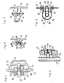
- FIG. 5 shows a carrier flange 9, which is equipped with an internal thread 19, over which an axially adjustable nozzle carrier 14 is guided and through which the nozzle 13 is held in a quantity-adjustable and jet-deflectable manner.
- the nozzle 13 is designed with a spherical surface 23 and is pivotably mounted in the nozzle carrier. By rotating the nozzle carrier 14, the nozzle 13 is moved axially against the air supply nozzle 11, which causes a change in cross section in the annular channel 29.
- the nozzle carrier 14 can be screwed into the carrier flange 9 until the inlet on the back of the nozzle is interrupted.
- this construction it is also possible with this construction to design the shut-off for both water and air using a check valve or a seal.
- a sealing ring which opens at pump pressure and seals between the nozzle 13 and the air supply pipe 11 when the pump pressure is switched off.
- Spring force can be used for resetting.
- the use of a spring-loaded baffle plate 56 (FIGS. 4, 6, 8, 10) with a check valve is also conceivable.
- the tangential water supply on the back of the carrier flange 9 is advantageous.
- the water jet is twisted by tangential water supply.
- This embodiment of a nozzle construction according to the invention also enables the jet shaping device to be replaced.
- FIG. 6 shows a further variant of the nozzle 13 which is used for beam deflection, quantity regulation and beam shaping.
- the nozzle unit is exchangeable, it can be guided in a support flange or inserted directly into the basin wall 1.
- the nozzle 13 is guided via a screw thread in a partial ball.
- a pressure-adjustable nozzle part can of course also be used, which is preferably sealed by an O-ring.
- the free cross section in the annular channel 29 is changed by rotating or shifting the elongated nozzle of the nozzle 13, which also serves as a deflection nozzle, against the air supply nozzle 11.
- FIG. 7 shows a variant of the nozzle 13, which enables a fan-like beam shape, can be mounted rigidly or adjustable in direction and can also be exchanged.
- the water outlet can be made adjustable by axial extension.
- the nozzle 13 it is proposed to equip the nozzle 13 with a slot-like outlet 16, the slot-like outlet being integrally formed on a ball, but it is also conceivable to use both the nozzle in FIG. 6 and the nozzle shown in FIG. 7 instead of a ball-like one
- the disc 17 can be held and pivoted in a hollow spherical bearing.
- the disk 17 preferably carries an O-ring seal on its outer circumference.
- a check valve can also be used with this nozzle construction as described above.
- FIG. 8 shows a distributor and shut-off device 60 according to the invention, which is used in particular for nozzle constructions with an axial water outlet and radial or coaxial air guidance.
- the distributor 60 serves at the same time as a check valve, which preferably saves the water outlet and the air outlet at the same time.
- a compression spring 62 can serve to reset the valve, but the reset can also be effected by the reflux water. Of course, the reset can also be done manually.
- the distributor 60 preferably also serves to regulate the jet and to shut off the outlet nozzle 11 and / or 13.
- the distributor 60 is adjustable against the water outlet 63 by means of a screw thread with adjustment option 65.
- the distributor can be fastened both within the nozzle carrier 9 and on one of the nozzles 11 or 13.
- the distributor 60 is designed according to the invention as a diffuser 61, preferably with a sieve-like device, with a large number of small openings (pores) 61 which produce a large number of venturi effects.
- the distributor 60 with diffuser 61 can be mounted rigidly (without resetting), it can of course also be used in nozzle constructions with axial air and coaxial water flow, and this device according to the invention can also be installed in any type of beam deflection device.
- connection part 57 on the back of the water basin, which is connected to the nozzle carrier 9 and clamps the basin wall 1 like a screw closure.
- the connecting part 57 is formed with at least one connection for the water supply 59.
- the connections 58 and 59 lie one inside the other, they are designed for connecting a pipe-in pipe system.
- the pipe-in pipe connections can be designed on one side as well as on several sides in the manner of a distribution on the connecting part 57.
- the connecting part 57 On the inside, the connecting part 57 carries axially to the nozzle carrier 9 a nozzle 11 through which water or air can be supplied.
- the second medium that is not introduced through the nozzle 11 is introduced radially or coaxially.
- the inner tube 58 can preferably be led out at the rear end of the connecting piece 67 (dashed line).
- the outlet nozzle 11 can be provided with a distributor device 60 with openings 61.
- the nozzle 13 can also carry such a device.
- a check valve can also be installed in this nozzle construction, and steering jet and jet shaping devices of the most varied types can also be used.
- FIG. 10 shows the configuration of a nozzle combination, which is both adjustable in quantity, lockable and also adjustable in direction, preferably carries an independent check valve 56 and / or can also be switched off manually can.
- the exchange of the nozzle insert for different jet shapes is conceivable.
- the extension of the air supply nozzle 11 protrudes into the air-guiding duct 4, a support flange 9 is inserted coaxially with the air supply nozzle in the pool wall 1 and carries an axially adjustable ring 10 with a conical inner bore, which together with the air supply nozzle 11 forms an annular duct 29, the free cross-section can be changed by adjusting the ring 10.
- the adjustment of the ring 10 is preferably carried out from the inner basin, with the steering jet nozzle 22, for example, engaging in bores by means of tapping against pressure against the spring 25. It is not only possible to regulate the quantity but also to shut off the supply of a medium. For this purpose, the ring 10 only needs to be screwed in until it abuts a stop 64.
- the beam is deflected by a steering jet nozzle 22, which preferably has a spherical surface.
- the steering jet nozzle which also serves to shape the jet, is preferably held by a screw ring 12.
- the compression spring 25 preferably serves as the counterbearing for the steering jet nozzle.
- the nozzle construction can additionally have a check valve, preferably according to FIG. 8, which also serves as a baffle plate 56 and closes the nozzle outlet when the pump pressure is switched off Installation of a check valve 56 directly in the steering jet nozzle 22.
- a check valve preferably according to FIG. 8, which also serves as a baffle plate 56 and closes the nozzle outlet when the pump pressure is switched off Installation of a check valve 56 directly in the steering jet nozzle 22.
- the ring 10 in which case the restoring force of a spring 25 can be used or the restoring force of the bath water flowing back.
- the ring 10 only needs to be freely supported when reset. it seals against the stop 64.
- a check valve can of course also be installed in the form of a check ball, a flap or in the form of a lip seal.
- the carrier flange 9 has an internal thread 19 and receives a cylindrical nozzle part 18 with an external thread 19 A, the nozzle part 18 has on the one hand a coaxial bore as a nozzle 13 and on the other hand an eccentric bore 20 which serves for the beam deflection and the beam shaping.
- the nozzle part 18 is exchangeable. However, it is also conceivable to mount the nozzle part 18 in a resilient manner, the supply lines opening automatically when the pump pressure is switched on and closing the supply lines when the pump pressure is switched off.
- the jet deflection and quantity regulation takes place from the inner basin by rotating the nozzle part 18.
- the rotation again causes a change in the flow conditions in the annular channel 29 between the air supply nozzle 11 and the nozzle 13.
- the nozzle part 18 can of course be screwed into the carrier flange 9 until a shut-off of the water inflow is effected.
- a check valve 56 can be installed as described above (FIG. 4). The installation of a different check valve design is also possible.
- FIG. 12 shows a nozzle variant according to the invention, which is used in particular for the irradiation of air, the irradiation taking place largely parallel to the water basin wall or water basin floor surface.
- This construction which is particularly suitable for the pool floor, enables a star-shaped radiation with a large distribution.
- water or a water / air mixture can also be blasted through this nozzle.
- this can also be equipped with details of the nozzles described above, it can be used in a duct system or in a pipe connection system.
- the nozzle holder 9 is inserted, which preferably carries a ball check valve 74.
- a flap check valve is also conceivable.
- At least one outlet opening 69 is provided parallel or approximately parallel to the pool wall 1, through which the respective medium can exit into the pool interior 6.
- at least one axially acting outlet opening 70 can of course also be provided.
- the nozzle holder 9 preferably holds a removable cover 75 which can have rotatable lateral interruptions which serve for the discharge of at least one medium and which can preferably be opened and closed or regulated by a rotary movement.
- the nozzle holder can of course also be connected via hose lines 26, via which the connection to a pressure generator is made.
- the medium outlet openings 69, 70 in a star-shaped arrangement allow the check ball 74 to rotate, which alternately covers the outlet openings while rotating in the housing and thus causes the medium to pulsate.
- a rotor wheel below the cover 75, which, driven by a medium (air or water or a mixture), radially deflects the medium towards the outlet openings and twists it like a screw.
- the medium is pulsed due to lateral interruptions in the outlet.
- FIG. 13 shows a further variant of a nozzle construction according to the invention, which is also suitable for both water, air or mixture radiation. It can be used in a duct system, it can also be connected via pipes or hoses.
- the nozzle holder 9 is clamped in the basin wall 1.
- a lid valve 72 as is known in terms of shape, for example as a plug valve, is mounted in the circumferential outlet opening 71 of the nozzle carrier 9.
- the outlet openings can also be formed from a multiplicity of bores, as is known in terms of shape, for example in gas burners.
- the cover valve 72 In the idle state, the cover valve 72 preferably sits in the seat 73 at approximately the same height as the installation level 1. When the pump pressure is present, the cover valve 72 is lifted out of its seat 73 and the outlet path for the medium is cleared. When the pressure in the medium decreases, the cover valve 72 is returned to its seat by the pressure of the pool water, it preferably serves as a check valve, but a ball check valve 74 may also be present.
- the dead weight can of course also be used for resetting.
- the cover valve 72 is exchangeably mounted in the carrier flange 9, the medium outlet can circulate around the cover valve without interruption, but the medium outlet can also have interruptions, which leads to a radial or star-shaped beam shape.
- the cover valve can also have at least one axially acting medium outlet opening 70. According to the invention and preferably, it is proposed to design the lateral outlet 71 in such a way that lateral bores deflect radially-tangentially and cause the cover valve 72 to rotate.
- a nozzle variant 13 shows an embodiment of a nozzle variant 13 according to the invention, which is formed by a rotor 21 which is mounted on the air supply nozzle 11 and is used for circular jet shaping.
- the carrier flange 9 is designed as a holder, as in the previous variants.
- the rotor 21 is preferably held on the end face by the outlet link (44).
- the outlet gate can have interruptions 45 at the provided locations, which interrupts and pulsates the emerging water and / or air jet. It is also possible to mount the rotor radially or to feed the driving medium axially or radially to the nozzle combination.
- the rotor can be exchanged for another jet shaping device.
- the rotor itself can serve as a check valve and create a seal between the nozzle 13 and the air supply nozzle 11.
- a check valve 56 according to FIG. 4 is also conceivable. also a non-return ball, flap device or lip seal.
- FIG. 14 shows a cross section of an additive addition point 50 according to the invention, which preferably opens into the circulation system 52 starting at the pool edge 51.
- the filling opening 53 is equipped with a sieve-like retaining device 54 and provided with a sealing closure 55.
- the retention device 54 inevitably empties when the water basin contents are emptied, the solution resulting in the sewer or pipe system.
- the addition point can be formed as an independent fitting (standpipe, container).
- a float valve can preferably also be used.
- the use of a solenoid valve is also conceivable, and the emptying can be controlled via the valves.
Landscapes
- Health & Medical Sciences (AREA)
- Public Health (AREA)
- Epidemiology (AREA)
- Pain & Pain Management (AREA)
- Physical Education & Sports Medicine (AREA)
- Rehabilitation Therapy (AREA)
- Life Sciences & Earth Sciences (AREA)
- Animal Behavior & Ethology (AREA)
- General Health & Medical Sciences (AREA)
- Veterinary Medicine (AREA)
- Nozzles (AREA)
- Percussion Or Vibration Massage (AREA)
Claims (14)
Priority Applications (1)
| Application Number | Priority Date | Filing Date | Title |
|---|---|---|---|
| AT86105565T ATE39322T1 (de) | 1985-04-26 | 1986-04-22 | Wasserbecken mit luftsprudelvorrichtung. |
Applications Claiming Priority (4)
| Application Number | Priority Date | Filing Date | Title |
|---|---|---|---|
| DE3515139 | 1985-04-26 | ||
| DE19853515139 DE3515139A1 (de) | 1985-04-26 | 1985-04-26 | Wasserbecken mit luftsprudelvorrichtung |
| DE3607788 | 1986-03-08 | ||
| DE19863607788 DE3607788A1 (de) | 1985-04-26 | 1986-03-08 | Wasserbecken mit luftsprudelvorrichtung |
Publications (4)
| Publication Number | Publication Date |
|---|---|
| EP0209646A2 EP0209646A2 (fr) | 1987-01-28 |
| EP0209646A3 EP0209646A3 (en) | 1987-09-23 |
| EP0209646B1 true EP0209646B1 (fr) | 1988-12-21 |
| EP0209646B2 EP0209646B2 (fr) | 1995-08-16 |
Family
ID=25831747
Family Applications (1)
| Application Number | Title | Priority Date | Filing Date |
|---|---|---|---|
| EP86105565A Expired - Lifetime EP0209646B2 (fr) | 1985-04-26 | 1986-04-22 | Bassin avec un dispositif d'aération de l'eau |
Country Status (2)
| Country | Link |
|---|---|
| EP (1) | EP0209646B2 (fr) |
| DE (4) | DE3607788A1 (fr) |
Cited By (1)
| Publication number | Priority date | Publication date | Assignee | Title |
|---|---|---|---|---|
| EP0445504B1 (fr) * | 1990-02-19 | 1994-11-23 | Ucosan B.V. | Bain tourbillonnant muni d'une tuyère à jet d'eau |
Families Citing this family (32)
| Publication number | Priority date | Publication date | Assignee | Title |
|---|---|---|---|---|
| DE3745124C2 (de) * | 1986-09-10 | 1999-09-02 | Schuessler | Hydromassagedüse |
| DE3744984C2 (de) * | 1986-09-10 | 1995-11-09 | Guenter Schuessler | Hydromassagedüse zur Erzeugung eines Luftsprudels in einem Wasserbecken |
| DE3630806A1 (de) * | 1986-09-10 | 1988-03-17 | Schuessler Guenter | Duesenkombination zur erzeugung eines luftsprudels in einem wasserbecken |
| DE8631764U1 (de) * | 1986-11-27 | 1987-06-25 | Ucosan B.V., Roden | Austrittsdüse für das Austrittsventil einer Whirlpool-Wanne |
| DE3644109A1 (de) * | 1986-12-23 | 1988-07-07 | Hoesch Metall & Kunststoffwerk | Badewanne mit luftsprudelsystem |
| DE3644110A1 (de) * | 1986-12-23 | 1988-07-07 | Hoesch Metall & Kunststoffwerk | Luftduese fuer eine badewanne mit luftsprudelsystem und badewanne aus kunststoff mit einer integrierten duesenanordnung |
| DE3707937C1 (en) * | 1987-03-12 | 1988-03-03 | Kaldewei Franz Gmbh & Co | Nozzle for insertion in a bore in a bathtub |
| DE3720637C1 (en) * | 1987-03-12 | 1988-06-01 | Kaldewei Franz Gmbh & Co | Nozzle for installation in a borehole in a bath tub |
| DE3745024C2 (de) * | 1987-05-06 | 1995-01-19 | Guenter Schuessler | Wasserbecken mit Luftsprudelvorrichtung |
| DE3716683A1 (de) * | 1987-05-19 | 1988-12-01 | Schuessler Guenter | Hydro-massageduese mit angebautem druckerzeuger |
| DE3800401C3 (de) * | 1987-09-16 | 1995-09-07 | Kaldewei Franz Gmbh & Co | Whirlpool-Badewanne |
| IT1222869B (it) * | 1987-10-12 | 1990-09-12 | Jacuzzi Europ | Perfezionata bocchetta per idromassaggio a chiusura automatica |
| IT1231901B (it) * | 1987-10-19 | 1992-01-15 | Jacuzzi Europ | Complesso per disinfezione del circuito idraulico di un impianto di idromassaggio |
| DE3800400C2 (de) * | 1988-01-09 | 1995-02-09 | Kaldewei Franz Gmbh & Co | Whirlpool-Badewanne |
| US4901379A (en) * | 1988-04-25 | 1990-02-20 | Hydrabaths, Inc. | Air excitation hydromassage system |
| GB8818760D0 (en) * | 1988-08-08 | 1988-09-07 | Hahn A B | Portable spa bath |
| IT217548Z2 (it) * | 1988-12-07 | 1991-12-19 | Jacuzzi Europ | Bocchetta di uscita per impianto di idromassaggio |
| EP0376844B1 (fr) * | 1988-12-29 | 1994-08-10 | Toto Ltd. | Construction d'une buse d'évacuation pour faire varier automatiquement le volume d'eau à évacuer |
| DE3902117C1 (fr) * | 1989-01-25 | 1990-09-13 | Guenter 6074 Roedermark De Schuessler | |
| DE3903477A1 (de) * | 1989-02-06 | 1990-08-09 | Viegener Ii Fa Franz | Mischgehaeuse mit drehbar gelagerter einlassduese fuer whirlpool-wannen |
| ATE116537T1 (de) * | 1989-05-03 | 1995-01-15 | Mariani Rubinetterie | Düse für hydromassagewanne. |
| EP0437048A3 (fr) * | 1989-12-12 | 1991-07-24 | Carrier, Roger | Appareil pour l'hydromassage et dispositif à clapet anti-retour pour ledit appareil |
| DE3941819C1 (fr) * | 1989-12-19 | 1991-06-13 | Martin T. 4030 Ratingen De Schydlo | |
| DE4010976C1 (fr) * | 1990-04-05 | 1991-07-25 | Martin T. 4030 Ratingen De Schydlo | |
| DE4109757C2 (de) * | 1991-03-25 | 1993-11-11 | Baasch Elke | Vorrichtung zur Zugabe von Chemikalien in das Umlaufsystem für ein Sprudelbad |
| DE4129217C2 (de) * | 1991-09-03 | 1994-12-08 | Kaldewei Franz Gmbh & Co | Whirlpool-Badewanne mit Einrichtungen zum Erzeugen von Wasser- oder Wasser-/Luftstrahlen |
| US5381563A (en) * | 1992-12-24 | 1995-01-17 | Roger Carrier | Check valve, and hydromassaging apparatus comprising at least one of such a check valve |
| EP0682932B1 (fr) * | 1994-03-21 | 1999-10-27 | Baasch, Elke | Dispositif pour orienter le jet d'une buse d'hydromassage |
| ITTV940061U1 (it) * | 1994-11-23 | 1996-05-23 | Jacuzzi Europ | Dispositivo di variazione ciclica del flusso d'acqua per bocchette di erogazione per idromassaggio. |
| GB0104339D0 (en) * | 2001-02-21 | 2001-04-11 | Airbath Internat Uk Ltd | Baths |
| US20050235409A1 (en) * | 2004-04-23 | 2005-10-27 | Sisk Thomas J | Self draining fitting for a whirlpool bath |
| ES2761257T3 (es) * | 2012-11-05 | 2020-05-19 | Bullfrog Int L C | Bañeras y sistemas de baño con módulos de chorro intercambiables avanzados |
Family Cites Families (33)
| Publication number | Priority date | Publication date | Assignee | Title |
|---|---|---|---|---|
| DE238865C (de) * | 1910-09-24 | 1911-10-05 | Verstellbare Vorrichtung zum Einführen von Gasen in Badewannen u. dgl. | |
| US2856611A (en) * | 1955-07-01 | 1958-10-21 | Velonis Stamatis George | Therapeutic bath device |
| US3099986A (en) * | 1962-06-19 | 1963-08-06 | James V Guelfi | Portable whirlpool device |
| US3251071A (en) * | 1963-07-26 | 1966-05-17 | Probe And Develop Inc | Therapeutic bathtub |
| US3467969A (en) * | 1966-10-27 | 1969-09-23 | Edmond Bordeaux Szekely | Bathing vessel,liquid agitated by multiple jets of air |
| FR1521497A (fr) * | 1967-03-07 | 1968-04-19 | Mediterraneenne D Aerosols Soc | Masseur par pulsations |
| US3421702A (en) * | 1967-08-02 | 1969-01-14 | Spraying Systems Co | Adjustable multiple fluid atomizing nozzle |
| US3483863A (en) * | 1968-01-16 | 1969-12-16 | Harry M De Vane | Therapy pool for use in swimming pools |
| DE2060048A1 (de) * | 1970-12-07 | 1972-06-15 | Berthold & Sutter Abflg Appbau | Vorrichtung zur Durchfuehrung von Wechselbaedern |
| US3948252A (en) * | 1973-07-09 | 1976-04-06 | Montagne Jean Baptiste | Apparatus for hydrotherapeutic treatment |
| US3874374A (en) * | 1974-02-19 | 1975-04-01 | Jacuzzi Research Inc | Hydromassage tub and air induction system therefor |
| DE2417708A1 (de) * | 1974-04-11 | 1975-10-23 | Angelo Rocco D | Unterwassermassagebadewanne |
| DE2432126C3 (de) * | 1974-07-04 | 1981-07-02 | Hans A. Dipl.-Ing. 8400 Regensburg Wichmann | Automatisches Therapiegerät zur Behandlung durch Flüssigkeitsstrahlen |
| US4000528A (en) * | 1975-03-10 | 1977-01-04 | Posnick Irving H | Whirlpool tub and method of making same |
| DE2614459A1 (de) * | 1976-04-03 | 1977-10-06 | Werner Dipl Ing Thomsen | Unterwassermassagegeraet |
| US4149281A (en) * | 1976-09-20 | 1979-04-17 | Industrial Molded Fiberglass | Floating spa |
| US4126905A (en) * | 1977-05-16 | 1978-11-28 | Fox Pool Corporation | Floating therapy pool |
| DE2730867B2 (de) * | 1977-07-08 | 1979-08-09 | Baumann-Beltron Gmbh, Niederhelfenschwil, Sankt Gallen (Schweiz) | Sprudelvorrichtung zur Verwendung in Badewannen |
| US4119686A (en) * | 1977-10-03 | 1978-10-10 | California Cooperage | Hydro-jet fitting for hot tub |
| DE2817187C3 (de) * | 1978-04-20 | 1981-08-06 | Rieber Werke, Heinrich Rieber KG, 7410 Reutlingen | Auswechselbare elektrische Einbau-Heizvorrichtung für ein Gefäß, insbesondere für ein Speisetransportgefäß |
| DE2919313A1 (de) * | 1979-05-14 | 1980-11-27 | Theo Kilian | Badewanne |
| DE2940269C2 (de) * | 1979-10-04 | 1983-10-20 | Horst 6712 Bobenheim Haseloff | Verfahren zur Reinigung des Badewassers bei einer im öffentlichen Bereich einsetzbaren Warmsprudelbeckenanlage (Whirlpool) und hierzu geeignete Vorrichtung |
| US4261347A (en) * | 1979-12-06 | 1981-04-14 | Jacuzzi Bros., Inc. | Hydromassage fitting for tubs, spas and pools |
| AT374678B (de) * | 1980-05-19 | 1984-05-25 | Dupont Robert | Halteventil fuer ausrichtbare einspritzung |
| DE3221647C2 (de) * | 1980-12-11 | 1987-02-26 | Paul Salzburg Haslauer | Vorrichtung zum Verabreichen von Voll- oder Sitzbädern |
| CA1183888A (fr) * | 1980-12-22 | 1985-03-12 | Harvey E. Diamond | Buse de decharge de fluide sous pression sous forme de jet a configuration continuellement variable |
| US4340982A (en) * | 1981-03-24 | 1982-07-27 | Hart James F | Hydrotherapy bath or spa |
| ATE32559T1 (de) * | 1981-10-27 | 1988-03-15 | Cleo Donald Mathis | Duesen zur erzeugung von wasserwirbeln. |
| FR2519272B1 (fr) * | 1982-01-04 | 1986-12-19 | Chalberg Philip | Buse melangeuse reglable d'air et d'eau |
| GB2114021B (en) * | 1982-01-19 | 1985-05-22 | Clive Richard Randle | Baths |
| US4422191A (en) * | 1982-09-29 | 1983-12-27 | Jope Manufacturing Company Inc. | Hydrotherapy jet for tubs, spas or pools |
| FR2556957B3 (fr) * | 1983-12-23 | 1986-04-11 | Delepine Jean C | Systeme de bains pour personnes avec soufflage d'air |
| GB8400995D0 (en) * | 1984-01-14 | 1984-02-15 | James Ind Ltd | Bath installations/tubs |
-
1986
- 1986-03-08 DE DE19863607788 patent/DE3607788A1/de active Granted
- 1986-03-08 DE DE8606463U patent/DE8606463U1/de not_active Expired
- 1986-04-22 EP EP86105565A patent/EP0209646B2/fr not_active Expired - Lifetime
- 1986-04-22 DE DE8686105565T patent/DE3661460D1/de not_active Expired
- 1986-09-08 DE DE8625515U patent/DE8625515U1/de not_active Expired
Cited By (1)
| Publication number | Priority date | Publication date | Assignee | Title |
|---|---|---|---|---|
| EP0445504B1 (fr) * | 1990-02-19 | 1994-11-23 | Ucosan B.V. | Bain tourbillonnant muni d'une tuyère à jet d'eau |
Also Published As
| Publication number | Publication date |
|---|---|
| DE8606463U1 (de) | 1986-10-30 |
| EP0209646A2 (fr) | 1987-01-28 |
| DE3661460D1 (en) | 1989-01-26 |
| DE3607788A1 (de) | 1986-12-04 |
| EP0209646A3 (en) | 1987-09-23 |
| EP0209646B2 (fr) | 1995-08-16 |
| DE8625515U1 (de) | 1986-12-18 |
Similar Documents
| Publication | Publication Date | Title |
|---|---|---|
| EP0209646A2 (fr) | Bassin avec un dispositif d'aération de l'eau | |
| DE69406928T2 (de) | Badevorrichtung mit wasserrückführung | |
| EP0290476B2 (fr) | Buse d'hydromassage generatrice de bouillonnements dans un bassin d'eau | |
| DE2205612A1 (de) | Vorrichtung und Anlage zum Behandeln von Flüssigkeiten, insbesondere Trinkwasser oder Abwasser | |
| WO1996008614A1 (fr) | Pomme de douche permettant l'adjonction de differents ingredients et d'air | |
| EP0590228B2 (fr) | Bassin d'eau avec dispositif à jets d'air | |
| DE2646742A1 (de) | Vorrichtung fuer die erzeugung von blaeschen in einer fluessigkeit | |
| WO2009109299A1 (fr) | Procédé et dispositif d'introduction de gaz dans des liquides | |
| DE19813366C2 (de) | Brausekopf | |
| DE3515139A1 (de) | Wasserbecken mit luftsprudelvorrichtung | |
| WO2020182491A1 (fr) | Douche sanitaire présentant un dispositif de formation de jets pourvu d'au moins une valve en bec de canard | |
| DE2261674A1 (de) | Vorrichtung zum ansaugen und beimischen von zusatzstoffen in einen fluessigkeitsstrom | |
| WO2006005099A2 (fr) | Limiteur de debit | |
| DE102008033084B4 (de) | Sanitärer Wasserauslauf | |
| DE3824834C2 (fr) | ||
| DE3300469C2 (de) | Handbrause | |
| DE19506003A1 (de) | Einstrahldüse | |
| DE3790555C1 (de) | Hydro-Massageduese zur Erzeugung eines Luftsprudels in einem Wasserbecken | |
| DE2854697A1 (de) | Luefter | |
| DE909919C (de) | Brausekopf, insbesondere fuer sanitaere Zwecke | |
| DE19509618A1 (de) | Hydromassagedüse mit Wirbelkammer | |
| DE3745124C2 (de) | Hydromassagedüse | |
| DE2410932C2 (de) | Brause zur Verringerung des für ein Duschbad erforderlichen Energiebedarfs | |
| DE2559465C3 (de) | Gerät zur Luftsprudel- und Wasserstrahlmassage | |
| DE19713381C1 (de) | Massagegerät |
Legal Events
| Date | Code | Title | Description |
|---|---|---|---|
| PUAI | Public reference made under article 153(3) epc to a published international application that has entered the european phase |
Free format text: ORIGINAL CODE: 0009012 |
|
| AK | Designated contracting states |
Kind code of ref document: A2 Designated state(s): AT BE CH DE FR GB IT LI LU NL SE |
|
| RBV | Designated contracting states (corrected) |
Designated state(s): AT BE CH DE FR GB IT LI NL SE |
|
| PUAL | Search report despatched |
Free format text: ORIGINAL CODE: 0009013 |
|
| AK | Designated contracting states |
Kind code of ref document: A3 Designated state(s): AT BE CH DE FR GB IT LI NL SE |
|
| 17P | Request for examination filed |
Effective date: 19871103 |
|
| 17Q | First examination report despatched |
Effective date: 19880412 |
|
| GRAA | (expected) grant |
Free format text: ORIGINAL CODE: 0009210 |
|
| AK | Designated contracting states |
Kind code of ref document: B1 Designated state(s): AT BE CH DE FR GB IT LI NL SE |
|
| REF | Corresponds to: |
Ref document number: 39322 Country of ref document: AT Date of ref document: 19890115 Kind code of ref document: T |
|
| REF | Corresponds to: |
Ref document number: 3661460 Country of ref document: DE Date of ref document: 19890126 |
|
| ITF | It: translation for a ep patent filed | ||
| EN | Fr: translation not filed | ||
| PLBI | Opposition filed |
Free format text: ORIGINAL CODE: 0009260 |
|
| GBT | Gb: translation of ep patent filed (gb section 77(6)(a)/1977) | ||
| ET | Fr: translation filed | ||
| 26 | Opposition filed |
Opponent name: HOESCH METALL + KUNSTSTOFFWERK GMBH & CO Effective date: 19890608 |
|
| EN | Fr: translation not filed |
Free format text: BO 19/89 PAGE 161: ANNULATION |
|
| NLR1 | Nl: opposition has been filed with the epo |
Opponent name: KUNSTSTOFFWERK GMBH & CO. Opponent name: HOESCH METALL |
|
| PLBI | Opposition filed |
Free format text: ORIGINAL CODE: 0009260 |
|
| PLBI | Opposition filed |
Free format text: ORIGINAL CODE: 0009260 |
|
| 26 | Opposition filed |
Opponent name: LEIGH STEWART PRODUCTS LIMITED Effective date: 19890918 Opponent name: HOESCH METALL + KUNSTSTOFFWERK GMBH & CO Effective date: 19890608 |
|
| 26 | Opposition filed |
Opponent name: P.J. VAN OUWERKERK EXPORT B.V. Effective date: 19890921 Opponent name: LEIGH STEWART PRODUCTS LIMITED Effective date: 19890918 Opponent name: HOESCH METALL + KUNSTSTOFFWERK GMBH & CO Effective date: 19890608 |
|
| NLR1 | Nl: opposition has been filed with the epo |
Opponent name: LEIGH STEWART PRODUCTS LIMITED. |
|
| NLR1 | Nl: opposition has been filed with the epo |
Opponent name: P.J. VAN OUWERKERK EXPORT B.V. |
|
| RAP4 | Party data changed (patent owner data changed or rights of a patent transferred) |
Owner name: SCHUESSLER, GUENTER |
|
| ITTA | It: last paid annual fee | ||
| REG | Reference to a national code |
Ref country code: FR Ref legal event code: ST |
|
| REG | Reference to a national code |
Ref country code: FR Ref legal event code: AR |
|
| REG | Reference to a national code |
Ref country code: FR Ref legal event code: BR |
|
| PGFP | Annual fee paid to national office [announced via postgrant information from national office to epo] |
Ref country code: FR Payment date: 19930420 Year of fee payment: 8 |
|
| PGFP | Annual fee paid to national office [announced via postgrant information from national office to epo] |
Ref country code: SE Payment date: 19930421 Year of fee payment: 8 Ref country code: CH Payment date: 19930421 Year of fee payment: 8 |
|
| PGFP | Annual fee paid to national office [announced via postgrant information from national office to epo] |
Ref country code: AT Payment date: 19930422 Year of fee payment: 8 |
|
| PGFP | Annual fee paid to national office [announced via postgrant information from national office to epo] |
Ref country code: NL Payment date: 19930430 Year of fee payment: 8 |
|
| PGFP | Annual fee paid to national office [announced via postgrant information from national office to epo] |
Ref country code: BE Payment date: 19940405 Year of fee payment: 9 |
|
| PGFP | Annual fee paid to national office [announced via postgrant information from national office to epo] |
Ref country code: GB Payment date: 19940415 Year of fee payment: 9 |
|
| PG25 | Lapsed in a contracting state [announced via postgrant information from national office to epo] |
Ref country code: AT Effective date: 19940422 |
|
| PG25 | Lapsed in a contracting state [announced via postgrant information from national office to epo] |
Ref country code: SE Effective date: 19940423 |
|
| PG25 | Lapsed in a contracting state [announced via postgrant information from national office to epo] |
Ref country code: LI Effective date: 19940430 Ref country code: CH Effective date: 19940430 |
|
| PG25 | Lapsed in a contracting state [announced via postgrant information from national office to epo] |
Ref country code: NL Effective date: 19941101 |
|
| NLV4 | Nl: lapsed or anulled due to non-payment of the annual fee | ||
| PG25 | Lapsed in a contracting state [announced via postgrant information from national office to epo] |
Ref country code: FR Effective date: 19941229 |
|
| REG | Reference to a national code |
Ref country code: CH Ref legal event code: PL |
|
| EUG | Se: european patent has lapsed |
Ref document number: 86105565.5 Effective date: 19941110 |
|
| REG | Reference to a national code |
Ref country code: FR Ref legal event code: ST |
|
| PG25 | Lapsed in a contracting state [announced via postgrant information from national office to epo] |
Ref country code: GB Effective date: 19950422 |
|
| PG25 | Lapsed in a contracting state [announced via postgrant information from national office to epo] |
Ref country code: BE Free format text: LAPSE BECAUSE OF NON-PAYMENT OF DUE FEES Effective date: 19950430 |
|
| PUAH | Patent maintained in amended form |
Free format text: ORIGINAL CODE: 0009272 |
|
| STAA | Information on the status of an ep patent application or granted ep patent |
Free format text: STATUS: PATENT MAINTAINED AS AMENDED |
|
| 27A | Patent maintained in amended form |
Effective date: 19950816 |
|
| AK | Designated contracting states |
Kind code of ref document: B2 Designated state(s): AT BE CH DE FR GB IT LI NL SE |
|
| GBPC | Gb: european patent ceased through non-payment of renewal fee |
Effective date: 19950422 |
|
| PGFP | Annual fee paid to national office [announced via postgrant information from national office to epo] |
Ref country code: DE Payment date: 19960517 Year of fee payment: 11 |
|
| APAC | Appeal dossier modified |
Free format text: ORIGINAL CODE: EPIDOS NOAPO |
|
| APAC | Appeal dossier modified |
Free format text: ORIGINAL CODE: EPIDOS NOAPO |
|
| APAC | Appeal dossier modified |
Free format text: ORIGINAL CODE: EPIDOS NOAPO |
|
| APAE | Appeal reference modified |
Free format text: ORIGINAL CODE: EPIDOS REFNO |
|
| APAC | Appeal dossier modified |
Free format text: ORIGINAL CODE: EPIDOS NOAPO |
|
| APCC | Communication from the board of appeal sent |
Free format text: ORIGINAL CODE: EPIDOS OBAPO |
|
| PG25 | Lapsed in a contracting state [announced via postgrant information from national office to epo] |
Ref country code: DE Free format text: LAPSE BECAUSE OF NON-PAYMENT OF DUE FEES Effective date: 19980101 |
|
| PLBQ | Unpublished change to opponent data |
Free format text: ORIGINAL CODE: EPIDOS OPPO |
|
| PG25 | Lapsed in a contracting state [announced via postgrant information from national office to epo] |
Ref country code: IT Free format text: LAPSE BECAUSE OF NON-PAYMENT OF DUE FEES Effective date: 20050422 |
|
| APAH | Appeal reference modified |
Free format text: ORIGINAL CODE: EPIDOSCREFNO |