EP0590228B2 - Bassin d'eau avec dispositif à jets d'air - Google Patents
Bassin d'eau avec dispositif à jets d'air Download PDFInfo
- Publication number
- EP0590228B2 EP0590228B2 EP93103458A EP93103458A EP0590228B2 EP 0590228 B2 EP0590228 B2 EP 0590228B2 EP 93103458 A EP93103458 A EP 93103458A EP 93103458 A EP93103458 A EP 93103458A EP 0590228 B2 EP0590228 B2 EP 0590228B2
- Authority
- EP
- European Patent Office
- Prior art keywords
- air
- water
- compressed air
- line
- valve
- Prior art date
- Legal status (The legal status is an assumption and is not a legal conclusion. Google has not performed a legal analysis and makes no representation as to the accuracy of the status listed.)
- Expired - Lifetime
Links
Images


Classifications
-
- A—HUMAN NECESSITIES
- A61—MEDICAL OR VETERINARY SCIENCE; HYGIENE
- A61H—PHYSICAL THERAPY APPARATUS, e.g. DEVICES FOR LOCATING OR STIMULATING REFLEX POINTS IN THE BODY; ARTIFICIAL RESPIRATION; MASSAGE; BATHING DEVICES FOR SPECIAL THERAPEUTIC OR HYGIENIC PURPOSES OR SPECIFIC PARTS OF THE BODY
- A61H33/00—Bathing devices for special therapeutic or hygienic purposes
- A61H33/60—Components specifically designed for the therapeutic baths of groups A61H33/00
- A61H33/601—Inlet to the bath
- A61H33/6021—Nozzles
- A61H33/6063—Specifically adapted for fitting in bathtub walls
-
- A—HUMAN NECESSITIES
- A61—MEDICAL OR VETERINARY SCIENCE; HYGIENE
- A61H—PHYSICAL THERAPY APPARATUS, e.g. DEVICES FOR LOCATING OR STIMULATING REFLEX POINTS IN THE BODY; ARTIFICIAL RESPIRATION; MASSAGE; BATHING DEVICES FOR SPECIAL THERAPEUTIC OR HYGIENIC PURPOSES OR SPECIFIC PARTS OF THE BODY
- A61H33/00—Bathing devices for special therapeutic or hygienic purposes
- A61H33/02—Bathing devices for use with gas-containing liquid, or liquid in which gas is led or generated, e.g. carbon dioxide baths
- A61H33/026—Gas nozzles specially adapted therefor
-
- A—HUMAN NECESSITIES
- A61—MEDICAL OR VETERINARY SCIENCE; HYGIENE
- A61H—PHYSICAL THERAPY APPARATUS, e.g. DEVICES FOR LOCATING OR STIMULATING REFLEX POINTS IN THE BODY; ARTIFICIAL RESPIRATION; MASSAGE; BATHING DEVICES FOR SPECIAL THERAPEUTIC OR HYGIENIC PURPOSES OR SPECIFIC PARTS OF THE BODY
- A61H33/00—Bathing devices for special therapeutic or hygienic purposes
- A61H33/02—Bathing devices for use with gas-containing liquid, or liquid in which gas is led or generated, e.g. carbon dioxide baths
- A61H33/027—Gas-water mixing nozzles therefor
-
- A—HUMAN NECESSITIES
- A61—MEDICAL OR VETERINARY SCIENCE; HYGIENE
- A61H—PHYSICAL THERAPY APPARATUS, e.g. DEVICES FOR LOCATING OR STIMULATING REFLEX POINTS IN THE BODY; ARTIFICIAL RESPIRATION; MASSAGE; BATHING DEVICES FOR SPECIAL THERAPEUTIC OR HYGIENIC PURPOSES OR SPECIFIC PARTS OF THE BODY
- A61H33/00—Bathing devices for special therapeutic or hygienic purposes
- A61H33/60—Components specifically designed for the therapeutic baths of groups A61H33/00
- A61H33/601—Inlet to the bath
- A61H33/6021—Nozzles
- A61H33/6057—Comprising means producing pulsating or intermittent streams
-
- A—HUMAN NECESSITIES
- A61—MEDICAL OR VETERINARY SCIENCE; HYGIENE
- A61H—PHYSICAL THERAPY APPARATUS, e.g. DEVICES FOR LOCATING OR STIMULATING REFLEX POINTS IN THE BODY; ARTIFICIAL RESPIRATION; MASSAGE; BATHING DEVICES FOR SPECIAL THERAPEUTIC OR HYGIENIC PURPOSES OR SPECIFIC PARTS OF THE BODY
- A61H33/00—Bathing devices for special therapeutic or hygienic purposes
- A61H2033/0008—Arrangement for cleaning the installation before or after use
- A61H2033/0016—Arrangement for cleaning the installation before or after use using cleansing products
-
- A—HUMAN NECESSITIES
- A61—MEDICAL OR VETERINARY SCIENCE; HYGIENE
- A61H—PHYSICAL THERAPY APPARATUS, e.g. DEVICES FOR LOCATING OR STIMULATING REFLEX POINTS IN THE BODY; ARTIFICIAL RESPIRATION; MASSAGE; BATHING DEVICES FOR SPECIAL THERAPEUTIC OR HYGIENIC PURPOSES OR SPECIFIC PARTS OF THE BODY
- A61H33/00—Bathing devices for special therapeutic or hygienic purposes
- A61H2033/0008—Arrangement for cleaning the installation before or after use
- A61H2033/002—Arrangement for cleaning the installation before or after use by blowing air through the installation after the bath has been emptied
-
- A—HUMAN NECESSITIES
- A61—MEDICAL OR VETERINARY SCIENCE; HYGIENE
- A61H—PHYSICAL THERAPY APPARATUS, e.g. DEVICES FOR LOCATING OR STIMULATING REFLEX POINTS IN THE BODY; ARTIFICIAL RESPIRATION; MASSAGE; BATHING DEVICES FOR SPECIAL THERAPEUTIC OR HYGIENIC PURPOSES OR SPECIFIC PARTS OF THE BODY
- A61H33/00—Bathing devices for special therapeutic or hygienic purposes
- A61H2033/0008—Arrangement for cleaning the installation before or after use
- A61H2033/0033—Arrangement for cleaning the installation before or after use by draining-off pumps, nozzles, waterlines by gravity
-
- A—HUMAN NECESSITIES
- A61—MEDICAL OR VETERINARY SCIENCE; HYGIENE
- A61H—PHYSICAL THERAPY APPARATUS, e.g. DEVICES FOR LOCATING OR STIMULATING REFLEX POINTS IN THE BODY; ARTIFICIAL RESPIRATION; MASSAGE; BATHING DEVICES FOR SPECIAL THERAPEUTIC OR HYGIENIC PURPOSES OR SPECIFIC PARTS OF THE BODY
- A61H33/00—Bathing devices for special therapeutic or hygienic purposes
- A61H33/02—Bathing devices for use with gas-containing liquid, or liquid in which gas is led or generated, e.g. carbon dioxide baths
- A61H2033/023—Bathing devices for use with gas-containing liquid, or liquid in which gas is led or generated, e.g. carbon dioxide baths with means in the air supply lines to prevent back-feed of water, e.g. anti-backflow valves, draining devices
Definitions
- the invention is based on a water basin, in the peripheral walls of which jet nozzles for water and / or air are provided, and whose feed system can be flushed through circulation of the circulating water, the jet nozzles being able to be closed.
- Closable jet nozzles are known from EP-A-0 209 646, EP 0215514, DE-U-8631764.4. Circulable supply systems are disclosed by US 4,563,781.
- the preamble of claim 1 is based on DE-A-2 940 269.
- Residual amounts of water can be blown out of the supply system with the aid of compressed air without splashing water getting into the indoor pool.
- the closure and / or opening process can be effected both by a gaseous as well as by a liquid medium or in combination. Auxiliary energy, such as the power of an additional hydraulic or pneumatic pressure generator, is also possible.
- the closure and / or opening process is advantageously effected by the transport medium.
- the transport medium can be: bathing water, circulation medium, compressed air or a mixture or an additional medium that is brought in by another pressure generator, for example fresh water from the domestic water supply, which also serves as a flushing agent.
- the design of the nozzle housing with several inputs / outputs has the advantage that they can be used mutually, so that the valve body can be moved from different directions through the flowing medium and the nozzle housing itself is designed as a multi-way valve and the various valve movements, according to the desired Functions between inlet openings and outlet opening change their function.
- the invention enables the configuration of closable single jet nozzles, that of the feed serve by two different media, being the feeders for each medium can be closed or opened.
- the closure of the nozzle mouth is connected to the opening of a further connection, the nozzle housing itself being designed as a multi-way valve.
- the invention also enables single-jet nozzles which serve to irradiate only one medium and which are opened and closed like a multi-way valve.
- the illustrations in the drawings are therefore to be seen as examples that can be combined, each of which, viewed individually or in combination, represents a separate invention.
- Features which are illustrated, for example, by the representation of the jet nozzle for a medium can be seen in detail in their own right, and can also be used for jet nozzles which serve to irradiate two media.
- the circulation pump 1 and the supply system are preferably ring-shaped around the pool 2 arranged.
- the pump 1 stands with its pressure side 3 with at least one valve, preferred a multi-way valve 4 in connection.
- the pressure line 6 is connected, which in their course to at least one jet nozzle 7 leads.
- the multi-way valve 4 is preferred designed as a four-way valve.
- valve body 10 Inside the housing of the jet nozzle 7 there is a hollow cylindrical opening in the a valve body 10, preferably in cylindrical or piston-like shape, which is movable stored, operated transverse valve openings and that of the flowing medium, which preferably acts against its end faces, in an opening and a closed position is movable.
- Front side the valve body 10 is preferably coaxial led against a valve seat 11.
- the valve body seal in the radial area by two O-rings 12. Through the opening 13 the medium is radiated into the indoor pool.
- the circulation pump 1 is connected to the water basin 2 through the suction line 15. Normal bathing is characterized by the mode of operation: Suction from the water basin, accelerating the circulating water by pump 1 and radiation into the inner basin 14, with or without the addition of air.
- the multi-way valve 4 guides the medium from A to B.
- the pressure line 17 is connected to the connection 16, which in their further course to the Port 18 of the jet nozzle 7 leads. Adjust by of the multi-way valve 4 in the position A-D the pressure line 17 is flooded and the pressure line 6 released via connection 5 in the direction of B-C. Line 20 leads from connection 19 the suction line 15.
- the medium located within the supply system is accelerated by the pump 1, it pushes the valve body 10 out of its seat 11.
- the valve body 10 closes the radiation port 13 radially or transversely.
- the medium flow now leads via the pressure line 6 back to the multi-way valve 4 , passes position BC there and reaches the circulation pump 1 or the closed circulation circuit via the suction line 15.
- the circulation can detect one or more jet nozzles I, II, III, etc.
- the jet nozzles are preferably arranged parallel to one another.
- the line section 20 is cut off from the circulation during normal bathing.
- An addition point 22 is arranged within this route, via which chemicals, for example, chemicals can be added to the circulation circuit.
- the circulation medium is emptied into the inner pool 14 through the suction line 15 after the circulation operation. In the simplest mode of operation, the circulation takes place when the water pool is full, the inner pool itself being cut off from the circulation.
- a holding valve 30 which is a check valve can be that in normal bathing opened by the suction power of pump 1, however, in the case of circulation operation through the line section 20 is cut off, so that the pump suction power the holding valve is unable to open. It is also conceivable to close a piston valve use that moves through the detergent pressure Line 20, line 15 to the inner pool locks. The resetting can be done by spring force or by pump suction power as soon as the direction of flow by changing the Multi-way valve 4 is changed.
- the jet opening of the nozzle 26 for the second Medium is preferably also by a cylindrical valve body 27, which is a piston can be closed. It is suggested that Opening process by auxiliary energy, preferably to cause by a spring 37.
- the closing process can be caused by the circulating agent.
- the means of transport can be from line 6 serve or it can be an independent Pressure generator connected via the control line 42 become.
- the control pressure acts via the Room 39 on the valve body.
- the spring 37 can be housed in room 39 or in the opposite part of the nozzle housing act against the valve body 27.
- the Control line 42 can, however, also be used as a bore be attached to the transport medium the lower part of the nozzle housing with the Supply connection 6 in the upper part of the housing transferred to room 39.
- the valve body 27 is preferably sealed again by O-rings 12.
- the inlet or outlet opening 13, 26, 36 is radially closed or opened.
- line 24 is flooded via an opening 36, which is either also opened and closed by valve body 27 or via an additional valve 40 which opens under pressure from line 24 and closes automatically.
- the valve can have a free outlet to the channel or can open into line 6.
- the nozzle housing in turn becomes a multi-way valve, which on the one hand serves to irradiate the interior 14 of the water basin, and on the other hand serves to continue or flood at least one medium.
- the closure of the nozzle mouth can of course also be provided by some other device serving for the closure, such as for example caps or balls.
- the jet nozzles 7 are preferably designed such that the valve bodies for closing or opening orifices and / or drains are built directly into the jet nozzle housing.
- the operating mode rinsing mode is opposite the medium flow direction reversed in the bathing operation characterized.
- the beginning of the Rinse phase can be initiated as soon as the Pump suction line 15 supplied with liquid becomes.
- the flushing operation can be extended.
- the liquid Flushing phase can be a compressed air operated flushing phase consequences.
- a rinse water supply within the supply system into which cleaning agents can be added directly or into which cleaning agents are metered.
- the line 20 is preferably assigned a container 31 which serves as a collecting container for rinsing water both in the open, that is to say depressurized, and in the closed operating mode.
- the container 31 is connected to the circulation pump 1.
- the entire system can preferably be emptied via the container, with its own emptying connection 41, and any type of controlled valve can be used.
- compressed air is supplied to the supply system, which (if necessary) can be supplied with additives for disinfection, etc. For example, compressed air can reach the nozzles I, II, III via line 24.
- valves 10, 27 When the valves 10, 27 are reversed, it is possible to flush the entire system with air. Compressed air can also be supplied via line 17, the functions described above being obtained analogously. It is advantageous to use the compressed air generator, which is part of the equipment for generating an air bubble without this in a large number of hydro massage pools. Only a cleaning solution can then be added to the air flow, which can be added, for example, by an atomizer.
- the closure of the ventilation line 28 against the discharge of the flushing or circulating agent preferably serves a non-return valve 29, preferably a float ball is used for this purpose, which enables ventilation, but closes the valve in the return direction.
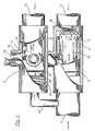
- Fig. 4 shows a further variant of a closable jet nozzle according to the invention through which compressed air is blasted into the inner basin.
- the nozzle housing 44 is preferably clamped to the surrounding wall of the water basin by a lock nut 38. At least one nozzle mouth 47 points towards the inner basin 14, a multi-jet design and / or a nozzle cover is conceivable.
- the nozzle housing preferably carries 2 connecting pieces 57, 58 which serve for the supply and discharge of compressed air and / or residual water.
- a valve body 10 is preferably arranged in a cylindrical shape and radial O-ring seal 12.
- the valve body opens the nozzle orifice 47 arranged radially to the valve body 10 in the direction of the inner basin 14 by movement in the direction from E to F. If compressed air is supplied to the connecting piece 57, the valve body closes the nozzle mouth 47 by moving in the direction from F to E and at the same time opens the radially arranged bypass 59. The compressed air leaves the nozzle housing through the connecting piece 58. A plurality of such nozzles are preferably connected in series. The compressed air supplied in the direction from F to E expels any type of residual water that has entered the supply system.
- valve body 10 it is also possible to move this valve body on the one hand through the transport medium, for example to open it and on the other hand to close it by means of a compression spring.
- a non-return valve 60 which closes by spring force in the space between valve body 10 and nozzle orifice 47.
- Such backflow safeguards are known as check valves.
- the opening is made by the flowing transport medium, the closure is made by spring force.
- the switching of the valve body 10 can be effected by reversing the transport medium flow direction as described above, but it is also possible to work with two different pressure generators, one pressure generator generating the compressed air for the formation of air bubbles and the second pressure generator producing the compressed air for closing the Valve body and generated to expel residual water.
- an independent unit such as a hydraulic or pneumatic device with its own control lines. Such devices are known from hydraulic and / or pneumatic control technology.
- the bypass 59 can be incorporated directly into the single-jet nozzle housing 44. However, it is also possible to create the bypass by additional connecting pieces and a connecting line. It is conceivable to connect all connections with simple hose lines accordingly.
- the end stop of the valve body 10 preferably takes place on the one hand through the cross-sectional constriction 61 towards the connecting piece 58 and on the other hand through the threaded connection 62 screwed in connection nipple 57 which serves as an end stop for the valve body 10 in position F on the inside of the nozzle housing.
- a check valve in the form of a backflow preventer, which blocks backflow in direction F, can preferably be inserted within the bypass line 59.
- the blower 63 generates compressed air for air bubbling operation, for switching the valve body 10 and for expelling residual water from the supply system.
- the nozzle housing 44 is clamped to the peripheral walls of the water basin 2.
- the compressed air passes via line 64, preferably with a backflow-preventing bend 46, to the multi-way valve 4 and via line 65 to the jet nozzles 7/44, which are connected to one another by line 66.
- the supply of compressed air via line 65 is interrupted and released via line 67 to the jet nozzles 7/44.
- valve bodies 10, 27, 43 are switched within the nozzle housings 7, 21, 44, the nozzle orifices are closed, the compressed air reaches the connecting line 66 via the bypass 59 from position F to position E, etc.
- the multi-way valve 4 blocks the line 65.
- the compressed air, together with the expelled residual water, reaches the collecting container 68 in which residual water separates from the compressed air.
- the residual water is drained off to the channel.
- a float valve is preferably used, which opens when water is generated and is closed in the idle state. Drain 70 serves towards the channel.
- the compressed air is from the top of the Collection container 68 derived, it serves as Air separators, such constructions for separation from various media are known.
- the Compressed air is removed from the collection container via line 71 dissipated, preferably serves the Drain the compressed air, a solenoid valve 45 accordingly switched with the multi-way valve 4 becomes.
- the compressed air can be released or be fed back to the blower 63.
- a Pipe loop 46 prevents the supply of water to the blower.
- a supply container 31 is preferably connected into line 67, from which one or more addition substances can be added during circulation mode of operation.
- the addition can take place by means of an injection effect or via a controlled valve which controls the discharge from the container 31 accordingly.
- compressed air it is also conceivable to apply compressed air to the storage container 31 and, for example, to introduce or spray the added substances into the line 67 by means of compressed air.
- a separate pressure generator preferably a pump 55, can be connected to the reservoir 31, through which flushing agent can be introduced into the circulation circuit.
- the pump 55 can, however, also serve to move the valve bodies 10, 27, 43.
- each air bubbling operation first followed by a liquid flushing phase and then a compressed air flushing phase, with residual water quantities of all kinds from the supply system in the last flushing phase driven out, which are drained together with the liquid detergent from the collecting container 68 to the channel.
- a pipe loop 46 is also preferably installed in line 71, which prevents water from flowing back to the blower.
- the line 71 also carries a ventilation 52 through which the fan sucks in fresh air.
- the blower with feed lines, collecting container and storage container 31 is preferably accommodated below the water basin 2 or within its casing. It is advantageous to place the filling opening 74 for the reservoir 31 in the area of the edge of the water basin so that the refill can be carried out from an easily accessible location.
- the main pump 1 with at least 2 power ranges and to use the low power range for the circulation, it is advantageous to choose a small pump for this, which independently takes over the circulation operation with less energy consumption and with far less noise.
- the circulation pump can also be used to evacuate residual water, it is easy to control and can be included in an automated program.
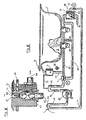
- a backflow preventer 60 is inserted into the housing 44 with inlet opening 47 and nozzle opening 13 towards the inner pool 14.
- the ball valve 43 is movably mounted between the seats in pos. And G.
- the housing carries two connecting pieces 57 and 58, which serve to supply a medium, preferably compressed air and / or circulation medium. Furthermore, the connection 58 and the connection 57 can be used to discharge residual water.
- a float ball preferably serves as valve body 43. When residual water enters the nozzle housing 44, the valve body 43 floats and allows the residual water to flow out of the nozzle housing in position F.
- the drain can be fed to the channel.
- a collecting container as described above, is also conceivable.
- circulation means is supplied to the nozzle housing 44 via the connection 57.
- the valve body 43 is guided from position F to position G and closes the entrance to the inner pool 14 there.
- the circulation medium reaches item E and is continued via the nozzle 58, preferably to one or more subsequent single-jet nozzle housings.
- the inlet to the inner pool can also be single or multi-jet.
- a distributor cover is also conceivable. All of the above-described devices according to the invention, which serve to transport a medium or a circulation medium, can be used in combination.
- the connecting pieces 57, 58 can be molded or attached directly to the nozzle housing, the valve body 43 of course also being able to be used from the inside of the water basin, for this purpose only the constriction in item G needs to be inserted as a screw part into the nozzle housing.
- the connecting pieces can of course also both be attached to the rear housing part, or be designed as side outlets.
- a connection to an existing pressure line, such as a water line or compressed air line, can also be used as an additional pressure generator.
- the pressure generator 55 can thus also be a corresponding connection to an existing pressure line.
Landscapes
- Health & Medical Sciences (AREA)
- Public Health (AREA)
- Epidemiology (AREA)
- Pain & Pain Management (AREA)
- Physical Education & Sports Medicine (AREA)
- Rehabilitation Therapy (AREA)
- Life Sciences & Earth Sciences (AREA)
- Animal Behavior & Ethology (AREA)
- General Health & Medical Sciences (AREA)
- Veterinary Medicine (AREA)
- Nozzles (AREA)
- Aeration Devices For Treatment Of Activated Polluted Sludge (AREA)
- Special Spraying Apparatus (AREA)
- Structures Of Non-Positive Displacement Pumps (AREA)
- Catching Or Destruction (AREA)
- Percussion Or Vibration Massage (AREA)
- Cleaning In General (AREA)
Claims (9)
- Bassin équipé d'un dispositif de génération de bulles d'air pourvu d'un système de conduites présentant une pompe de circulation (1), une conduite d'aspiration d'eau (15) et au moins un injecteur (7), pour l'injection de deux ou plusieurs milieux, l'injecteur étant connecté avec au moins deux conduites de milieux (eau 6,17, air 24,57,65), caractérisé par le fait que pour rincer à l'air l'exit de l'air d'injecteur (7) au bassin intérieur est fermable par un corps de soupape (27) d'injecteur et que le système de conduites est concu en tant que circuit de circulation et que des moyens (compresseur d'air) sont prevus, ce qui permet par un corps de soupape (10) d'injecteur d'acheminer de l'air comprimé au circuit de circulation, ce que permet de rincer le circuit de circulation à l'air et de rejeter l'eau résiduelle dans le canal par soufflage (purge) à l'air comprimé.
- Bassin suivant la revendication 1, caractérisé par le fait qu'un séparateur est prévu pour l'air en amont du raccordement au canal.
- Bassin suivant revendication 1 ou 2, caractérisé par le fait que le compresseur d'air utilisé pour la génération de bulles d'air est employé pour purger.
- Bassin suivant l'une des revendications 1 à 3, caractérisé par le fait q'à la phase d'exploitation système de bulles d'air (bains-bulles) fait suite une phase de rincage liquide, puis une phase de rincage à l'air comprimé qui, elle, permet de purger les conduites en èjectant l'eau résiduelle du système de conduites.
- Bassin suivant l'une des revendications 1 à 4, caractérisé par le fait que la conduite d'aération (28) est pourvue d'une soupape anti-retour (29) permettant d'empêcher la sortie du milieu de rincage ou de circulation (air).
- Bassin suivant l'une des revendications 1 à 5, caractérisé par le fait que les différents sytèmes de conduites pour l'eau et/ou pour l'air sont équipés chacun de leur propre conduite de circulation et de leur propre compresseur d'air (55) ce qui permet, indépendanment des différents modes d'exploitation possibles, de mettre le milieu de circulation (eau ou air) en circulation.
- Bassin suivant l'une des revendications 1 à 6, caractérisé par le fait que la pompe de circulation et le compresseur d'air (55) sont intégrés dans un programme permettant l'automation.
- Bassin suivant l'une des revendications 1 à 7, caractérisé par le fait que le carter des injecteurs (7,21,44) est pourvu d'au moins une connexion (18,58,57) concue en tant que sortie de purge de l'eau résiduelle.
- Bassin suivant l'une des révendications 1 à 8, caractérisé par le fait que l'air sous pression acheminé jusqu'au système de conduites peut être mélangé avec des additifes pour la désinfection.
Applications Claiming Priority (4)
| Application Number | Priority Date | Filing Date | Title |
|---|---|---|---|
| DE19873715010 DE3715010C2 (de) | 1987-05-06 | 1987-05-06 | Wasserbecken mit Luftsprudelvorrichtung |
| DE3715010 | 1987-05-06 | ||
| EP91108118A EP0454177B1 (fr) | 1987-05-06 | 1988-05-03 | Bassin d'eau à jet d'air avec valve de retenue dans la conduite d'aspiration |
| EP88107070A EP0297246B1 (fr) | 1987-05-06 | 1988-05-03 | Bassin d'eau à jet d'air avec injecteurs directionnels verrouillables et avec conduites de circulation |
Related Parent Applications (3)
| Application Number | Title | Priority Date | Filing Date |
|---|---|---|---|
| EP88107070.0 Division | 1988-05-03 | ||
| EP91108118A Division EP0454177B1 (fr) | 1987-05-06 | 1988-05-03 | Bassin d'eau à jet d'air avec valve de retenue dans la conduite d'aspiration |
| EP91108118.0 Division | 1988-05-03 |
Publications (3)
| Publication Number | Publication Date |
|---|---|
| EP0590228A1 EP0590228A1 (fr) | 1994-04-06 |
| EP0590228B1 EP0590228B1 (fr) | 1995-08-09 |
| EP0590228B2 true EP0590228B2 (fr) | 2002-01-02 |
Family
ID=6326907
Family Applications (3)
| Application Number | Title | Priority Date | Filing Date |
|---|---|---|---|
| EP93103458A Expired - Lifetime EP0590228B2 (fr) | 1987-05-06 | 1988-05-03 | Bassin d'eau avec dispositif à jets d'air |
| EP91108118A Revoked EP0454177B1 (fr) | 1987-05-06 | 1988-05-03 | Bassin d'eau à jet d'air avec valve de retenue dans la conduite d'aspiration |
| EP88107070A Expired - Lifetime EP0297246B1 (fr) | 1987-05-06 | 1988-05-03 | Bassin d'eau à jet d'air avec injecteurs directionnels verrouillables et avec conduites de circulation |
Family Applications After (2)
| Application Number | Title | Priority Date | Filing Date |
|---|---|---|---|
| EP91108118A Revoked EP0454177B1 (fr) | 1987-05-06 | 1988-05-03 | Bassin d'eau à jet d'air avec valve de retenue dans la conduite d'aspiration |
| EP88107070A Expired - Lifetime EP0297246B1 (fr) | 1987-05-06 | 1988-05-03 | Bassin d'eau à jet d'air avec injecteurs directionnels verrouillables et avec conduites de circulation |
Country Status (3)
| Country | Link |
|---|---|
| EP (3) | EP0590228B2 (fr) |
| AT (3) | ATE73642T1 (fr) |
| DE (5) | DE3745018C2 (fr) |
Families Citing this family (13)
| Publication number | Priority date | Publication date | Assignee | Title |
|---|---|---|---|---|
| IT8846837A0 (it) * | 1988-04-20 | 1988-04-20 | Ideal Standard Spa | Impianto di idromassaggio autopulente per vasche da bagno in genere |
| DE3902117C1 (fr) * | 1989-01-25 | 1990-09-13 | Guenter 6074 Roedermark De Schuessler | |
| DE4108539A1 (de) * | 1991-03-15 | 1992-09-17 | Hoesch Metall & Kunststoffwerk | Verfahren zur desinfektion von rohrleitungssystemen sanitaerer anlagen und whirlpool-anlagen zur durchfuehrung des verfahrens |
| DE4108719C2 (de) * | 1991-03-18 | 1999-08-12 | Guenter Schuessler | Sprudelbadewanne mit einem Umlaufsystem |
| EP0557233B1 (fr) * | 1992-02-18 | 1996-11-13 | Iberspa, S.A. | Buse pour baignoires d'hydromassage |
| ES2063624B1 (es) * | 1992-02-18 | 1997-04-16 | Iberspa Sa | Boquilla para bañeras de hidromasaje. |
| DE4395718C1 (de) * | 1992-11-09 | 1997-12-04 | Schuessler Guenter | Wasserbecken mit einem durch den Innenraum des Beckens führenden Kreislaufsystem |
| WO1994010964A1 (fr) * | 1992-11-09 | 1994-05-26 | Schuessler Guenter | Dispositif et procede pour le fonctionnement d'un dispositif a jet comportant un boitier a brides et associe a un bassin a eau |
| DE19524792A1 (de) * | 1995-07-07 | 1997-01-09 | Guenter Dipl Ing Wuschik | Whirlpool |
| IT1279448B1 (it) | 1995-09-29 | 1997-12-10 | Jacuzzi Europ | Bocchetta di aspirazione per vasche d'idromassaggio |
| IT1294446B1 (it) * | 1997-07-03 | 1999-03-24 | Ideal Standard Spa | Gruppo di chiusura e collegamento, per bocchette d'idromassaggio |
| ITRE20030091A1 (it) * | 2003-09-29 | 2005-03-30 | American Standard Italia S R L | Bocchetta per vasche da idromassaggio. |
| US11603677B1 (en) * | 2022-04-06 | 2023-03-14 | Dongguan Hongyu Plastic Co., Ltd. | Spa bathtub and operating unit for the spa bathtub |
Family Cites Families (12)
| Publication number | Priority date | Publication date | Assignee | Title |
|---|---|---|---|---|
| DE2709674A1 (de) * | 1976-11-19 | 1978-09-14 | Baumann Beltron Gmbh | Luftregler fuer sprudelbaeder |
| DE2940269C2 (de) * | 1979-10-04 | 1983-10-20 | Horst 6712 Bobenheim Haseloff | Verfahren zur Reinigung des Badewassers bei einer im öffentlichen Bereich einsetzbaren Warmsprudelbeckenanlage (Whirlpool) und hierzu geeignete Vorrichtung |
| DE3331684A1 (de) * | 1983-09-02 | 1985-03-21 | MAG Walter Frenkel, 7483 Inzigkofen | Luftsprudelbadematte mit permanentmagnetischem zweiwegeventil |
| GB8400995D0 (en) * | 1984-01-14 | 1984-02-15 | James Ind Ltd | Bath installations/tubs |
| DE8416982U1 (de) * | 1984-06-02 | 1986-04-30 | Eberhard Hoesch & Söhne Metall und Kunststoffwerk GmbH & Co, 5166 Kreuzau | Wirbeldüsenwanne mit Systemvorspülung |
| IT8422589U1 (it) * | 1984-07-17 | 1986-01-17 | Jacuzzi Europe S P A | Bocchetta perfezionata per idromassaggio. |
| DE3507027A1 (de) * | 1984-08-23 | 1986-03-06 | Metronic Electronic GmbH, 7210 Rottweil | Druckluftverteiler fuer eine sprudelmatte eines luftsprudelmassagegeraetes |
| DE8606463U1 (de) * | 1985-04-26 | 1986-10-30 | Schüssler, Günter, 6074 Rödermark | Wasserbecken mit Luftsprudelvorrichtung |
| IT1200742B (it) * | 1985-09-17 | 1989-01-27 | Teuco Guzzini Srl | Vasca da bagno con impianto per idromassagio perfezionato |
| DE8627706U1 (de) * | 1986-10-17 | 1987-09-03 | Ucosan B.V., Roden | Reinigungseinrichtung für das Rohrleitungssystem einer Whirlpool-Wanne sowie Austrittsventil für Whirlpool-Wanne |
| DE3640497A1 (de) * | 1986-11-27 | 1988-06-09 | Ucosan Bv | Austrittsduese fuer das austrittsventil einer whirlpool-wanne |
| CH684306A5 (de) * | 1991-09-19 | 1994-08-31 | Jakko Knechtle | Sprudelbadewanne. |
-
1987
- 1987-05-06 DE DE3745018A patent/DE3745018C2/de not_active Revoked
- 1987-05-06 DE DE3745024A patent/DE3745024C2/de not_active Revoked
-
1988
- 1988-05-03 DE DE88107070T patent/DE3869228D1/de not_active Expired - Lifetime
- 1988-05-03 EP EP93103458A patent/EP0590228B2/fr not_active Expired - Lifetime
- 1988-05-03 DE DE3851545T patent/DE3851545D1/de not_active Revoked
- 1988-05-03 AT AT88107070T patent/ATE73642T1/de not_active IP Right Cessation
- 1988-05-03 EP EP91108118A patent/EP0454177B1/fr not_active Revoked
- 1988-05-03 AT AT93103458T patent/ATE126048T1/de not_active IP Right Cessation
- 1988-05-03 EP EP88107070A patent/EP0297246B1/fr not_active Expired - Lifetime
- 1988-05-03 DE DE3854306T patent/DE3854306D1/de not_active Expired - Fee Related
- 1988-05-03 AT AT91108118T patent/ATE111338T1/de not_active IP Right Cessation
Also Published As
| Publication number | Publication date |
|---|---|
| DE3851545D1 (de) | 1994-10-20 |
| EP0297246B1 (fr) | 1992-03-18 |
| DE3745024C2 (de) | 1995-01-19 |
| ATE126048T1 (de) | 1995-08-15 |
| DE3745018C2 (de) | 1995-11-23 |
| ATE73642T1 (de) | 1992-04-15 |
| DE3854306D1 (de) | 1995-09-14 |
| EP0454177A1 (fr) | 1991-10-30 |
| DE3869228D1 (en) | 1992-04-23 |
| EP0590228B1 (fr) | 1995-08-09 |
| EP0590228A1 (fr) | 1994-04-06 |
| ATE111338T1 (de) | 1994-09-15 |
| EP0454177B1 (fr) | 1994-09-14 |
| EP0297246A1 (fr) | 1989-01-04 |
Similar Documents
| Publication | Publication Date | Title |
|---|---|---|
| DE3635329C2 (fr) | ||
| EP0590228B2 (fr) | Bassin d'eau avec dispositif à jets d'air | |
| DE4239137C2 (de) | Energie- und wassersparende Duschvorrichtung | |
| DE68912958T2 (de) | Sich selbst reinigendes Hydromassage-System für Badewannen. | |
| EP0320696B2 (fr) | Baignoire de bain à remous comprenant un système de prérinçage automatique | |
| DE69311091T2 (de) | Luftkontrollsystem für hydropneumatischen Behälter | |
| DE3447772A1 (de) | Verfahren und vorrichtung zum desinfizieren des umlaufsystems einer whirlpool-badewanne | |
| EP0164068B1 (fr) | Système, avec prérinçage, de bain tourbillonnant | |
| DE3715010C2 (de) | Wasserbecken mit Luftsprudelvorrichtung | |
| EP0354596A2 (fr) | Dispositif de modification d'une baignoire pour bains à bulles d'air | |
| DE2807689A1 (de) | Wasserklosettbecken mit hydraulischem verschluss | |
| EP2426282A1 (fr) | Dispositif de rinçage | |
| DE3824834C2 (fr) | ||
| DE3508713A1 (de) | Badewannenanlage | |
| DE3826001A1 (de) | Vorrichtung zum durchspuelen des rohrleitungssystems einer bodenwanne | |
| DE8817131U1 (de) | Wasserbecken mit einem stroemungssystem und einem halteventil in der saufleitung | |
| DE69429638T2 (de) | Verfahren und Anlage zur Reinigung und/oder Desinfektion eines Hydromassagesystems | |
| DE2163235A1 (de) | Vorrichtung zum Belüften und zum Verhindern des Heberns in einem Warmwasserversorgungssystem | |
| DE2727337A1 (de) | Vorrichtung zum reinigen und desinfizieren der milchwege von rohrmelkanlagen | |
| EP0586826A1 (fr) | Urinoir avec rinçage et additif | |
| DE3941006A1 (de) | Whirlpoolduese | |
| DE4395718C1 (de) | Wasserbecken mit einem durch den Innenraum des Beckens führenden Kreislaufsystem | |
| DE1201311C2 (de) | Dosiergeraet zum Zumischen fluessiger Spuel- oder Waschmittel in das Zuflusswasser von Spuel- oder Waschanlagen | |
| DE69415146T2 (de) | Wasserklosettvorrichtung | |
| EP0386420A2 (fr) | Bain tourbillonnant |
Legal Events
| Date | Code | Title | Description |
|---|---|---|---|
| PUAI | Public reference made under article 153(3) epc to a published international application that has entered the european phase |
Free format text: ORIGINAL CODE: 0009012 |
|
| AC | Divisional application: reference to earlier application |
Ref document number: 454177 Country of ref document: EP |
|
| AK | Designated contracting states |
Kind code of ref document: A1 Designated state(s): AT BE CH DE FR GB IT LI NL SE |
|
| 17P | Request for examination filed |
Effective date: 19940310 |
|
| 17Q | First examination report despatched |
Effective date: 19940923 |
|
| GRAA | (expected) grant |
Free format text: ORIGINAL CODE: 0009210 |
|
| AC | Divisional application: reference to earlier application |
Ref document number: 454177 Country of ref document: EP |
|
| AK | Designated contracting states |
Kind code of ref document: B1 Designated state(s): AT BE CH DE FR GB IT LI NL SE |
|
| PG25 | Lapsed in a contracting state [announced via postgrant information from national office to epo] |
Ref country code: NL Free format text: LAPSE BECAUSE OF FAILURE TO SUBMIT A TRANSLATION OF THE DESCRIPTION OR TO PAY THE FEE WITHIN THE PRESCRIBED TIME-LIMIT Effective date: 19950809 Ref country code: IT Free format text: LAPSE BECAUSE OF FAILURE TO SUBMIT A TRANSLATION OF THE DESCRIPTION OR TO PAY THE FEE WITHIN THE PRESCRIBED TIME-LIMIT;WARNING: LAPSES OF ITALIAN PATENTS WITH EFFECTIVE DATE BEFORE 2007 MAY HAVE OCCURRED AT ANY TIME BEFORE 2007. THE CORRECT EFFECTIVE DATE MAY BE DIFFERENT FROM THE ONE RECORDED. Effective date: 19950809 Ref country code: FR Free format text: LAPSE BECAUSE OF FAILURE TO SUBMIT A TRANSLATION OF THE DESCRIPTION OR TO PAY THE FEE WITHIN THE PRESCRIBED TIME-LIMIT Effective date: 19950809 |
|
| REF | Corresponds to: |
Ref document number: 126048 Country of ref document: AT Date of ref document: 19950815 Kind code of ref document: T |
|
| REF | Corresponds to: |
Ref document number: 3854306 Country of ref document: DE Date of ref document: 19950914 |
|
| PG25 | Lapsed in a contracting state [announced via postgrant information from national office to epo] |
Ref country code: SE Effective date: 19951109 |
|
| ET | Fr: translation filed | ||
| GBT | Gb: translation of ep patent filed (gb section 77(6)(a)/1977) |
Effective date: 19951120 |
|
| PLAV | Examination of admissibility of opposition |
Free format text: ORIGINAL CODE: EPIDOS OPEX |
|
| PLBQ | Unpublished change to opponent data |
Free format text: ORIGINAL CODE: EPIDOS OPPO |
|
| PLBI | Opposition filed |
Free format text: ORIGINAL CODE: 0009260 |
|
| PLBQ | Unpublished change to opponent data |
Free format text: ORIGINAL CODE: EPIDOS OPPO |
|
| PLBI | Opposition filed |
Free format text: ORIGINAL CODE: 0009260 |
|
| PLAV | Examination of admissibility of opposition |
Free format text: ORIGINAL CODE: EPIDOS OPEX |
|
| PLBF | Reply of patent proprietor to notice(s) of opposition |
Free format text: ORIGINAL CODE: EPIDOS OBSO |
|
| 26 | Opposition filed |
Opponent name: UCOSAN B.V. Effective date: 19960501 |
|
| 26 | Opposition filed |
Opponent name: EISENWERKE FRIED. WILH. DUEKER GMBH & CO. Effective date: 19960509 Opponent name: UCOSAN B.V. Effective date: 19960501 |
|
| NLR1 | Nl: opposition has been filed with the epo |
Opponent name: EISENWERKE FRIED. WILH. DUEKER GMBH & CO. Opponent name: UCOSAN B.V. |
|
| PLBF | Reply of patent proprietor to notice(s) of opposition |
Free format text: ORIGINAL CODE: EPIDOS OBSO |
|
| PGFP | Annual fee paid to national office [announced via postgrant information from national office to epo] |
Ref country code: GB Payment date: 19970428 Year of fee payment: 10 |
|
| RDAH | Patent revoked |
Free format text: ORIGINAL CODE: EPIDOS REVO |
|
| APAC | Appeal dossier modified |
Free format text: ORIGINAL CODE: EPIDOS NOAPO |
|
| APAE | Appeal reference modified |
Free format text: ORIGINAL CODE: EPIDOS REFNO |
|
| APAC | Appeal dossier modified |
Free format text: ORIGINAL CODE: EPIDOS NOAPO |
|
| PG25 | Lapsed in a contracting state [announced via postgrant information from national office to epo] |
Ref country code: GB Free format text: LAPSE BECAUSE OF NON-PAYMENT OF DUE FEES Effective date: 19980503 |
|
| GBPC | Gb: european patent ceased through non-payment of renewal fee |
Effective date: 19980503 |
|
| APAC | Appeal dossier modified |
Free format text: ORIGINAL CODE: EPIDOS NOAPO |
|
| PGFP | Annual fee paid to national office [announced via postgrant information from national office to epo] |
Ref country code: FR Payment date: 20010523 Year of fee payment: 14 |
|
| PGFP | Annual fee paid to national office [announced via postgrant information from national office to epo] |
Ref country code: NL Payment date: 20010528 Year of fee payment: 14 Ref country code: BE Payment date: 20010528 Year of fee payment: 14 Ref country code: AT Payment date: 20010528 Year of fee payment: 14 |
|
| PGFP | Annual fee paid to national office [announced via postgrant information from national office to epo] |
Ref country code: CH Payment date: 20010529 Year of fee payment: 14 |
|
| PLAW | Interlocutory decision in opposition |
Free format text: ORIGINAL CODE: EPIDOS IDOP |
|
| PUAH | Patent maintained in amended form |
Free format text: ORIGINAL CODE: 0009272 |
|
| 27A | Patent maintained in amended form |
Effective date: 20020102 |
|
| AK | Designated contracting states |
Kind code of ref document: B2 Designated state(s): AT BE CH DE FR GB IT LI NL SE |
|
| REG | Reference to a national code |
Ref country code: CH Ref legal event code: AEN Free format text: AUFRECHTERHALTUNG DES PATENTES IN GEAENDERTER FORM |
|
| NLR2 | Nl: decision of opposition | ||
| PG25 | Lapsed in a contracting state [announced via postgrant information from national office to epo] |
Ref country code: AT Free format text: LAPSE BECAUSE OF NON-PAYMENT OF DUE FEES Effective date: 20020503 |
|
| PG25 | Lapsed in a contracting state [announced via postgrant information from national office to epo] |
Ref country code: LI Free format text: LAPSE BECAUSE OF NON-PAYMENT OF DUE FEES Effective date: 20020531 Ref country code: CH Free format text: LAPSE BECAUSE OF NON-PAYMENT OF DUE FEES Effective date: 20020531 Ref country code: BE Free format text: LAPSE BECAUSE OF NON-PAYMENT OF DUE FEES Effective date: 20020531 |
|
| NLV1 | Nl: lapsed or annulled due to failure to fulfill the requirements of art. 29p and 29m of the patents act | ||
| EN | Fr: translation not filed | ||
| REG | Reference to a national code |
Ref country code: CH Ref legal event code: PL |
|
| NLV1 | Nl: lapsed or annulled due to failure to fulfill the requirements of art. 29p and 29m of the patents act | ||
| APAH | Appeal reference modified |
Free format text: ORIGINAL CODE: EPIDOSCREFNO |
|
| PGFP | Annual fee paid to national office [announced via postgrant information from national office to epo] |
Ref country code: DE Payment date: 20061117 Year of fee payment: 19 |
|
| PG25 | Lapsed in a contracting state [announced via postgrant information from national office to epo] |
Ref country code: DE Free format text: LAPSE BECAUSE OF NON-PAYMENT OF DUE FEES Effective date: 20071201 |